LG Aria-34e User manual

Aria-34e Installation
Digital Key Telephone System
4. INSTALLATION............................................................................................................................................4-1
ISSUE 3 31/1/99
4.1 INTRODUCTION 1.3 31/1/99......................4-1
4.2 SITE PLANNING 1.3 31/1/99......................4-1
4.3 INSTALLATION PLANNING 1.3 31/1/99......................4-2
4.4 UNPACKING THE KSU 1.3 31/1/99......................4-2
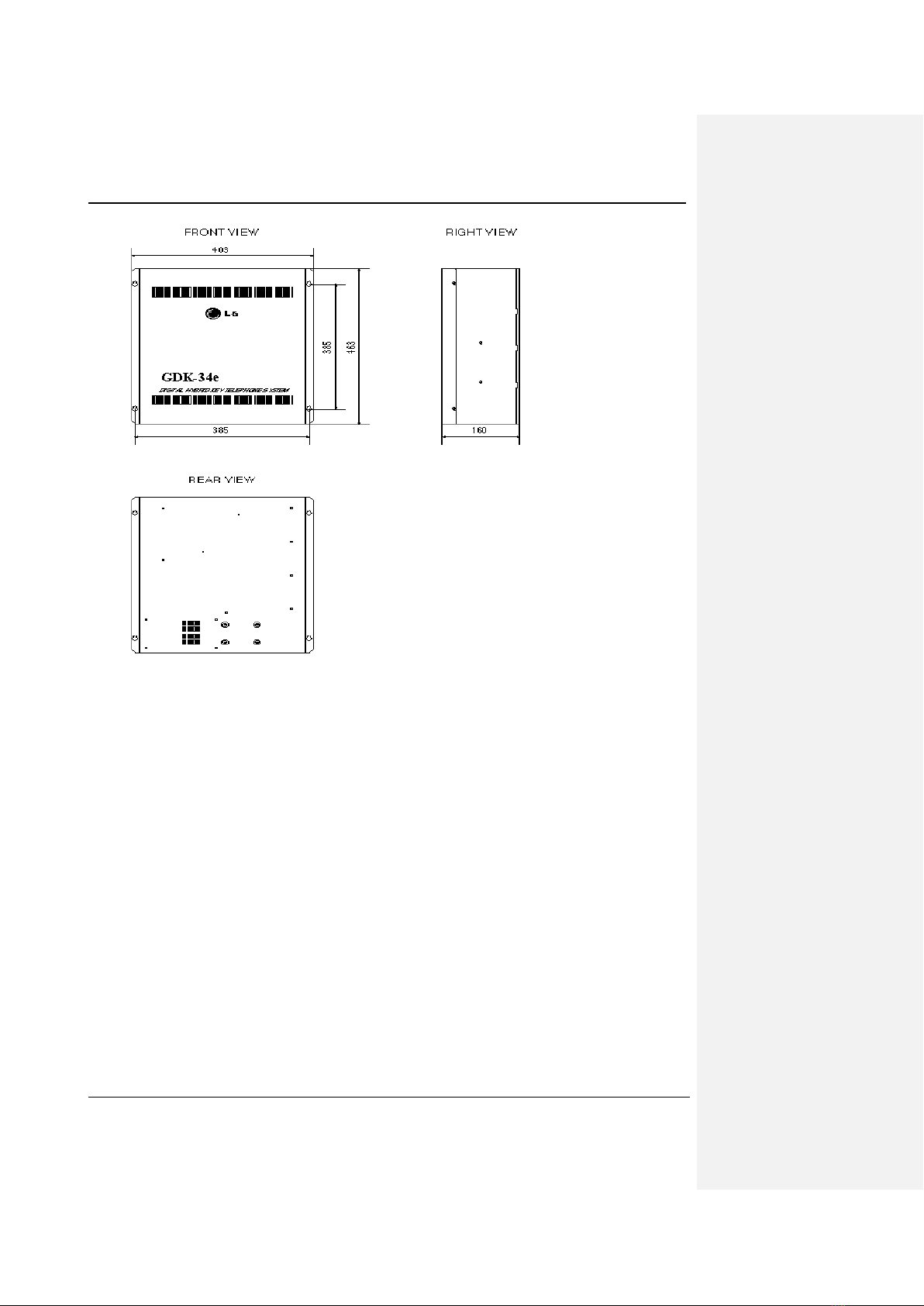
4.5 KSU EQUIPMENT MOUNTING 1.3 31/1/99......................4-3
4.5.1 KSU GROUNDING...........................................................................................................................4-6
4.5.2 POWER LINE SURGE PROTECTION...........................................................................................4-6
4.5.3 INSTALLING POWER SUPPLY UNIT ..........................................................................................4-6
4.5.4 POWER VOLTAGE SELECT..........................................................................................................4-7
4.5.5 BATTERY BACKUP INSTALLATION ...........................................................................................4-7
4.5.6 RING GENERATOR INSTALLATION...........................................................................................4-9
4.5.7 BOARD INSTALLATION ..............................................................................................................4-10
4.5.8 SOFTWARE ROM INSTALLATION ............................................................................................4-13
4.5.9 MAIN BOARD UNIT (MBU) INSTALLATION ...........................................................................4-13
4.5.10 MEMORY EXPANSION MODULE UNIT (MEMU) INSTALLATION......................................4-16
4.5.11 PHASE LOCK LOOP UNIT-2 (PLLU2) INSTALLATION..........................................................4-16
4.5.12 MODEM UNIT (MODU) INSTALLATION..................................................................................4-16
4.5.13 SERIAL INTERFACE UNIT (SIU) INSTALLATION .................................................................4-17
4.5.14 ANALOG CO/PABX LINE INTERFACE BOARDS (4LCO/LCOB) INSTALLATION..............4-18
4.5.15 ISDN 2BRI (2B+D: 2 BASIC RATE INTERFACE) INSTALLATION........................................4-20
4.5.16 ISDN PRI (30B+D: PRIMARY RATE INTERFACE) INSTALLATION.....................................4-20
4.5.17 ISDN STIB (S/T INTERFACE BOARD) INSTALLATION .........................................................4-21
4.5.18 ETIB (ELECTRONIC TERMINAL INTERFACE BOARD) INSTALLATION..........................4-22
4.5.19 DTIB (DIGITAL TERMINAL INTERFACE BOARD) INSTALLATION...................................4-23
4.5.20 SINGLE LINE TELEPHONE INTERFACE BOARD (4SLI, SLIB) INSTALLATION .............4-23
4.5.21 DIGITAL VOICE INTERFACE BOARD (DVIB) INSTALLATION...........................................4-24
4.5.22 PFTU (POWER FAILURE TRANSFER UNIT) INSTALLATION .............................................4-25
4.5.23 PFTU-I ............................................................................................................................................4-25
4.5.24 PFTU ...............................................................................................................................................4-26
4.6 SYSTEM WIRING 1.3 31/1/99....................4-28
4.6.1 BATTERY BACK-UP WIRING INSTALLATION........................................................................4-28
4.6.2 SIU RS-232C PORT WIRING........................................................................................................4-29
4.6.3 INSTALLATION TAILS - TERMINATION PROCEDURE ........................................................4-29
4.7 STATION WIRING 1.3 31/1/99....................4-30
4.7.1 Digital Keyset & Terminal Wiring..................................................................................................4-34
4.7.2 Electronic Keyset & Terminal Wiring ............................................................................................4-34
4.7.3 Single Line Telephone Wiring........................................................................................................4-35
4.7.4 Power Failure Transfer Wiring ......................................................................................................4-36
4.7.5 CO Line Wiring...............................................................................................................................4-38
4.7.6 Clock Control Cable Wiring............................................................................................................4-39
4.7.7 Music On Hold (MOH) Wiring.......................................................................................................4-42
4.7.8 External Paging Port (EXT. PAGE) Wiring ..................................................................................4-42
4.7.9 External Paging Port (EXT.PAGE) & General Purpose Relays Wiring.......................................4-42
4.7.10 Alarm Detect Port Wiring ...............................................................................................................4-43

Aria-34e Installation
Digital Key Telephone System
4.8 INSTALLATION CHECK LIST 1.3 31/1/99....................4-44

Aria-34e Installation
Digital Key Telephone System
Aria Communications Pty Ltd. Rev 1.3
A.C.N. 090 723 925
4-1
4. INSTALLATION
4.1 INTRODUCTION
As with any sophisticated communications device, installation of the Aria-34e System requires
the care and fore-thought of a competent technician. Installation proceeds in 4 major steps:
- Site Preparation
- KSU Installation
- PCB Installation
- System Wiring
4.2 SITE PLANNING
The Aria-34e key telephone system must not be subjected to harsh environmental conditions.
To ensure easy servicing and reliable operation, several factors must be considered when
planning the system installation. Always remember the following before installing the KSU and
wiring:
a) The BKSU and EKSU are designed for wall mounting or installation on a solid
backboard.
b) A 240V 10 Amp separately fused GPO is required. The GPO earth terminal must be
bonded to building Protective Earth (PE).
c) The KSU should be centrally located and care should be taken to stay within prescribed
cable lengths.
d) Thought should be given to the location of telephone conduits or cable runs.
e) A well-ventilated area having a temperature range of 0-50 degree C with a
recommended temperature range of 20-26 degree C and a humidity range of 10-95%
(non-condensing).
f) Lighting and accessibility to the KSU equipment for servicing.
g) Protection from flooding, flammable materials, excessive dust and vibration.
h) Avoid proximity of radio transmitting equipment, arc-welding devices, copy machines,
personal computers and other electrical equipment that are capable of generating
electrical interference.
Note: Some Computer terminals emit high levels if EMI! Beware!

Aria-34e Installation
Digital Key Telephone System
Aria Communications Pty Ltd. Rev 1.3
A.C.N. 090 723 925
4-2
4.3 INSTALLATION PLANNING
a) Aria-34e system has been designed as a plug-in card/unit type system to provide up to
38 port user capacity, with a maximum of 34 extension ports or CO Line ports.
b) Plug-in boards such as LCOB, 4LCO, ETIB, DTIB, SLIB, 4SLI, DVIB can be installed
in the system as required to expand system capacity.
c) New software packages with enhanced features will be commercially available as
advised by Aria Communications.
4.4 UNPACKING THE KSU
a) Remove the Key Service Unit from shipping carton and stand it upright on the level
working surface with the cover facing forward. Turn the 4 screws on the sides of the
cabinet and remove. Remove all packing materials from inside the KSU and inspect for
shipping damage. The KSU should be empty when received. Inside the KSU packing
should be a mounting template. The mounting template includes mounting dimensions
for the expansion cabinet.
b) The items listed below are needed to have an operating system. The number and type of
plug-in cards needed depends on the size of the system being installed.
KSU
Desired Interface Cards
1 x 27 Way Krone Frame With Lid
Installation Tails
Digital Keystation(s).

Aria-34e Installation
Digital Key Telephone System
Aria Communications Pty Ltd. Rev 1.3
A.C.N. 090 723 925
4-3
4.5 KSU EQUIPMENT MOUNTING
The KSU equipment is designed for wall mounting according to Figure 1.
Figure 1. Aria-34e KSU Mounting
The KSU must not be mounted directly on a masonry or dry walled surface. A wooden
backboard(plywood or pressed board) of sufficient size should be attached to the wall for the
KSU to be mounted upon. The KSU mounting template should be used to identify screw hole
locations. It is important that the KSU and MDF connecting blocks be mounted on the
backboard. See

Aria-34e Installation
Digital Key Telephone System
Aria Communications Pty Ltd. Rev 1.3
A.C.N. 090 723 925
4-4
Figure 2. for a typical system mounting dimensions. Insert 4 screws (#10 or larger) into the
backboard and tighten enough to hold the weight of the KSU. When the KSU is in position, the
screws should be tightened and the KSU should be securely mounted.

Aria-34e Installation
Digital Key Telephone System
Aria Communications Pty Ltd. Rev 1.3
A.C.N. 090 723 925
4-5
Figure 2. Aria-34e Dimensions

Aria-34e Installation
Digital Key Telephone System
Aria Communications Pty Ltd. Rev 1.3
A.C.N. 090 723 925
4-6
4.5.1 KSU GROUNDING
The Aria-34e Series of Digital Key Telephone Systems do not provide separate earth terminal
for PE (Protective Earth) and TRC (Telecom Reference Conductor). The Protective Earth
connection is via the 240VAC GPO and power cord. It is absolutely essential that the Protective
Earth terminal of the 240VAC GPO is bonded to the building protective earth system, as verified
by an electrician.
A separate TRC MUST NOT be installed.
The TRC is provided via a linking to the PE within the KSU equipment. The TRC/PE linking is
automatically engaged as each board is plugged into the KSU.
WARNING
ALL COMMUNICATION NETWORK CONNECTIONS MUST BE DISCONNECTED
FROM THE SYSTEM BEFORE THE AC POWER LEAD CAN BE REMOVED FROM
THE SYSTEM OR THE G.P.O
THE MAINS POWER LEAD MUST BE PLUGGED INTO THE G.P.O BEFORE
MAKING ANY CONNECTIONS TO THE NETWORK.
4.5.2 POWER LINE SURGE PROTECTION
It is recommended that the Aria-34e system should be equipped with a power-line transient
surge protection device at the 240VAC GPO. Systems equipped with such devices are more
resistant to damage from power line surges than unprotected systems. Power line surges often
occur during switching operations and especially during violent thunderstorm activity.
Installation of a surge protector meeting the specifications described here will prevent or
minimise the damage from power-line surges. The protector should be fast acting and capable of
protecting against transients greater than 400 volts.
4.5.3 INSTALLING POWER SUPPLY UNIT
The Power Supply Unit mounted within the system supplies power for the boards, key stations,
telephones and battery charging. The power unit will be installed during production.
The PSU circuitry is located on the right hand side in the base of the KSU. The recommended
operating conditions are:
Input Voltage
Fuse
220V ~ 240V
T1 A H 250V
Ensure the PSU is connected as in Figure 3.

Aria-34e Installation
Digital Key Telephone System
Aria Communications Pty Ltd. Rev 1.3
A.C.N. 090 723 925
4-7
Figure 3. PSU Connection
4.5.4 POWER VOLTAGE SELECT
The Power Supply Unit is set to 240VAC operation at the factory prior to shipping. There are no
other user adjustments.
4.5.5 BATTERY BACKUP INSTALLATION
The system can be backed-up by external batteries in case of 240VAC power failure. The
connector for the external battery is located on the base of the KSU. Connection from the Power
Unit to the external battery is via a GoldStar cable-assembly designed for this purpose.
a) A separate external 24 Volt DC battery or two separate 12 Volt DC batteries should be
provided.
b) Two 12 V DC batteries are serially connected to the BAT.+,- lead of AC/DC power
supply for the basic cabinet. See following Figure 4.
c) The battery is charged by the charging circuit in the AC/DC power supply during
normal system operation. During AC power loss, the battery will supply power for the
system without power interruption.
d) The chart below gives the approximate backup time for the Aria-34e series.

Aria-34e Installation
Digital Key Telephone System
Aria Communications Pty Ltd. Rev 1.3
A.C.N. 090 723 925
4-8
Battery
Capacity
Aria-34e
7 AH
10
26 AH
39
Figure 4. BATTERY BACK-UP CONNECTION

Aria-34e Installation
Digital Key Telephone System
Aria Communications Pty Ltd. Rev 1.3
A.C.N. 090 723 925
4-9
4.5.6 RING GENERATOR INSTALLATION
The Ring Generator Unit is needed in the Aria-34e KSU when any Single Line Telephone
Devices are supported. This includes a modem, fax or an industry standard AUSTEL approved
SLT. These devices interface with the 4SLI or SLIB cards in the system. The RGU is used to
provide ringing and message wait source power for the SLT devices.
The RGU is mounted on the bottom right side of the KSU with two (2) screws and is connected
to the Main Board Unit (MBU) on CN5 connector. A ferrite core (supplied) must be fitted to the
connecting cable from the RGU to the MBU for EMI suppression.
Figure 5. Ring Generator Unit Installation

Aria-34e Installation
Digital Key Telephone System
Aria Communications Pty Ltd. Rev 1.3
A.C.N. 090 723 925
4-10
4.5.7 BOARD INSTALLATION
WARNING: The power must be OFF when removing/installing all boards.
The printed circuit boards used to configure the system are referred to as PCB's.
The PCB's contain digital circuitry which, while extremely reliable, can be damaged by exposure
to excessive static. Please follow these precautions to when handling the boards minimise risk of
damage.
1. Keep all PCB's in their protective anti-static bags until they are installed in the KSU.
All PCB's that are not in protective bags should be handled by the card edges only.
2. Always use a ground wrist strip when handling PCB's. This will minimise the
possibility of static damage.
3. Never lay an unprotected PCB on a carpeted surface.
Note: The 3-Pin Plug must be plugged into the 240 VAC GPO to provide the system
earth.
The system provides Universal slots so that the CO line/Telephone ratio can be configured freely
up to the maximum configuration according to the user's requirement and system limitations.
To install a PCB, hold the card on the mounting knobs and, with the component side facing up,
insert the card into the system‟s card edge connector firmly and tighten the screw(s). To remove
a PCB, simply loosen the screw(s) and withdraw card.

Aria-34e Installation
Digital Key Telephone System
Aria Communications Pty Ltd. Rev 1.3
A.C.N. 090 723 925
4-11
Figure 6. PCB Installation
There are 7 slots in the Aria-34e system to extend or modify the system configuration.
However, there are some restrictions when installing the optional boards. The upper slot (slot #1)
is reserved for DVIB or STIB, the next slot (slot #2) is reserved only for 4SLI board, the next slot
(slot #3) is reserved for one of 4SLI, 2BRI, or PRI boards and the next four(4) slots(slot #4~7)
are universal slots.
Slot No.
Cards
Remark
SLOT 1
DVIB, STIB, WTIB
Option cards with own CPU
SLOT 2
4SLI
Fixed slot for 4SLI board
SLOT 3
4LCO,
Fixed slot for 4LCO or 2BRI/STIB
SLOT 4
SLOT 5
SLOT 6
SLOT 7
LCOB, STIB, SLIB,
DTIB, ETIB, DVIB, WTIB.
Universal Slot
*Not allowed for PRI, 2BRI, 4LCO,
4SLI

Aria-34e Installation
Digital Key Telephone System
Aria Communications Pty Ltd. Rev 1.3
A.C.N. 090 723 925
4-12
Figure 7. Slot Assignment
When the system is initialised, the default slot assignment is automatically defined according to
the board installation.

Aria-34e Installation
Digital Key Telephone System
Aria Communications Pty Ltd. Rev 1.3
A.C.N. 090 723 925
4-13
4.5.8 SOFTWARE ROM INSTALLATION
Software ROMS contain the integrated software to operate the system.
In the event of a software upgrade or change the ROM chips are inserted into their correct socket
by an authorised technician. Please refer to anti-static procedures in section 4.1.12 when
handling the boards and ROM chips.
Note: Correct tools and procedure for changing ROM chips must be followed.
4.5.9 MAIN BOARD UNIT (MBU) INSTALLATION
The MBU is installed during production. It comprises of the main processor, six(6) digital
terminal interface circuits, seven(7) card slots for optional boards, system memory, real-time
clock circuitry and data communication circuits which transmit and receives to/from peripheral
cards. The MBU may be equipped with four daughter boards; a MEMU for RAM expansion, a
MODU for remote access to the system, a PLLU2 for system synchronization when using digital
exchange line services and a SIU for serial data transmission. The MBU also provides ports and
contacts for the external paging, external Music On Hold , Alarm contacts and external control
contacts.
Refer to Figure 7 and Figure 8.
It should be noted that two SIU boards can be installed when the MODU is NOT installed. An
optional jumper pin which is contained in the SIU must be inserted between pin#1 and pin#2 of
MODU connector (CN21) in this case.
Background Music and Music On Hold Connection
Music On Hold, as well as background music, can be connected via a customer
provided radio, tape-deck etc. Connection for this feature is made via an AUSTEL
Approved MOH LIU (must be fitted as close as possible to the connecting device)
through the MOH port on the MBU.
General Purpose Relay Contacts
The Aria-34e provides two (2) dry relay contacts to activate optional external
equipment such as Loud Sounding Alarms on CO line ring etc. Connections for this
feature are made on the MDF and CHAMP cable assembly devices must be fitted.
AUSTEL Approved devices with ports assessed as TNV do not require an LIU. An
AUSTEL Approved LIU must be fitted to these ports when non-AUSTEL Approved
devices are specified, and this LIU must be connected as close as possible to the
connecting device.

Aria-34e Installation
Digital Key Telephone System
Aria Communications Pty Ltd. Rev 1.3
A.C.N. 090 723 925
4-14
External Paging Ports
One (1) external paging amplifier may be connected to the External Paging port on
the Aria-34e MBU. Connection for this feature is made via an AUSTEL Approved
MOH LIU (must be fitted as close as possible to the connecting device) through the
External Paging port on the MBU.
Alarm Switch Connection
There is an alarm function port on the MBU which provides for a normally open or
closed dry contact set as an input. Connections for this feature are made on the MDF
and CHAMP cable assemblies to the MDF must be fitted. AUSTEL Approved dry
contact devices assessed as TNV do not require an LIU. An AUSTEL Approved LIU
must be fitted to this port when non-AUSTEL Approved devices are specified, and
this LIU must be connected as close as possible to the connecting device.
Figure 8. MBU with MODU, SIU, MEMU and PLLU2
The MBU contains a lithium dry-cell to retain the contents of the programming database and
real-time clock functions during power off conditions. The battery is soldered to the MBU, and is
enabled by an on/off DIP switch (SW3). Please ensure the DIP switch is ON before the MBU
installation. Please refer to Figure 9.
Comment [N1]:

Aria-34e Installation
Digital Key Telephone System
Aria Communications Pty Ltd. Rev 1.3
A.C.N. 090 723 925
4-15
Figure 9. MEMORY BACK-UP SWITCH
The MBU also has a four position DIP switches (SW1). The following shows the function of
each switch position:
Switch 4 System data base initialize when power on
- on : Initialize system data base when power on
- off : Do not initialize system data base when power on
Switch 3 Trace control (software testing purposes)
- on : Race function off
- off : Trace function on
Switch 2 SMDI function control
- on : SMDI function off
- off : SMDI function on
Switch 1 Administration protection control
- on : Enable administration programming
- off : Disable administration programming
Before programming the system, switch 4 should be placed in the ON position and the system
power turned OFF and then ON to initialise the system database to default settings. This can also
be carried out through PGM 00. Once the database has been initialised, switch 4 should be
placed in the OFF position to protect the database programming in the memory in the event of a
power failure. Refer to Figure 9.
There are also four red LED‟s on the MBU. Their function is as follows:

Aria-34e Installation
Digital Key Telephone System
Aria Communications Pty Ltd. Rev 1.3
A.C.N. 090 723 925
4-16
LED4 Basic digital keyset in-use LED
- on : at least one port of six(6) digital terminal is busy (in-use state).
- off : all six(6) digital terminal ports are idle state.
LED3 Display task changing (software testing purpose)
- This LED will be turn on/off (toggle) when software tasks are changing.
LED2 Display event processing
- This LED will turn on during event processing
LED1 Display system software operation
- This LED will turn on and turn off at every 100 msec
4.5.10 S MEMORY EXPANSION MODULE UNIT (SMEMU) INSTALLATION
The SMEMU is a memory expansion module that locates on the MBU. The SMEMU contains a
Lithium dry cell battery to maintain memory in the event of a power outage or processor failure.
The battery is soldered to the SMEMU and connected to the circuitry by an on/off DIP switch.
Ensure that the DIP switch is moved to 'ON' before SMEMU installation.
The SMEMU expands the basic MPB RAM capacity to increase the following fields:
Increase SMDR record capacity from 100 to 2000
Increase ISDN CO message buffer from 0 to 1000
Increase ISDN DID conversion table form 0 to 10000 Program 05.
The SMEMU must be installed if the system is operating with Primary Rate ISDN installed.
Please refer to Figure 8.
4.5.11 PHASE LOCK LOOP UNIT-2 (PLLU2) INSTALLATION
The PLLU2 board must be installed on the MBU to synchronise with the network when the
ISDN boards are used (PRI, 2BRI, STIB). The PLLU2 locates on the MBU on connectors
dedicated for this purpose.
When the PRI, 2BRI or STIB cards are not installed, the PLLU2 is not used and a shorting
jumper strap must be installed across pin #12 and #13 of CN18 on the MBU. This causes the
system to generate internal clocking rather than synchronising from the ISDN network.
Please refer to Figure 8.
4.5.12 MODEM UNIT (MODU) INSTALLATION
The MODU is an internally mounted 2400baud modem used for remote access to the system for
system maintenance and PC-Admin programming functions. The MODU locates on the MBU
and is configured through programming. The MODU can be allocated to either a dedicated
station port or CO line port to enable dial in facilities.

Aria-34e Installation
Digital Key Telephone System
Aria Communications Pty Ltd. Rev 1.3
A.C.N. 090 723 925
4-17
When the MODU is allocated to a station port, the port does not require a station to be
connected.
If the MODU is installed the SIU(2) must be removed from the system.
Please refer to Figure 8.
4.5.13 SERIAL INTERFACE UNIT (SIU) INSTALLATION
The Serial Interface Unit is a plug in option card which locates on the MBU. The SIU provides
one (1) RS-232C port and provides an optional data path for a range of data streams generated by
the system. The SIU locates on the MBU by CN21. The system supports a total of two (2) SIU
cards when the MODU is not installed. The SIU is used for the functions of system maintenance,
PC-Admin, SMDR facilities and SMDI.
The following is a list of the system SIU outputs:
Admin database
Off-line SMDR (on demand)
On-line SMDR
SMDI
Statistical Information
System Trace data
It should be noted that two (2) SIU boards can be installed when the MODU in NOT installed.
In this case a shorting strap packed with the SIU must be inserted on pin #1 and #2 of MODU
connector CN21 on the MBU.
To install the SIU, plug edge connecting pins into locating sockets on MBU and push in. Ensure
screw on KSU frame is loose and then slide SIU mounting plate under screw and tighten.
Please refer to Figure 10 and Figure 11.

Aria-34e Installation
Digital Key Telephone System
Aria Communications Pty Ltd. Rev 1.3
A.C.N. 090 723 925
4-18
Figure 10. 1x SIU INSTALLATION
Figure 11. 2x SIU INSTALLATION
PROTOCOL = BAUD RATE, 8 DATA BITS, 0 STOP BITS, NO PARITY.
4.5.14 ANALOG CO/PABX LINE INTERFACE BOARDS (4LCO/LCOB)
INSTALLATION
There are several types of CO/PABX Line interface boards available. These boards include the
4LCO and LCOB (CO/PABX Line, Loop Start). Additional CO/PABX interface boards are
installed to meet customer specifications.
The major difference between these boards is shown in the table below. The 4LCO board can be
installed on slot #3 only and the LCOB can be installed on slot #4~7 (universal slots).
Both of these two boards provide four(4) Loop Start ports, can be optionally equipped with Call
Metering Unit (CMU50, CMU12k and CMUPR) to monitor call metering pulses and a Call
Progress Tone Unit (CPTU) to monitor call progress signals. The cards can also locate a DTMF
Table of contents
Other LG Telephone manuals