LGB 29272 User manual

Modell der Hg 3/3
29272

2

3
Inhaltsverzeichnis: Seite
Sicherheitshinweise 4
Wichtige Hinweise 4
Funktionen 4
Betriebshinweise 4
Multiprotokollbetrieb 4
Wartung und Instandhaltung 5
Schaltbare Funktionen 7
CV -Tabelle 8
Tabelle Funktionsmapping DCC 40
Bilder 42
Ersatzteile 44
Table of Contents: Page
Safety Notes 10
Important Notes 10
Functions 10
Information about operation 10
Multi-Protocol Operation 10
Service and maintenance 11
Controllable Functions 13
Table for CV 14
Table for Function Mapping DCC 40
Figures 42
Spare parts 44
Inhoudsopgave: Pagina
Veiligheidsvoorschriften 22
Belangrijke aanwijzing 22
Functies 22
Bedrijfsaanwijzingen 22
Multiprotocolbedrijf 22
Onderhoud en handhaving 23
Schakelbare functies 25
CV 26
Tabel functiemapping DCC 40
Afbeeldingen 42
Onderdelen 44
Indice del contenuto: Pagina
Avvertenze per la sicurezza 34
Avvertenze importanti 34
Funzioni 34
Avvertenze per ilfunzionamento 34
Esercizio multi-protocollo 34
Manutenzione ed assistere 35
Funzioni commutabili 37
CV 38
Tabella di mappatura delle Funzioni DCC 40
Figures 42
Pezzi di ricambio 44
Sommaire : Page
Remarques importantes sur la sécurité 16
Information importante 16
Fonctionnement 16
Remarques sur l’exploitation 16
Mode multiprotocole 16
Entretien et maintien 17
Fonctions commutables 19
CV 20
Tableau pour mapping des fonctions DCC 40
Images 42
Pièces de rechange 44
Indice de contenido: Página
Aviso de seguridad 28
Notas importantes 28
Funciones 28
Instrucciones de uso 28
Funcionamiento multiprotocolo 28
El mantenimiento 29
Funciones commutables 31
CV 32
Tabla de mapeado de funciones DCC 40
Figuras 42
Recambios 44

4
Sicherheitshinweise
• DasModelldarfnurmiteinemdafürbestimmten
Betriebssystem eingesetzt werden.
• NurSchaltnetzteileundTransformatorenverwenden,
die Ihrer örtlichen Netzspannung entsprechen.
• DasModelldarfnurauseinerLeistungsquelleversorgtwerden.
• BeachtenSieunbedingtdieSicherheitshinweiseinderBedienungsanleitungzu
Ihrem Betriebssystem.
• NichtfürKinderunter15Jahren.
• ACHTUNG!FunktionsbedingtescharfeKantenundSpitzen.
Wichtige Hinweise
• DieBedienungsanleitungistBestandteildesProduktesundmussdeshalbaufbe-
wahrt sowie bei Weitergabe des Produktes mitgegeben werden.
• GewährleistungundGarantiegemäßderbeiliegendenGarantieurkunde.
• FürReparaturenoderErsatzteilewendenSiesichbitteanIhrenLGB-Fachhändler.
• Entsorgung:www.maerklin.com/en/imprint.html
Funktionen
• DasModellistfürdenBetriebaufLGB-Zweileiter-Gleichstrom-Systemenmit
herkömmlichenLGB-Gleichstrom-Fahrpultenvorgesehen(DC,0-24V).
• WerkseitigeingebauterMultiprotokoll-Decoder(DC,DCC,mfx).
• Mfx-TechnologiefürMobileStation/CentralStation.
NameabWerk:DFB 5
• ZumEinsatzmitdemLGB-Mehrzugsystem(DCC)istdasModellaufLokadresse03
programmiert.ImBetriebmitmfxwirddieLokautomatischerkannt.
• VeränderbareLautstärkederGeräusche
• DieFunktionenkönnennurparallelaufgerufenwerden.DieseriealleFunktionsaus-
lösungistnichtmöglich(beachtenSiehierzudieAnleitungzuIhremSteuergerät).
Allgemeiner Hinweis zur Vermeidung elektromagnetischer Störungen:
UmdenbestimmungsgemäßenBetriebzugewährleisten,isteinpermanenter,
einwandfreierRad-Schiene-KontaktderFahrzeugeerforderlich.FührenSiekeine
VeränderungenanstromführendenTeilendurch.
Betriebsartenschalter
DasModellhateinenvierstugenBetriebsarten–SchalterimFührerstand(Bild1).
Pos.0 Lokstromlosabgestellt
Pos.1–3 Lokmotor,BeleuchtungundSoundeingeschaltet
Dampfentwickler
Das Modell ist mit einem Dampfentwickler ausgestattet. Den Schornstein nur zur
HälftemitderFlüssigkeitfüllen.WennzuvielFlüssigkeitverwendetwird,kanndiese
nicht verdampfen.
Elektronischer Sound
DiePfeifekannmitdembeiliegendenLGB-Sound-Schaltmagneten(17050)ausgelöst
werden.DerSchaltmagnetlässtsichzwischendieSchwellendermeistenLGB-
Gleiseklipsen.DerMagnetbendetsichseitlichversetztunterdemeingeprägten
LGB-Logo.
PlatzierenSiedenMagnetenaufeinerSeite,umdiePfeifekurzauszulösen,wenndie
LokdieseStelleüberquert.BeiAnordnungaufderanderenSeiteertöntdiePfeifelang.
Betrieb mit Zahnstange
• VermeidenSieSteigungenvonmehrals25%.
• VermeidenSiezuengeRadienaufZahnstangenabschnitten,dahierdasZahnrad
derLokseitlichvonderZahnstangerutschenkann.
• DamitdieFahrzeugenichtentkuppeln,empfehlenwir,alleWagenmitsymmetri-
schenKupplungen(KupplungshakenanbeidenEnden)auszurüsten.Vorneander
LokkannebenfallseinzweiterKupplungshakenmontiertwerden.
• FürdenZahnradbetriebempfehlenwir,dieKupplungshaken64462zuverwenden,
dasonstdieKupplungshakenaufderZahnstangeschleifenkönnen.
Multiprotokollbetrieb
Analogbetrieb
DerDecoderkannauchaufanalogenAnlagenoderGleisabschnittenbetriebenwer-
den.DerDecodererkenntdieanalogeGleichspannung(DC)automatischundpasst
sichderanalogenGleisspannungan.EssindalleFunktionen,dieuntermfxoderDCC
fürdenAnalogbetriebeingestelltwurdenaktiv(sieheDigitalbetrieb).
Die Eingebauten Sound-Funktionen sind ab Werk im Analogbetrieb nicht aktiv.
Digitalbetrieb
Der Decoder ist ein Multiprotokolldecoder. Der Decoder kann unter mfx oder DCC
eingesetzt werden.
Das Digital-Protokoll mit den meisten Möglichkeiten ist das höchstwertige Digital-
Protokoll.DieReihenfolgederDigital-ProtokolleistinderWertungfallend:
Priorität1:mfx;Priorität2:DCC;Priorität3:DC
Hinweis:Digital-Protokollekönnensichgegenseitigbeeinussen.Füreinenstö-
rungsfreienBetriebempfehlenwir,nichtbenötigteDigital-ProtokollemitCongura-
tionsVariable(CV)50zudeaktivieren.
DeaktivierenSie,soferndiesIhreZentraleunterstützt,auchdortdienichtbenötigten

5
Digital-Protokolle.
WerdenzweiodermehrereDigital-ProtokolleamGleiserkannt,übernimmtderDe-
coderautomatischdashöchstwertigeDigital-Protokoll,z.B.mfx/DCC,somitwirddas
mfx-Digital-ProtokollvomDecoderübernommen.
Hinweis:BeachtenSie,dassnichtalleFunktioneninallenDigital-Protokollenmöglich
sind.UntermfxundDCCkönneneinigeEinstellungenvonFunktionen,welcheim
Analog-Betriebwirksamseinsollen,vorgenommenwerden.
Hinweise zum Digitalbetrieb
• DiegenaueVorgehensweisezumEinstellenderdiversenCVsentnehmenSiebitte
derBedienungsanleitungIhrerMehrzug-Zentrale.
• DieabWerkeingestelltenWertesindfürmfxgewählt,sodasseinbestmöglichstes
Fahrverhaltengewährleistetist.FürandereBetriebssystememüssengegebenen-
fallsAnpassungengetätigtwerden.
mfx-Protokoll
Adressierung
• KeineAdresseerforderlich,jederDecodererhälteineeinmaligeundeindeutige
Kennung(UID).
• DerDecodermeldetsichaneinerCentralStationoderMobileStationmitseiner
UID-Kennungautomatischan.
Programmierung
• DieEigenschaftenkönnenüberdiegrascheOberächederCentralStationbzw.
teilweise auch mit der Mobile Station programmiert werden.
• Funktionsmapping:FunktionenkönnenmitHilfederCentralStation60212(einge-
schränkt)undmitderCentralStation60213/60214/60215beliebigenFunktionstasten
zugeordnetwerden(SieheHilfeinderCentralStation).
DCC-Protokoll
Adressierung
• KurzeAdresse–LangeAdresse–Traktionsadresse
• KurzeoderlangeAdressewirdüberdieCV29ausgewählt.
• EineangewandteTraktionsadressedeaktiviertdieStandard-Adresse.
Programmierung
• DieCVskönnenmehrfachgelesenundprogrammiertwerden(Programmierung
aufdemProgrammiergleis).
• DieCVskönnenbeliebigprogrammiertwerden(PoM-Programmierungaufdem
Hauptgleis).PoMistnichtmöglichbeidenCV1,17,18und29.PoMmussvonIhrer
Zentraleunterstütztwerden(sieheBedienungsanleitungihresGerätes).
• 14bzw.28/128Fahrstufeneinstellbar.
• AlleFunktionenkönnenentsprechenddemFunktionsmappinggeschaltetwerden.
• FürweitereInformationensieheCV-Tabelle
Wirempfehlen,dieProgrammierungengrundsätzlichaufdemProgrammiergleis
vorzunehmen.
WARTUNG
Schmierung
DieAchslagerunddieLagerdesGestängeshinundwiedermitjeeinemTropfen
Märklin-Öl(7149)ölen.
Austauschen des Dampfentwicklers
• Schornsteindrehenundnachobenabziehen(Abb.2).
• AbdeckungausdemSchornsteinziehen(Abb.3).
• BeschädigtenDampfentwickler(Schornsteineinsatz)miteinerSpitzzangeoder
einer Pinzette aus dem Schornstein ziehen.
• Kabeldurchtrennen(Abb.4).
• KabelmitdemneuenDampfentwicklerverbinden.DabeidieabisoliertenKabe-
lenden verdrehen und isolieren.
• NeuenDampfentwicklerindenSchornsteinschieben.
• Modellwiederzusammenbauen.
Austauschen der Glühlampen
Laternen (vorne unten):LampengehäusevomModellabziehen.Eingesteckte
GlühlampeausdemSockelziehen.NeueGlühlampeeinstecken.Modellwieder
zusammenbauen.
Laterne (vorne oben):LampengehäusenachvornevomModellabziehen.Einge-
steckteGlühlampeausdemSockelziehen.NeueGlühlampeeinstecken.Modell
wieder zusammenbauen.
Laternen (hinten):DieSchraubelösen,mitdenendieLaterneamLokgehäuse
befestigtist.Laterneabziehen.EingesteckteGlühlampeausdemSockelziehen.Neue
Glühlampeeinstecken.Modellwiederzusammenbauen.
Innenbeleuchtung:GlühlampemiteinerPinzetteausderFassungziehen.

6
Funktionsmapping DCC
Esistmöglich,dieFunktionalitäten,dievomDecodergesteuertwerden,denFunkti-
onstastennachWunschzuzuordnen(mappen).DazumussinderentsprechendenCV
ein entsprechender Wert eingetragen werden.
InderTabelleaufdenSeiten42/43sinddieCVs(Zeilen)unddieFunktionalitäten
(Spalten)aufgeführt.ZujederTastegehören4CVs.AusPlatzgründenwurdenabCV
282(TasteF5)die4CVszujederTastejeweilsineinerZeilezusammengefasst.
Grundsätzlichistesmöglich,einerTastemehrereFunktionalitäten,bzw.eineFunktio-
nalitätmehrerenTastenzuzuweisen.
Hinweis: Die Programmierung des Funktionsmappings sollte nur durch erfahrene
Anwenderdurchgeführtwerden.
JenachAuslegungdesDecoderskönneneinzelneFunktionalitätenüberSUSI
gesteuertsein.DieseFunktionalitätenwerdenvomDecoderalsSoundbehandelt.Die
zugehörigenLautstärkenkönnendannnichtverändertwerden.
Beispiele zum Funktionsmapping:
AUX2sollvorwärtsundrückwärtsaufFunktion3
CV 272 & CV 372 = 8
CV 273 & CV 373 = 0
CV 274 & CV 374 = 0
CV 275 & CV 375 = 0
Sound15sollvonvorwärtsundrückwärtsFunktion3aufFunktion8verlegtwerden.
DiebestehendeBelegungvonFunkton8wirddabeiüberschrieben.
CV 275 & CV 375 = 0
CV 273 & CV 373 = 0
CV 274 & CV 374 = 0
CV 275 & CV 375 = 0
CV 297 & CV 397 = 0
CV 298 & CV 398 = 0
CV 299 & CV 399 = 0
CV 300 & CV 400 = 4
Programmieren der CV mit dem Universal-Handy 55015
DerinIhrerLokomotiveeingebauteDecoderisteineWeiterentwicklungderbishe-
rigenLGB-Decoder-Technologie.DementsprechendstehenweitmehrFunktionali-
tätenzurVerfügungalsbisherüblich.
UmdieseFunktionalitätenandiepersönlichenBedürfnisseanpassenzukönnen,sind
gegenüberbisherigenDecodernjedochauchmehrEinstellmöglichkeitennotwendig.
Diese Einstellungen können auch mit dem Universal-Handy 55015 vorgenommen
werden.DadasUniversal-HandyjedochnochnichtfürdieseDecodervorgesehen
war,istdasrichtigeVorgehenhieretwasumständlicher.
Grundsätzlichistzwischen3verschiedenenProgrammiermethodenzuunterschei-
den:
• ProgrammierenüberRegister(bisCV5)
• ProgrammierenüberCV(bisCV255)
• ProgrammierenüberPages(bisCV1024)
DieeinzelnenProgrammierabläufesindimFolgendenbeschrieben.Voraussetzung
istjeweils,dassdasProgrammiermoduleingestecktistunddieLokomotivemitdem
DecoderaufdementsprechendenGleissteht.
Programmieren über Register
BeimProgrammierenüberRegisterkönnendieCV1–5programmiertwerden.
• wenndasProgrammiermoduleingestecktwird,zeigtdasHandy
--
.
• GebenSiediegewünschteCVzweistelligein,z.B.„02“.
• DasHandyzeigt
d -
• gebenSiejetztdengewünschtenWerteinundbestätigenSiemiteinemDruckauf
die Pfeiltaste .
• DasHandyzeigtwieder
--
.
DieProgrammierungistabgeschlossen,dergewünschteWertwurdeindenDecoder
programmiert.
Programmieren über CV
DieProgrammierungüberRegisterlässtnurVeränderungenandenCVs1–5zu.Um
höhereCVszuprogrammieren,isteineandereMethodenotwendig.DasProgrammie-
renüberCVerlaubtVeränderungenandenCVs1–255.
hin zu Funktion 8
weg von Funktion 3
vorwärts
rückwärts

7
Programmieren über Pages
MitderProgrammierungüberPageskönnenalleCVsbisCV1024verändertwerden.
DasVorgehenistgrundsätzlichmitdemProgrammierenüberCVvergleichbar,nutzt
allerdingsanStellederCV5fürdenWertdieCVs1bis4.Pagessind„Seiten“,auf
denen jeweils 4 Adressen zusammengefasst werden. Die CVs 1 bis 4 entsprechen
dannden4Adressen,dieaufderSeitezusammengefasstwurden.
DieeinzugebendenZahlenkönnenmitfolgendenGleichungenerrechnetwerden:
(CV-1)/4=Seite ganzzahligesErgebnisistdieSeite
(Nachkommax4)+1=DatenCV
Sollz.B.CV322sollauf200programmiertwerden,soergibtsichfolgendeRechnung:
(322-1)/4=80,25 Seite80; CV6=80
0,25x4+1=2 inCV2
UmdaszuProgrammieren,wirdzunächstinCV6die„Seite“80programmiertund
direkt im Anschluss in CV 2 der Wert 200.
Fahrstufen
Der Decoder kann wahlweise mit 14 oder 28/128 Fahrstufen betrieben werden
(CV29,Bit1).AchtenSiedarauf,dassdieEinstellungamDecoderzudenEinstellun-
genanIhremSteuergerätpassen.
Lange Adresse
DerDecoderkannunterDCCwahlweiseüberdiekurze(CV1,Adresse1–127)oder
dielangeAdresse(CV17&CV18,Adresse1–10239)gesteuertwerden.Grundsätz-
lichsindimmerbeideAdressenbelegt.MitCV29,Bit5wirdfestgelegt,welcheder
beiden Adressen aktuell gilt.
DieEinstellungenfürdielangeAdressewerdenwiefolgtberechnet:
X=Adresse/256(nurderganzzahligeAnteil)
CV17=X+192
CV18=Adresse–(Xx256)
Beispiel:
Adresse 1324
X=5(1324/256=5,17)
CV17=197(5+192=197)
CV18=44(5*256=1280;1324-1280=44)
Schaltbare Funktionen
BeleuchtungmitSchweizerLichtwechsel* LV+LR+
AUX2+
AUX 4
Geräusch:Pfeife 1 Sound 1
Geräusch:Bremsenquietschenaus 2 BS
Rauchgenerator 3 Aux 2
Geräusch:Bahnhofsansage 4 Sound 4
Geräusch:Kohleschaufeln 5 Sound 9
Geräusch:Betriebsgeräusch* 6 FS
BetriebsgeräuschmitZahnstange 7Sound
13+16
Sound an/aus 8 Sound 14
ABV,aus 9
Führerstandsbeleuchtung 10 AUX 3
Geräusch:Schaffnerpff 11 Sound 5
Rangierlicht doppel A 12 LV+LR+
AUX2+
AUX4
13
Geräusch:Pfeifekurz 14 Sound 2
Geräusch:Dampfablassen 15 Sound 15
* imAnalogbetriebaktiv
Hinweis:
Unterwww.LGB.dendenSieunter„ToolsundDownloads“eineausführliche
BeschreibungdesDecoderssowieeinTool,mitdemSieverschiedeneEinstellungen
berechnen können.

8
CV Belegung Bereich Default
1 Adresse 1 – 127 3
2 Minimalgeschwindigkeit 0 – 255 10
3 Anfahrverzögerung 0 – 255 15
4 Bremsverzögerung 0 – 255 15
5 Maximalgeschwindigkeit 0 – 255 255
8 Reset 8 131
13 Funktion F1 – F8 bei alternativem Gleissignal 0 – 255 32
14 Funktion FL, F9 – F15 bei alternativem Gleissignal 0 – 255 1
17 erweiterte Adresse, höherwertiges Byte 192 – 231 192
18 erweiterte Adresse, niederwertiges Byte 0 – 255 128
19 Traktionsadresse 0 – 255 0
21 Funktionen F1 – F8 bei Traktion 0 – 255 0
22 Funktionen FL, F9 – F15 bei Traktion 0 – 255 0
27 Bit 4: Bremsmodus Spannung gegen die Fahrtrichtung
Bit 5: Bremsmodus Spannung mit der Fahrtrichtung 0/16
0/32 16
29
Bit 0: Fahrtrichtung normal/invers
Bit 1: Anzahl der Fahrstufen 14/28(128)
Bit 2: Analogbetrieb aus/an
Bit 5: kurze / lange Adresse aktiv
0/1
0/2
0/4
0/32
6
50 Alternative Formate
Bit 1: Analog DC
Bit 3: mfx aus/an
0/2
0/8 10
53 Motorregelung - Regelreferenz 0 – 255 195
54 Motorregelung - Regelparameter K 0 – 255 15
55 Motorregelung - Regelparameter I 0 – 255 40
56 Motorregelung - Regeleinfluss 0 – 255 180
57 Dampfstoß 1 0 – 255 0
58 Dampfstoß 2 0 – 255 66
CV Belegung Bereich Default
60
Multibahnhofsansage
Bit 0 – 3: Anzahl der Bahnhöfe
Bit 4: Endansage wechselt die Reihenfolge
Bit 5: Lokrichtung wechselt die Reihenfolge
Bit 6: Vorgabe für Reihenfolge
0 – 15
0/16
0/32
0/64
38
63 Lautstärke gesamt 0 – 255 255
64 Schwelle für Bremsenquietschen 0 – 255 105
67 – 94 Geschwindigkeitstabelle Fahrstufen 1 – 28 0 – 255
112 Mapping Licht vorne, Modus 0 – 16 1
113 Mapping Licht vorne, Dimmer 0 – 255 255
114 Mapping Licht vorne, Periode 0 – 255 20
115 – 135 Mapping phys. Ausgänge, Licht hinten, Aux 1 – 6,
vgl. 112 – 114 0 – 16
0 – 255
137 Faktor Rangiergang 1 – 128 128
138 Lautstärke Bremsenquietschen 0 – 255 180
139 Lautstärke Betriebsgeräusch 0 – 255 180
140 Lautstärke Pfeife 0 – 255 180
141 Lautstärke Pfeife 0 – 255 180
143 Lautstärke Bahnhofsansage 0 – 255 180
144 Lautstärke Schaffnerpfiff 0 – 255 180
148 Lautstärke Kohle schaufeln 0 – 255 180
152 Lautstärke BetriebsgeräuschmitZahnstange 0 – 255 180
154 Lautstärke Dampf ablassen 0 – 255 180
155 Lautstärke BetriebsgeräuschmitZahnstange 0 – 255 180
176 Minimalgeschwindigkeit analog DC 0 – 255 110
177 Maximalgeschwindigkeit analog DC 0 – 255 255
257 – 260 Funktionsmapping Funktion FL vorwärts 0 – 255 257 = 41

9
CV Belegung Bereich Default
262 – 265 Funktionsmapping Funktion F1 vorwärts 0 – 255 263 = 16
267 – 270 Funktionsmapping Funktion F2 vorwärts 0 – 255 268 = 4
272 – 275 Funktionsmapping Funktion F3 vorwärts 0 – 255 272 = 4
277 – 280 Funktionsmapping Funktion F4 vorwärts 0 – 255 278 = 128
282 – 285 Funktionsmapping Funktion F5 vorwärts 0 – 255 284 = 16
287 – 290 Funktionsmapping Funktion F6 vorwärts 0 – 255 288 = 8
292 – 295 Funktionsmapping Funktion F7 vorwärts 0 – 255 295 = 9
297 – 300 Funktionsmapping Funktion F8 vorwärts 0 – 255 300 = 2
302 – 305 Funktionsmapping Funktion F9 vorwärts 0 – 255 303 = 1
307 – 310 Funktionsmapping Funktion F10 vorwärts 0 – 255 307 = 16
312 – 315 Funktionsmapping Funktion F11 vorwärts 0 – 255 314 = 1
317 – 320 Funktionsmapping Funktion F12 vorwärts 0 – 255 317 = 43
322 – 325 Funktionsmapping Funktion F13 vorwärts 0 – 255
327 – 330 Funktionsmapping Funktion F14 vorwärts 0 – 255 228 = 32
332 – 335 Funktionsmapping Funktion F15 vorwärts 0 – 255 335 = 4
337 – 340 Funktionsmapping Stand vorwärts 0 – 255
342 – 345 Funktionsmapping Fahrt vorwärts 0 – 255
347 – 350 Funktionsmapping Sensor 1 vorwärts 0 – 255
352 – 355 Funktionsmapping Sensor 2 vorwärts 0 – 255
357 – 360 Funktionsmapping Funktion FL rückwärts 0 – 255 357 = 42
362 – 365 Funktionsmapping Funktion F1 rückwärts 0 – 255 363 = 16
367 – 370 Funktionsmapping Funktion F2 rückwärts 0 – 255 368 = 4
372 – 375 Funktionsmapping Funktion F3 rückwärts 0 – 255 372 = 4
377 – 380 Funktionsmapping Funktion F4 rückwärts 0 – 255 378 = 128
382 – 385 Funktionsmapping Funktion F5 rückwärts 0 – 255 384 = 16
CV Belegung Bereich Default
387 – 390 Funktionsmapping Funktion F6 rückwärts 0 – 255 388 = 8
392 – 395 Funktionsmapping Funktion F7 rückwärts 0 – 255 395 = 9
397 – 400 Funktionsmapping Funktion F8 rückwärts 0 – 255 400 = 2
402 – 405 Funktionsmapping Funktion F9 rückwärts 0 – 255 403 = 1
407 – 410 Funktionsmapping Funktion F10 rückwärts 0 – 255 407 = 16
412 – 415 Funktionsmapping Funktion F11 rückwärts 0 – 255 414 = 1
417 – 420 Funktionsmapping Funktion F12 rückwärts 0 – 255 417 = 43
422 – 425 Funktionsmapping Funktion F13 rückwärts 0 – 255
427 – 430 Funktionsmapping Funktion F14 rückwärts 0 – 255 428 = 32
432 – 435 Funktionsmapping Funktion F15 rückwärts 0 – 255 435 = 4
437 – 440 Funktionsmapping Stand vorwärts rückwärts 0 – 255
442 – 445 Funktionsmapping Fahrt vorwärts rückwärts 0 – 255
447 - 450 Funktionsmapping Sensor 1 rückwärts 0 – 255
452 – 455 Funktionsmapping Sensor 2 rückwärts 0 – 255

10
Safety Notes
• Thismodelmayonlybeusedwiththeoperatingsystemdesignedforit.
• Useonlyswitchedmodepowersupplyunitsandtransformersthataredesigned
for your local power system.
• Thislocomotivemustneverbesuppliedwithpowerfrommorethanonepowerpack.
• Paycloseattentiontothesafetynotesintheinstructionsforyouroperatingsystem.
• Notforchildrenundertheageof15.
• WARNING! Sharp edges and points required for operation.
Important Notes
• Theoperatinginstructionsareacomponentpartoftheproductandmusttherefore
bekeptinasafeplaceaswellasincludedwiththeproduct,ifthelatterisgivento
someone else.
• Thewarrantycardincludedwiththisproductspeciesthewarrantyconditions.
• PleaseseeyourauthorizedLGBdealerforrepairsorspareparts.
• Disposing:www.maerklin.com/en/imprint.html
Functions
• ThismodelisdesignedforoperationonLGBtwo-railDCsystemswithconventio-
nalLGBDCtraincontrollersorpowerpacks(DC,0-24volts).
• Factory-installedmultipleprotocoldecoder(DC,DCC,mfx).
• MfxtechnologyfortheMobileStation/CentralStation.
Namesetatthefactory:DFB 5
•
Themodelisprogrammedwithlocomotiveaddress03forusewiththeLGBMulti
TrainSystem(DCC).Thelocomotiveisautomaticallyrecognizedinoperationwithmfx.
• Volumecanbechangedforthesoundeffects
• Thefunctionscanbeactivatedonlyinparallel.Serialactivationofthefunctionsis
notpossible(Pleasenoteheretheinstructionsforyourcontroller).
General Note to Avoid Electromagnetic Interference:
Apermanent,awlesswheel-railcontactisrequiredinordertoguaranteeoperation
for which a model is designed. Do not make any changes to current-conducting parts.
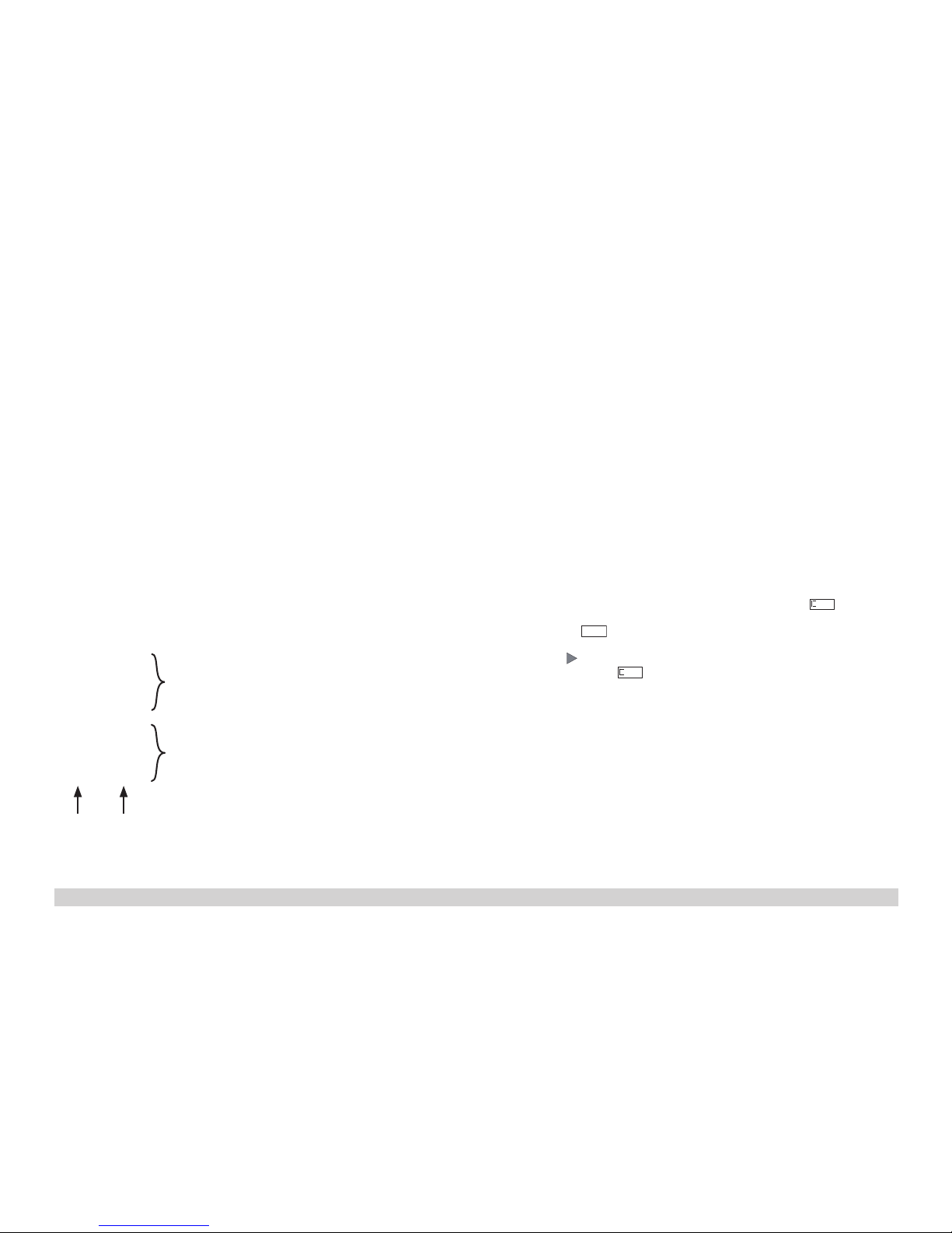
Mode of Operation Switch
This model has a four-position switch for the mode of operation. It is located in the
engineer‘scab(Figure1).
Pos.0 Locomotivestoredonasidingwithoutcurrent
Pos.1–3 Locomotivemotor,lighting,andsoundturnedon
Smoke Unit
This model is equipped with a smoke unit. Fill the smoke stack only halfway with
smokeuid.Ifyouputintoomuchuid,thesmokeunitcannotproducesmoke.
Sound
ThewhistlecanbeactivatedwiththeLGBsoundactivationmagnet(itemno.17050)
that is included with the locomotive. The activation magnet can be clipped into place
betweenthetiesofmostLGBtracksections.Placethemagnetontherightsideinor-
der to activate the short whistle blast when the locomotive passes over this location.
The long whistle blast will sound when the magnet is placed on the left side.
Operation with Rack
• Avoidgradesgreaterthan25%.
• Avoidsharpcurvesonracksections,sinceherethecogwheelonthelocomotive
can slip from the rack.
• Werecommendequippingallcarswithsymmetricalcouplers(couplerhooksat
bothends)sothatlocomotivesandcarsdonotuncouple.
• Werecommendthe64462couplerhooksforrackoperation,sinceotherwisethe
coupler hooks can drag on the rack.
Multi-Protocol Operation
Analog Operation
This decoder can also be operated on analog layouts or areas of track that are
analog.Thedecoderrecognizesalternatingcurrent(DC)andautomaticallyadapts
to the analog track voltage. All functions that were set under mfx or DCC for analog
operationareactive(seeDigitalOperation).
The built-in sound functions come from the factory inactive for analog operation.
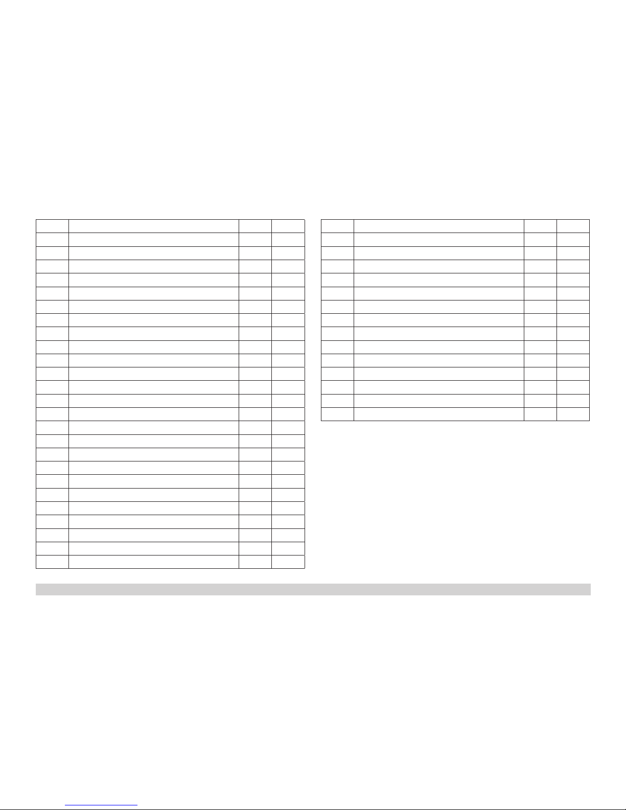
Digital Operation
This decoder is a multiprotocol decoder. This decoder can be used on mfx or DCC.
The digital protocol with the most possibilities is the highest order digital protocol.
Thesequenceofdigitalprotocolsindescendingorderis:
Priority1:mfx;Priority2:DCC;Priority3:DC
Note:Digitalprotocolscaninuenceeachother.Fortrouble-freeoperation,were-
commend deactivating those digital protocols not needed by using CV 50. Deactivate
unneeded digital protocols at this CV if your controller supports this function.
Iftwoormoredigitalprotocolsarerecognizedinthetrack,thedecoderautomatically
takesonthehighestorderdigitalprotocol,example:mfx/DCC;thedecodertakeson
themfxdigitalprotocol(seeprevioustable).
Note: Please note that not all functions are possible in all digital protocols. Several
settingsforfunctions,whicharesupposedtobeactiveinanalogoperation,canbe

11
done under mfx and DCC.
Notes on digital operation
• Theoperatinginstructionsforyourcentralunitwillgiveyouexactproceduresfor
setting the different parameters.
• Thevaluessetatthefactoryhavebeenselectedformfxinordertoguaranteethe
best possible running characteristics. Adjustments may have to be made for other
operating systems.
mfx Protocol
Addresses
•Noaddressisrequired;eachdecoderisgivenaone-time,uniqueidentier(UID).
• ThedecoderautomaticallyregistersitselfonaCentralStationoraMobileStation
with its UID-identifier.
Programming
• ThecharacteristicscanbeprogrammedusingthegraphicscreenontheCentral
Station or also partially with the Mobile Station.
• Functionmapping:Functionscanbeassignedtoanyofthefunctionbut-
tonswiththehelpofthe60212CentralStation(withlimitations)andwiththe
60213/60214/60215CentralStation(SeehelpsectionintheCentralStation).
DCC Protocol
Addresses
• Shortaddress–longaddress–multipleunitaddress
• ShortorlongaddressisselectedbymeansofCV29(Bit5).
•Amultipleunitaddressthatisbeinguseddeactivatesthestandardaddress.
Programming
• TheCVscanbereadandprogrammedrepeatedly.(Programmingisdoneonthe
programmingtrack.)
• TheCVscanbeprogrammedinanyorderdesired.(PoM-Programmingcanbe
doneonthemaintrack).PoMisnotpossiblewithCVsCV1,17,18,and29.PoM
mustbesupportedbyyourcentralcontroller(Pleaseseethedescriptionforthis
unit.).
• 14or28/126speedlevelscanbeset.
• Allofthefunctionscanbecontrolledaccordingtothefunctionmapping(seeCV
description).
• SeetheCVtableforadditionalinformation.
We recommend doing programming always on the programming track.
SERVICE
Lubrication
The axle bearings and the side rod bearings should be lubricated occasionally with a
smallamountofMärklin-Oil(7149).
Replacing the Smoke Unit
• Turnthesmokestackandpullup(Fig.2).
• Pullthecoveroffthesmokestack(Fig.3).
• Pullthedamagedsmokeunit(smokestackinsert)outofthesmokestackwitha
pair of tweezers.
• Separatethewires(Fig.4).
• Connectthewireswiththenewsmokeunit.Whendoingthis,twisttheendsofthe
wires and insulate the connections.
• Pushthenewsmokeunitintothesmokestack.
• Putthemodelbacktogether.
Replacing the Light Bulbs
Lanterns (front below): Remove the lamp housing from the model. Pull the light bulb
out of its socket. Plug the new light bulb into place. Put the model back together.
Lanterns (front above): Remove the lamp housing by pulling up from the model. Pull
the light bulb out of its socket. Plug the new light bulb into place. Put the model back
together.
Lanterns (rear):Loosenthescrewholdingthelanterninplaceonthelocomotive
body. Remove the lamp housing. Pull the light bulb out of its socket. Plug the new light
bulb into place. Put the model back together.
Interior Lighting: Pull the light bulb out of its socket with a pair of tweezers.

12
Function Mapping DCC
It is possible to assign functions controlled from the decoder to function buttons
ofyourchoice(mapping).Todothisanappropriatevaluemustbeenteredinthe
appropriate CV.
TheCVs(lines)andthefunctions(columns)arelistedinthetablesonpages42/43.
Four CVs belong to each button. For space reasons the 4 CVs were put together in
onelinestartingwithCV282(ButtonF5).
It is basically possible to assign several functions to one button or one function to
several buttons.
Note: The programming for function mapping should be done only by experienced
users.
Individual functions can be controlled by means of SUSI depending on the design of
the decoder. These functions can be handled by the decoder as sound. The volume
levels belonging to these functions cannot be changed.
Examples of Function Mapping:
AUX 2 is to be forwards and backwards on Function 3
CV 272 & CV 372 = 8
CV 273 & CV 373 = 0
CV 274 & CV 374 = 0
CV 275 & CV 375 = 0
Sound 15 is to be shifted from forwards and backwards on Function 3 to Function 8.
The existing function at Function 8 is overwritten in the process.
CV 275 & CV 375 = 0
CV 273 & CV 373 = 0
CV 274 & CV 374 = 0
CV 275 & CV 375 = 0
CV 297 & CV 397 = 0
CV 298 & CV 398 = 0
CV 299 & CV 399 = 0
CV 300 & CV 400 = 4
Programming the CV with the 55015 Universal Hand Controller
ThedecoderbuiltintoyourlocomotiveisafurtherdevelopmentofthepreviousLGB
decoder-technology. A lot more functions are available on this decoder than was
previously customary. More possibilities for making settings on the decoder are how-
ever,necessarycomparedtopreviousdecodersinordertobeabletoadaptthese
functions to your personal needs. These settings can also be done with the 55015 Uni-
versal Hand Controller. Since the Universal Hand Controller was not designed for this
decoder,thecorrectprocedurewiththiscontrollerissomewhatmoreinvolved.
Webasicallyhavetodifferentiateamong3differentprogrammingmethods:
• Programmingbymeansofregisters(uptoCV5)
• ProgrammingbymeansofCVs(uptoCV255)
• Programmingbymeansofpages(uptoCV1024)
The individual programming processes are described below. There is a requirement
in each case that the programming module is plugged in and the locomotive with the
decoder is standing on the corresponding track.
Programming by means of Registers (Universal-Handy 55015)
CV 1 – 5 can be programmed when programming by means of registers.
• Whentheprogrammingmoduleispluggedin,thehandcontrollerwill
show
--
.
• EnterthedesiredCVasatwo-digitnumber,example:„02“.
• Thehandcontrollerwillshow
d -
• Now,enterthedesiredvalueandconrmitbypressingonthearrow
button .
• Thehandcontrollerwillagainshow
--
.
The programming is complete and the desired value has been programmed into the
decoder.
Programming by means of CVs
Programming by means of CVs only allows changes to CVs 1 – 5. Another method
is necessary in order to program higher CVs. Programming by means of CVs allows
changes to CVs 1 – 255.
to Function 8
away from Function 3
forwards
backwards

13
Programming by means of Pages (Universal-Handy 55015)
All CVs up to CV 1024 can be changed with programming by means of pages. The
processcanbecomparedtoprogrammingbymeansofCVs,butitusestheCVs1to4
in place of CV 5 for the value. Pages are areas in which 4 addresses can be summa-
rized. CVs 1 to 4 correspond then to the 4 addresses that are summarized on the page.
Thenumberstobeenteredcanbegeneratedwiththefollowingequations:
(CV-1)/4=Page WholenumberresultisPage
(decimalx4)+1=DataCV
IfforexampleCV322istobeprogrammedat200,thefollowingcalculationwillresult:
(322-1)/4=80,25 Page80; CV6=80
0,25x4+1=2 ValueinCV2
Inordertoprogramthatthe„page“80isrstprogrammedinCV6andthevalue200
is immediately programmed in CV 2.
Speed Levels
Thisdecodercanbeoperatedwith14or28/128speedlevels(CV29,Bit1).Makesure
that the setting on the decoder is compatible with the settings on your controller.
Long Address
ThisdecodercanbecontrolledinDCCbymeansofashort(CV1,address1–127)
oralongaddress(CV17&CV18,address1–10239).Bothaddressesarebasically
alwaysoccupied.CV29,Bit5isusedtodeterminewhichofthetwoaddressesis
currently valid.
Thesettingsforthelongaddressarecalculatedasfollows:
X=Address/256(onlythewholenumberpart)
CV17=X+192
CV18=Address–(Xx256)
Example:
Address 1324
X=5(1324/256=5,17)
CV17=197(5+192=197)
CV18=44(5*256=1280;1324-1280=44)
Controllable Functions
Lighting* LV+LR+
AUX2+
AUX 4
LightingincludesSwisslightchangeover* 1 Sound 1
Soundeffect:Squealingbrakesoff 2 BS
Smoke generator 3 Aux 2
Soundeffect:Stationannouncements 4 Sound 4
Soundeffect:Coalbeingshoveled 5 Sound 9
Soundeffect:Operatingsounds* 6 FS
Operating sounds with rack 7 Sound
13+16
Sound on/off 8 Sound 14
ABV,off 9
Engineer‘s cab lighting 10 AUX 3
Soundeffect:Conductorwhistle 11 Sound 5
Double A switching light 12 LV+LR+
AUX2+
AUX4
13
Soundeffect:Shortwhistleblast 14 Sound 2
Soundeffect:Blowingoffsteam 15 Sound 15
* activeinanalogoperation
Note:
Atwww.LGB.de,youwillndat„ToolsandDownloads“anextensivedescriptionof
the decoder as well as a tool that you can use to calculate different settings.

14
CV Assignment Range Default
1 Address 1 – 127 3
2 Minimum speed 0 – 255 10
3 Acceleration delay 0 – 255 15
4 Braking delay 0 – 255 15
5 Maximum speed 0 – 255 255
8 Reset 8 131
13 Function F1 – F8 with alternative track signal 0 – 255 32
14 Function FL, F9 – F15 with alternative track signal 0 – 255 1
17 Expanded address, higher value byte 192 – 231 192
18 Expanded address, lower value byte 0 – 255 128
19 Multiple unit operation address 0 – 255 0
21 Functions F1 – F8 with multiple unit operation 0 – 255 0
22 Function FL, F9 – F15 with multiple unit operation 0 – 255 0
27
Bit 4: Braking mode voltage against the direction of travel
Bit 5: Braking mode voltage with the direction of travel
0/16
0/32 16
29
Bit 0: Direction normal/inverted
Bit 1: Number of speed levels 14/28(128)
Bit 2: Analog operation off/on
Bit 5: short / long address active
0/1
0/2
0/4
0/32
6
50
Alternative Formats
Bit 1: Analog DC
Bit 3: mfx off/on
0/2
0/8 10
53 Motor control – control reference 0 – 255 195
54 Motor control – control parameter K 0 – 255 15
55 Motor control – control parameter I 0 – 255 40
56 Motor control – control influence 0 – 255 180
57 steam chuff 1 0 – 255 0
58 steam chuff 2 0 – 255 66
CV Assignment Range Default
60
Multi-station announcement
Bit 0 – 3: Number of stations
Bit 4: Last announcement changes the sequence
Bit 5: Locomotive direction changes the sequence
Bit 6: Start for the sequence
0 – 15
0/16
0/32
0/64
38
63 Total volume 0 – 255 255
64 Threshhold for squealing brakes 0 – 255 105
67 – 94 Speed table for speed levels 1 – 28 0 – 255
112 Mapping lights in the front, mode 0 – 16 1
113 Mapping lights in the front, dimmer 0 – 255 255
114 Mapping lights in the front, cycle 0 – 255 20
115 – 135 Mapping phys. outputs, lights in the rear, Aux 1 – 6,
compare 112 – 114 0 – 16
0 – 255
137 Factor for switching range 1 – 128 128
138 Volume for squealing brakes 0 – 255 180
139 Volume for Operating sounds 0 – 255 180
140 Volume for whistle blast 0 – 255 180
141 Volume for whistle blast 0 – 255 180
143 Volume for Station announcements 0 – 255 180
144 Volume for Conductor whistle 0 – 255 180
148 Volume for Coal being shoveled 0 – 255 180
152 Volume for Operating sounds with rack 0 – 255 180
154 Volume for Blowing off steam 0 – 255 180
155 Volume for Operating sounds with rack 0 – 255 180
176 Minimum speed in analog DC 0 – 255 110
177 Maximum speed in analog DC 0 – 255 255
257 – 260 Function mapping Function FL forwards 0 – 255 257 = 41

15
CV Assignment Range Default
262 – 265 Function mapping Function F1 forwards 0 – 255 263 = 16
267 – 270 Function mapping Function F2 forwards 0 – 255 268 = 4
272 – 275 Function mapping Function F3 forwards 0 – 255 272 = 4
277 – 280 Function mapping Function F4 forwards 0 – 255 278 = 128
282 – 285 Function mapping Function F5 forwards 0 – 255 284 = 16
287 – 290 Function mapping Function F6 forwards 0 – 255 288 = 8
292 – 295 Function mapping Function F7 forwards 0 – 255 295 = 9
297 – 300 Function mapping Function F8 forwards 0 – 255 300 = 2
302 – 305 Function mapping Function F9 forwards 0 – 255 303 = 1
307 – 310 Function mapping Function F10 forwards 0 – 255 307 = 16
312 – 315 Function mapping Function F11 forwards 0 – 255 314 = 1
317 – 320 Function mapping Function F12 forwards 0 – 255 317 = 43
322 – 325 Function mapping Function F13 forwards 0 – 255
327 – 330 Function mapping Function F14 forwards 0 – 255 228 = 32
332 – 335 Function mapping Function F15 forwards 0 – 255 335 = 4
337 – 340 Function mapping standstill forwards 0 – 255
342 – 345 Function mapping running forwards 0 – 255
347 – 350 Function mapping Sensor 1 forwards 0 – 255
352 – 355 Function mapping Sensor 2 forwards 0 – 255
357 – 360 Function mapping Function FL backwards 0 – 255 357 = 42
362 – 365 Function mapping Function F1 backwards 0 – 255 363 = 16
367 – 370 Function mapping Function F2 backwards 0 – 255 368 = 4
372 – 375 Function mapping Function F3 backwards 0 – 255 372 = 4
377 – 380 Function mapping Function F4 backwards 0 – 255 378 = 128
382 – 385 Function mapping Function F5 backwards 0 – 255 384 = 16
CV Assignment Range Default
387 – 390 Function mapping Function F6 backwards 0 – 255 388 = 8
392 – 395 Function mapping Function F7 backwards 0 – 255 395 = 9
397 – 400 Function mapping Function F8 backwards 0 – 255 400 = 2
402 – 405 Function mapping Function F9 backwards 0 – 255 403 = 1
407 – 410 Function mapping Function F10 backwards 0 – 255 407 = 16
412 – 415 Function mapping Function F11 backwards 0 – 255 414 = 1
417 – 420 Function mapping Function F12 backwards 0 – 255 417 = 43
422 – 425 Function mapping Function F13 backwards 0 – 255
427 – 430 Function mapping Function F14 backwards 0 – 255 428 = 32
432 – 435 Function mapping Function F15 backwards 0 – 255 435 = 4
437 – 440 Function mapping standstill forwards backwards 0 – 255
442 – 445 Function mapping running forwards backwards 0 – 255
447 - 450 Function mapping Sensor 1 backwards 0 – 255
452 – 455 Function mapping Sensor 2 backwards 0 – 255

16
Remarques importantes sur la sécurité
• Lalocomotivenepeutêtreutiliséequ‘aveclesystèmed‘exploitationindiqué.
• Utiliseruniquementdesconvertisseursettransformateurscorrespondantàla
tension du secteur local.
•
Lalocomotivenepeutêtrealimentéeencourantqueparuneseulesourcedecourant.
• Veuillezimpérativementrespecterlesremarquessurlasécuritédécritesdansle
mode d’emploi de votre système d’exploitation.
• Neconvientpasauxenfantsdemoinsde15ans.
• ATTENTION! Pointes et bords coupants lors du fonctionnement du produit.
Information importante
• Lanoticed‘utilisationfaitpartieintégranteduproduit;elledoitdoncêtreconser-
véeet,lecaséchéant,transmiseavecleproduit.
• Garantielégaleetgarantiecontractuelleconformémentaucerticatdegarantie
ci-joint.
• Pourtouteréparationouremplacementdepièces,adressez-vousàvotre
détaillant-spécialisteLGB.
• Elimination:www.maerklin.com/en/imprint.html
Fonctionnement
• Lemodèleestprévupourêtreexploitésurdessystèmesdeuxrailsc.c.LGBavec
despupitresdecommandesLGBclassiquesencourantcontinu(DC,0-24V).
• Décodeurmultiprotocolaire(DC,DCC,mfx)intégré.
• TechnologiemfxpourMobileStation/CentralStation.
Nomencodéeenusine:DFB 5
• Pourl’utilisationaveclesystèmemultitrainLGB(DCC),lemodèleestprogrammésur
l’adresse03.Enmoded’exploitationmfx,lalocomotiveestreconnueautomatiquement.
• Volumedesbruitagesréglable
• Lesfonctionsnepeuventêtredéclenchéesqu’enparallèle.Ledéclenchementdesfon-
ctionsensérien’estpaspossible(consultezlanoticedevotreappareildecommande).
Indication d‘ordre général pour éviter les interférences électromagnétiques:
Lagarantiedel‘exploitationnormalenécessiteuncontactroue-railpermanentet
irréprochable.Neprocédezàaucunemodicationsurdesélémentsconducteursde
courant.
Commutateur de mode d’exploitation
Danslacabinedeconduitedumodèlesetrouveuninterrupteurà4positionspourla
sélectiondumoded’exploitation(g.1).
Pos.0 Locomotivegaréehorstension
Pos.1–3 Moteurdelaloco,éclairageetbruitageactivés
Générateur de fumée
Lemodèleestéquipéd’ungénérateurdefumée.Versezleliquidedanslacheminée
jusqu’àmi-hauteurseulement.L‘utilisationd‘unetropgrandequantitédeliquide
empêchel’évaporation.
Effets sonores
Lesifetpeutégalementêtredéclenchévial’aimantdecommutationpourbruitage
LGB(réf.17050).L’aimantdecommutationpeutseclipserentrelestraversesdela
plupartdesélémentsdevoieLGB.Placezl’aimantsurl‘undescôtésandedéclen-
cherlesifetcourtquandlalocopasseàcetendroit.Sil’aimantestplacédel’autre
côté,ildéclenchelebruitagedelasifetlongueur.
Exploitation avec crémaillère
• Evitezlesrampesdeplusde25%.
• Evitezlesrayonstropserréssurlessectionsàcrémaillère,carlarouedentéede
la locomotive pourrait sortir du rail.
• Pourévitertoutdételageintempestif,nousconseillonsd‘équipertouteslesvoi-
turesd‘attelagessymétriques(crochetd‘attelageauxdeuxextrémités).Unsecond
crochetd’attelagepeutégalementêtremontéàl’avantdelaloco.
• Pourl’exploitationàcrémaillère,nousrecommandonsl’utilisationdescrochets
d’attelageréf.64462,d’autresréférencesrisquantdefrottersurleraildenté.
Mode multiprotocole
Mode analogique
On peut aussi faire fonctionner le décodeur sur des installations ou des sections de
voieanalogiques.Ledécodeuridentieautomatiquementlatensiondevoieanalo-
gique(CC).Touteslesfonctionsquiontétéparamétréepourlemodeanalogiquesous
mfxousousDCCsontactives(voirmodenumérique).
Lesfonctionssonoresintégréesnesontpasactivéesaudépartd’usinepourl’exploi-
tation analogique.
Mode numérique
Ledécodeurestundécodeurmultiprotocolaire.Ledécodeurpeutêtreutilisésous
mfx ou DCC.
Leprotocolenumériqueoffrantlespossibilitéslesplusnombreusesestleprotocole
numériqueàbitdepoidsfort.Lahiérarchisationdesprotocolesnumériquesest
descendante:
Priorité1:mfx;Priorité2:DCC;Priorité3:
DC
Indication : des protocoles numériques peuvent s’influencer réciproquement. Pour
uneexploitationsansperturbations,nousrecommandonsdedésactiveravecCV50
des protocoles numériques non nécessaires.

17
Danslamesureoùvotrecentralelessupporte,désactivezyaussilesprotocoles
numériques non nécessaires.
Lorsquedeuxouplusieursprotocolesnumériquessontidentiésauniveaudela
voie,ledécodeurreprendautomatiquementleprotocolenumériqueàbitdepoids
fort,p.ex.mfx/DCC.Leprotocolenumériquemfxestdoncreprisparledécodeur(voir
tableauantérieur).
Indication :remarquezquetouteslesfonctionsnepeuventpasêtreactionnéesdans
touslesprotocolesnumériques.SousmfxetsousDCC,ilestpossibledeprocéderà
quelquesparamétragesdefonctionsdevantêtreactivesdanslecadredel’exploita-
tion analogique.
Remarques relatives au fonctionnement en mode digital
• Encequiconcernelaprocédurederéglagedesdiversparamètres,veuillezvous
référer au mode d‘emploi de votre centrale de commande multitrain.
• Lesvaleursparamétréesd’usinesontchoisiespourmfxdemanièreàgaran-
tir le meilleur comportement de roulement possible. Pour d’autres systèmes
d’exploitation,cesvaleursdevrontéventuellementêtreadaptées.
Protocole mfx
Adressage
• Aucuneadressen’estnécessaire,ledécodeurreçoittoutefoisuneidentication
uniqueetnonéquivoque(UID).
• AvecsonUID-identication,ledécodeurindiqueautomatiquementàunestation
centraleouàunestationmobilequ’ilestconnecté.
Programmation
• Lescaractéristiquespeuventêtreprogramméesparl’intermédiairedelacouche
graphiquedelastationcentrale,voireenpartieaussiaumoyendelastationmobile.
• Mappagedesfonctions:lesfonctionspeuventêtreaffectéesàdequelconques
touchesdefonctionaumoyendelastationcentrale(60212)(restreinte)etavecla
stationcentrale60213/60214/60215(voirAideauniveaudelastationcentrale).
Protocole DCC
Adressage
• Adressebrève–adresselongue–adressedetraction.
• UneadressecourteoulongueestsélectionnéevialaCV29(bit5).
• Uneadressedetractionutiliséedésactivel’adressestandard.
Programmation
• Laprogrammationpeutêtreréaliséesoitsurlavoieprincipale,soitsurlavoiede
programmation.
• LesCVspeuventêtreprogramméeslibrement(programmationdelavoieprincipale
(PoM).PoMn’estpaspossiblepourlesCV1,17,18et29.PoMdoitêtresupportée
parvotrecentrale(voirmoded’emploidevotreappareil).
• 14voire28/128cransdemarchesontparamétrables.
• Touteslesfonctionspeuventêtrecommutéesenfonctiondumappagedesfonc-
tions(voirledescriptifdesCVs).
• Pourdeplusamplesinformations,voirletableaudesCV.
Nousconseillonsdeprocéderàlaprogrammationdepréférencetoujourssurlavoie
de programmation.
ENTRETIEN
Lubrification
Lescoussinetsdesessieuxetlesarticulationsdesbiellessontàgraisserparinter-
valles,quelquesgouttesd‘huileMärklin(7149).
Remplacement du générateur de fumée
• Dévisserlacheminéeetlasortirparlehaut(g.2).
• Retirerlecouvercledelacheminée(g.3).
• Retirerlegénérateurdefuméedéfectueux(insertdanslacheminée)delachemi-
néeàl’aided’unepincepointueoud’unepincette.
• Couperlesls(g.4).
• Relierleslsaunouveaugénérateurdefumée.Aceteffet,torsaderetisolerles
extrémités de fils dénudées.
• Insérerlenouveaugénérateurdefuméedanslacheminée.
• Remonterlemodèle.
Remplacer les lampes incandescentes
Lanternes (en bas à l’avant) : Retirer le boîtier de la lampe du modèle. Retirer
l’ampoule incandescente de son socle. Enficher la nouvelle ampoule. Remonter le
modèle.
Lanterne (à l’avant en haut) :Dégagerleboîtierdelalampedumodèle,versl’avant.
Retirer l’ampoule incandescente de son socle. Enficher la nouvelle ampoule. Remon-
ter le modèle.
Lanterne (à l’arrière) : Desserrer les vis fixant la lanterne sur la superstructure de la
loco. Retirer la lanterne. Retirer l’ampoule incandescente de son socle. Enficher la
nouvelle ampoule. Remonter le modèle.
Eclairage intérieur :Al’aided’unepincette,retirerl’ampouledeladouille.

18
Mapping des fonctions DCC
Lesfonctionscommandéesparledécodeurpeuventêtrelibrementaffectéesaux
différentestouchesdefonctions(mapping).Aceteffet,ilfautenregistrerunevaleur
correspondante dans la CV correspondante.
Letableaudespages42et43établitunelistedesCV(lignes)etdesfonctions
(colonnes).Achaquetouchecorrespondent4CV.Pourdesraisonsdeplace,les4CV
correspondantàchaquetoucheontétéregroupéessuruneseuleligneàpartirdela
CV282(toucheF5).
Enprincipe,plusieursfonctionspeuventêtreaffectéesàunemêmetouche,resp.une
mêmefonctionpeutêtreaffectéeàplusieurstouches.
Remarque :Laprogrammationdumappingdefonctionsestréservéeauxutilisateurs
avertis.
Enfonctiondelacongurationdudécodeur,lesdifférentesfonctionspeuventêtre
commandées via SUSI. Ces fonctions sont traitées par le décodeur en tant que
bruitage.Levolumecorrespondantnepeutalorspasêtremodié.
Exemples de mapping de fonctions:
AUX2doitêtreaffectéàFonction3enavantetenarrière
CV 272 & CV 372 = 8
CV 273 & CV 373 = 0
CV 274 & CV 374 = 0
CV 275 & CV 375 = 0
Lebruitage15doitêtretransposédelafonction3enavantetenarrièresurlafonc-
tion8.L’affectationexistantedelafonction8doitdoncêtresupprimée.
CV 275 & CV 375 = 0
CV 273 & CV 373 = 0
CV 274 & CV 374 = 0
CV 275 & CV 375 = 0
CV 297 & CV 397 = 0
CV 298 & CV 398 = 0
CV 299 & CV 399 = 0
CV 300 & CV 400 = 4
Programmation des CV avec le Universal-Handy 55015
Ledécodeurintégrédansvotrelocomotiveestuneversionamélioréedel’ancien
décodeurLGB.Lesfonctionsdisponiblessontdoncbienplusnombreusesque
jusqu’alors.
Or,l’adaptationdecesfonctionsauxbesoinsdechacunnécessiteégalement
davantagedepossibilitésdeparamétrageparrapportauxanciensdécodeurs.Le
paramétragepeutégalementêtreeffectuéàpartirdelacommandeuniverselle
(Universal-Handy)réf.55015.LeUniversal-Handyn’étanttoutefoispasconçupour
cesdécodeurs,laprocédurecorrectes’avèreunpeupluscomplexe.
Ondistingueenprincipe3méthodesdeprogrammationdifférentes:
• Programmationviaregistres(jusqu‘àCV5)
• ProgrammationviaCV(jusqu‘àCV255)
• Programmationviapages(jusqu‘àCV1024)
Ces différentes procédures de programmation sont décrites dans le paragraphe
suivant. Chaque procédure suppose que le module de programmation est branché et
que la locomotive équipée de son décodeur se trouve sur la voie correspondante.
Programmation via registres (Universal-Handy 55015)
LaprogrammationviaregistrespermetdeprogrammerlesCV1à5.
• Quandlemoduledeprogrammationestbranché,leHandyafche
--
.
• EntrezlaCVsouhaitéeavecdeuxchiffres,parex.«02».
• LeHandyafche
d -
• Entrezlavaleursouhaitéeetappuyezsurlatoucheèche .
• LeHandyafcheànouveau
--
.
Laprogrammationestterminée,lavaleursouhaitéeaétéprogramméedansle
décodeur.
Programmation via CV
LaprogrammationviaregistrespermetuniquementdemodierlesCVsà1à5.La
programmationdeCVssupérieuresnécessiteuneautreméthode.Laprogrammation
viaCVpermetdemodierlesCVs1à255.
Vers la fonction 8
Sortir de la fonction 3
En avant
En arrière

19
Programmation via pages (Universal-Handy 55015)
LaprogrammationviapagespermetdemodiertouteslesCVsjusqu‘àCV1024.La
procédureestenprincipecomparableàlaprogrammationviaCV,maisaulieude
laCV5,elleutilisepourlavaleurlesCVs1à4.Les«pages»regroupentchacune4
adresses.LesCVs1à4correspondentalorsaux4adressesregroupéessurlapage.
Leschiffresàsaisirpeuventêtrecalculésàpartirdeséquationssuivantes:
(CV-1)/4=Page Lerésultatennombresentiersestlapage
(décimalex4)+1=DonnéesCV
S’ils’agitparexempledeprogrammerCV322sur200,l’équationcorrespondanteest
lasuivante:
(322-1)/4=80,25 page80; CV6=80
0,25x4+1=2 ValeurdansCV2
Pourprogrammercerésultat,commencezparprogrammerla«page»80danslaCV6,
puis immédiatement la valeur 200 dans la CV2.
Crans de marche
Ledécodeurpeutêtreexploitéauchoixavec14ou28/128cransdearche
(CV29,bit1).Veillezàcequelacongurationdevotredécodeurcorrespondebienà
la configuration de votre appareil de commande.
Adresse longue
SousDCC,ledécodeurpeutêtrecommandéauchoixvial‘adressecourte(CV1,
adresse1–127)oul’adresselongue(CV17&CV18,adresse1–10239).Enprincipe,
lesdeuxadressessonttoujoursaffectées.LaCV29,Bit5,permetdedénirl’adresse
àvalider.
Lesparamètrespourl‘adresselonguesecalculentdelamanièresuivante:
X=Adresse/256(uniquementlapartieennombresentiers)
CV17=X+192
CV18=Adresse–(Xx256)
Exemple:
Adresse 1324
X=5(1324/256=5,17)
CV17=197(5+192=197)
CV18=44(5*256=1280;1324-1280=44)
Fonctions commutables
Eclairageavecinversiondesfeuxselonréglementationsuisse* LV+LR+
AUX2+
AUX 4
Bruitage:sifet 1 Sound 1
Bruitage:Grincementdefreinsdésactivé 2 BS
Générateurdefumée 3 Aux 2
Bruitage:Annonceengare 4 Sound 4
Bruitage:Pelletageducharbon 5 Sound 9
Bruitage:Bruitd’exploitation* 6 FS
Bruitage d’exploitation avec crémaillère 7 Sound
13+16
Activation/Désactivation du son 8 Sound 14
ABV,désactivé 9
Eclairage de la cabine de conduite 10 AUX 3
Bruitage:SifetContrôleur 11 Sound 5
Feu de manœuvre double A 12 LV+LR+
AUX2+
AUX4
13
Bruitage:sifetcourt 14 Sound 2
Bruitage:Échappementdelavapeur 15 Sound 15
* activéeenmoded’exploitationanalogique
Remarque :
Surlesitewww.LGB.de,voustrouverezsous„Outilsettéléchargements“une
description détaillée du décodeur ainsi qu’un outil qui vous permettra de calculer
différents paramètres.

20
CV Affectation Domaine
Valeur
par défaut
1 Adresse 1 – 127 3
2 Vitesse minimale 0 – 255 10
3 Temporisation de démarrage 0 – 255 15
4 Temporisation de freinage 0 – 255 15
5 Vitesse maximale 0 – 255 255
8 Réinitialisation 8 131
13 Fonction F1à F8 pour signal de voie alternatif 0 – 255 32
14 Fonction FL, F9 à f15 pour signal de voie alternatif 0 – 255 1
17 Adresse avancée, byte supérieur 192 – 231 192
18 Adresse avancée, byte inférieur 0 – 255 128
19 Adresse traction 0 – 255 0
21 Fonctions F1 à F8 pour traction 0 – 255 0
22 Fonction FL, F9 à F15 pour traction 0 – 255 0
27 Bit 4 : Mode freinage, tension contre sens de marche
Bit 5 : Mode freinage, tension avec le sens de marche 0/16
0/32 16
29
Bit 0 : Sens de marche normal/inversé
Bit 1: Nombre de crans de marche 14/28(128)
Bit 2: Mode analogique désactivé/activé
Bit 5: Adresse courte/longue activée
0/1
0/2
0/4
0/32
6
50 Formats alternatifs
Bit 1: Analogique c.c.
Bit 3: Mfx désactivé/activé
0/2
0/8 10
53 Régulation du moteur – référence de régulation 0 – 255 195
54 Régulation du moteur - paramètre de régulation K 0 – 255 15
55 Régulation du moteur – paramètre de régulation I 0 – 255 40
56 Régulation du moteur – influence de régulation 0 – 255 180
57 jet de vapeur 1 0 – 255 0
58 jet de vapeur 2 0 – 255 66
CV Affectation Domaine
Valeur
par défaut
60
Annonce en gare multiple
Bit 0 à 3: Nombre des gares
Bit 4: Annonce finale modifie l’ordre
Bit 5: Sens de marche de la loco modifie l’ordre
Bit 6: Ordre par défaut
0 – 15
0/16
0/32
0/64
38
63 Volume global 0 – 255 255
64 Seuil pour grincement de frein 0 – 255 105
67 – 94 Tableau de vitesse, crans de marche 1 à 28 0 – 255
112 Mapping éclairage avant, mode 0 – 16 1
113 Mapping éclairage avant, variateur 0 – 255 255
114 Mapping éclairage avant, période 0 – 255 20
115 – 135 Mapping sorties phys., éclairage arrière, Aux 1 à 6,
cf. 112 à 114 0 – 16
0 – 255
137 Facteur vitesse de manoeuvre 1 – 128 128
138 Volume grincement de frein 0 – 255 180
139 Volume Bruit d’exploitation 0 – 255 180
140 Volume sifflet 0 – 255 180
141 Volume sifflet 0 – 255 180
143 Volume Annonce en gare 0 – 255 180
144 Volume Sifflet Contrôleur 0 – 255 180
148 Volume Pelletage du charbon 0 – 255 180
152 Volume Bruitage d’exploitation avec crémaillère 0 – 255 180
154 Volume Échappement de la vapeur 0 – 255 180
155 Volume Bruitage d’exploitation avec crémaillère 0 – 255 180
176 Vitesse minimale analogique c.c. 0 – 255 110
177 Vitesse maximale analogique c.c. 0 – 255 255
257 – 260 Mapping de fonctions fonction FL en avant 0 – 255 257 = 41
Table of contents
Languages:
Other LGB Toy manuals
Popular Toy manuals by other brands

Lightmybricks
Lightmybricks LEGO STATUE OF LIBERTY 21042 installation guide

Elite Models
Elite Models F4 Phantom 64mm EDF Kit quick start guide

Hobby King
Hobby King go Discover user manual

Stevens Aero Model
Stevens Aero Model SQuiRT-700 manual

Roc Hobby
Roc Hobby F-16 Falcon operating manual

KNEX
KNEX Education Middle School Math manual

LaserPegs
LaserPegs National Geographic NG300 ICHTHYOSAUR manual

Lightmybricks
Lightmybricks LEGO Corner Garage 10264 manual

V-tech
V-tech Toddler Tech Laptop instruction manual

Hotbodies
Hotbodies Cyclone TC instruction manual

V-tech
V-tech Marble Rush Magnetic Magic instruction manual

BLOTZ
BLOTZ B28-ME-009 instructions