manuals.online logo
Brands
  1. Home
  2. •
  3. Brands
  4. •
  5. Lippert
  6. •
  7. Automobile Accessories
  8. •
  9. Lippert ARIES 2500207 User manual

Lippert ARIES 2500207 User manual

ARIESAUTOMOTIVE.COM •PRODUCT SUPPORT: 877.287.8634 •2500207-INS-RA •12/30/2022 •ECN9916 •PAGE 1
Product Registration and Warranty
ARIES stands behind our products with industry-leading warranties. To get copies of the product
warranties, register your purchase or provide feedback, visit: warranty.curtgroup.com/surveys
INSTALLATION MANUAL 2500207
Parts List
Qty Description
1Driver / left running board*
1Passenger / right running board*
1Threaded insert tool, M6
2Threaded inserts, M6
16 Button head bolts, M6
16 Lock washer, M6
16 Flat washer, M6
14 Flange nut, M6
1Hex wrench, M4
Tools Required
Pry tool --
Maintenance
Mild automotive detergent may be used to clean the product. Do not use dish detergent, abrasive
cleaners, abrasive pads, wire brushes or other similar products that may damage the finish.
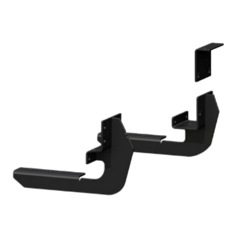
Product Photo
Front
Driver / left
fender
Passenger /
right fender
Torque Specifications
M6 bolt 3 ft-lbs.
Use above torque setting unless otherwise noted
Level of Difficulty
Easy
Installation difficulty levels are based on time
and effort involved and may vary depending on
the installer level of expertise, condition of the
vehicle and proper tools and equipment.
NOTICE
Visit www.ariesautomotive.com for a full-color copy of this
instruction manual, as well as helpful videos, guides and much more!
Before you begin installation, read all instructions thoroughly.
Proper tools will improve the quality of installation and reduce the time required.
Periodic inspection of your product should be performed
to ensure all hardware and / or components remain secure.
To help prevent damage to the product or vehicle, refer to the specified
torque specifications when securing hardware during the installation process.
ARIESAUTOMOTIVE.COM •PRODUCT SUPPORT: 877.287.8634 •2500207-INS-RA •12/30/2022 •ECN9916 •PAGE 2
PROCEDURE:
REMOVE CONTENTS FROM BOX. VERIFY ALL PARTS ARE PRESENT. READ INSTRUCTIONS
CAREFULLY. CUTTING AND MODIFICATION IS REQUIRED TO REINSTALL THE PLASTIC FENDER
LINER. DRILLING IS REQUIRED. ASSISTANCE IS RECOMMENDED.
1. Start installation on the Driver/Left side of the vehicle. Release the plastic clips and remove any
hardware attaching the liner to the outer edge and underside of the fender and the body, (Figure 1).
Remove the inner fender liner.
2. Next, firmly pull the fender straight outward from the body to pop the clips from the mounting holes,
(Figure 2). Remove any clips left attached to the body panel and move the fender to a smooth, clean
surface.
3. Use an electric drill and 25/64” drill bit, (not included) to drill out the mounting hole in the front of the
wheel well the body (Figures 3 & 4). VERY IMPORTANT: Only drill through the outer sheet metal to
enlarge the holes for a Threaded Insert, do not drill completely through the body.
a. Select the 6mm Threaded Insert Installation Tool and (1) 6mm Threaded Insert, (Figure 6-A).
b. Screw the Insert onto the threaded end of the Insert Tool, (Figure 6-A).
c. Firmly hold the Tool and push the Insert into one of the drilled holes, (Figure 6-B).
d. Insert should fit snug into the drilled hole. Lightly tap the Tool and Insert into the hole with a
small hammer if necessary.
e. Firmly hold the hex nut on the Insert Tool in place with a wrench and turn the hex bolt clockwise
to tighten the bolt and expand the Insert in the hole (Figure 6-C).
f. Once Insert is fully compressed and expanded, remove the Tool from the Insert. WARNING: Do
not overtighten Insert or damage to the Insert may result.
4. With assistance, hold the Fender up in position. Attach the Fender to the previously installed Threaded
Insert with (1) 6mm Button Head Bolts, (1) 6mm Lock Washers and (1) 6mm Flat Washers, (Figure 7).
Do not tighten hardware at this time.
5. Next, attach the Fender to the (7) remaining mounting locations with access tothe back of the outer
body panel. Attach the Fender to the (7) locations with (7) 6mm Button Head Bolts, (7) 6mm Lock
washers, (7) 6mm Flat Washers and (7) 6mm Flange Nuts, (Figures 5, 7—9). Do not tighten hardware
at this time.
6. With the fender in place, determine if plastic fender liner will be reinstalled
a. Slide fender liner into position.
b. Trim the outer section from the liner. NOTE: Actual amount to remove from liner to be
determined by installer. Leave as many mounting points on the plastic liner as possible.
c. Reinstall modified plastic fender liner if desired.
7. Adjust the position of the Fender and fully tighten all hardware.
8. Repeat Steps 1—7 to attach the Passenger/Right Fender.
9. Do periodic inspections to the installation to make sure that all hardware is secure and tight.
To protect your investment, Do not use any type of polish or wax that may contain abrasives that could damage the
finish. Mild soap may be used to clean the Fenders.

ARIESAUTOMOTIVE.COM •PRODUCT SUPPORT: 877.287.8634 •2500207-INS-RA •12/30/2022 •ECN9916 •PAGE 3
Driver/Left Side Installation Pictured
(Fig 1) Release clips and all hardware
attaching inner fender liner to outer
fender (Passenger/Right side shown)
Front
(Fig 2) Firmly pull fender straight out from
vehicle. Remove any clips still attached to body
Front
(Fig 5) Do not drill these (7) mounting locations.
NOTE: The (7) mounting locations can be
accessed from between body panels
Front
(Fig 3) Drill 25/64” hole in body panel at front
location (arrow) NOTE: The mounting location
cannot be accessed from between body panels
Front
(Fig 4) Drill the hole in the front of
the wheel well with a 25/64” drill bit
ARIESAUTOMOTIVE.COM •PRODUCT SUPPORT: 877.287.8634 •2500207-INS-RA •12/30/2022 •ECN9916 •PAGE 4
Driver/Left Side Installation Pictured
Front
(3) 6mm Button Head Bolts
(3) 6mm Lock Washers
(3) 6mm Flat Washers
(Fig 6) Assemble Threaded Insert Tool
(Fig 7) Attach the Passenger/Right
Fender to the front of the fender location
Front
(6-A) Select Insert Tool and (1) Insert. Thread Insert
onto end of Insert Tool. Hand tighten only, do not
tighten hex bolt
(6-B) Firmly hold assembly and push Insert into
drilled hole.
(6-C) Use a wrench (open or box end) to hold nut
(arrow) to prevent nut and tool from turning. Hold
Tool Assembly up tight in body panel. Turn hex bolt
in Tool clockwise to expand insert in body panel.
Remove Tool once Insert is fully tightened. Do not
overtighten or Insert may be damaged.
(2) 6mm
Flange Nuts
(Fig 9) Attach the Passenger/Right
Fender to the rear of the fender location
(3) 6mm Button Head Bolts
(3) 6mm Lock Washers
(3) 6mm Flat Washers
(3) 6mm Flange Nuts
(Fig 8) Attach the Passenger/Right
Fender to the top of the fender location
Front
(2) 6mm Button Head Bolts
(2) 6mm Lock Washers
(2) 6mm Flat Washers
(2) 6mm Flange Nuts

Other Lippert Automobile Accessories manuals

Lippert Vela Pop Up Use and care manual

Lippert

Lippert Vela Pop Up Use and care manual

Lippert Thule 5200 Use and care manual

Lippert

Lippert Thule 5200 Use and care manual

Lippert Vela Pop Up User manual

Lippert

Lippert Vela Pop Up User manual

Lippert Stargazer Spirit XTR User manual

Lippert

Lippert Stargazer Spirit XTR User manual

Lippert SolidStep 4.0 User manual

Lippert

Lippert SolidStep 4.0 User manual

Lippert ARIES S224050 User manual

Lippert

Lippert ARIES S224050 User manual

Lippert FLYSCREEN N Series User manual

Lippert

Lippert FLYSCREEN N Series User manual

Lippert CURT 45937 User manual

Lippert

Lippert CURT 45937 User manual

Lippert VELA POP-UP ROOF User manual

Lippert

Lippert VELA POP-UP ROOF User manual

Lippert Curt 18110 User manual

Lippert

Lippert Curt 18110 User manual

Lippert Curt 60654 User manual

Lippert

Lippert Curt 60654 User manual

Lippert Curt 18415 User manual

Lippert

Lippert Curt 18415 User manual

Lippert RV ENTRY DOOR User manual

Lippert

Lippert RV ENTRY DOOR User manual

Lippert JT's Strong Arm Installation instructions

Lippert

Lippert JT's Strong Arm Installation instructions

Lippert RV Instruction Manual

Lippert

Lippert RV Instruction Manual

Lippert Stargazer Nano Long Skylight User manual

Lippert

Lippert Stargazer Nano Long Skylight User manual

Lippert OneControl User manual

Lippert

Lippert OneControl User manual

Lippert 2021000090 Installation instructions

Lippert

Lippert 2021000090 Installation instructions

Lippert Power Steps 2.0 User manual

Lippert

Lippert Power Steps 2.0 User manual

Lippert Level-up User manual

Lippert

Lippert Level-up User manual

Lippert SMART BED UNIVERSAL KIT User manual

Lippert

Lippert SMART BED UNIVERSAL KIT User manual

Lippert Power Step 2.0 User manual

Lippert

Lippert Power Step 2.0 User manual

Lippert Promaster User manual

Lippert

Lippert Promaster User manual

Lippert Project 2000 Sliding Step User manual

Lippert

Lippert Project 2000 Sliding Step User manual

Popular Automobile Accessories manuals by other brands

Fleetworks FLTW-7632 installation instructions

Fleetworks

Fleetworks FLTW-7632 installation instructions

Steinhof O-116 FITTING AND OPERATION MANUAL

Steinhof

Steinhof O-116 FITTING AND OPERATION MANUAL

Rival 2D.2709.1-NL installation manual

Rival

Rival 2D.2709.1-NL installation manual

Dometic 9600011576 installation manual

Dometic

Dometic 9600011576 installation manual

JCROffroad JT Install instructions

JCROffroad

JCROffroad JT Install instructions

Camcar 40089 AL Mounting instructions

Camcar

Camcar 40089 AL Mounting instructions

DVB OFFROAD BRSB-01 installation manual

DVB

DVB OFFROAD BRSB-01 installation manual

Whispbar K745W Fitting instructions

Whispbar

Whispbar K745W Fitting instructions

Akyga AK-CH-09 user manual

Akyga

Akyga AK-CH-09 user manual

EGO Flash operating manual

EGO

EGO Flash operating manual

Phonocar VM268 instruction manual

Phonocar

Phonocar VM268 instruction manual

Suzuki 990E0-54P56-010 Installers and users instructions

Suzuki

Suzuki 990E0-54P56-010 Installers and users instructions

Over Armour Offroad CA-MAVERICKX3-4-TC01 Instructions for Installation and Care

Over Armour Offroad

Over Armour Offroad CA-MAVERICKX3-4-TC01 Instructions for Installation and Care

Atera SIGNO 044 141 User information

Atera

Atera SIGNO 044 141 User information

Scosche DO2110 Installation

Scosche

Scosche DO2110 Installation

Directed VW02 Firmware Specific Guide

Directed

Directed VW02 Firmware Specific Guide

Phonocar VM342 Mounting instructions

Phonocar

Phonocar VM342 Mounting instructions

Mitsubishi FUEL manual 

Mitsubishi

Mitsubishi FUEL manual 

manuals.online logo
manuals.online logoBrands
  • About & Mission
  • Contact us
  • Privacy Policy
  • Terms and Conditions

Copyright 2025 Manuals.Online. All Rights Reserved.