Makita EF1550RH User manual

Power Sprayer
EF1550RH
INSTRUCTION MANUAL
Important:
Read this instruction manual carefully before putting the Power Sprayer into operation and strictly observe
the safety regulations!
Preserve instruction manual carefully!

2
Thank you very much for purchasing the MAKITA Power Sprayer. We are
pleased to recommend to you the MAKITA Power Sprayer which is the result of
a long development programme and many years of knowledge and experience.
Please read this booklet which refers in detail to the various points that will
demonstrate its outstanding performance. This will assist you to obtain the best
possible result from your MAKITA Power Sprayer.
Table of Contents Page
Symbols.........................................................................2
Safety instructions .........................................................3
Technical data................................................................6
Designation of parts.......................................................7
Assembly instructions....................................................8
Before start of operation................................................9
Points in operation and how to stop ............................ 11
Operation.....................................................................13
Servicing instructions...................................................14
Storage........................................................................18
Take Particular care and attention!
Read instruction manual and follow
the warnings and safety precautions!
Forbidden!
No smoking!
No open ame!
Protective gloves must be worn!
Keep the area of operation clear of all
persons and pets!
Wear protective helmet, eye and ear
protection!
Engine-manual start
Emergency stop
ON/START
OFF/STOP
Recycling
Fuel (Gasoline)
First Aid
You will note the following symbols when reading the instructions manual.
SYMBOLS
Wear sturdy boots with nonslip soles.
Steeltoed safety boots are recommended!
English (Original instructions)

3
General Instructions
– To ensure correct operation, user has to read this instruction manual to make
himself familiar with the handling of the Power Sprayer. Users insufciently
informed will risk danger to themselves as well as others due to improper
handling.
– It is recommended only to lend the Power Sprayer to people who have
proven to be experienced with Power Sprayers.
Always hand over the instruction manual.
– First users should ask the dealer for basic instructions to familiarize oneself
with the handling of an Power Sprayer.
– Children and young persons aged under 18 years must not be allowed to
operate the Power Sprayer. Persons over the age of 16 years may however
use the device for the purpose of being trained only whilst under supervision
of a qualied trainer.
– Use Power Sprayers with the utmost care and attention.
– Operate the Power Sprayer only if you are in good physical condition.
Perform all work calmly and carefully. The user has to accept liability for
others.
– Never use the Power Sprayer after consumption of alcohol or drugs, or if
feeling tired or ill.
Intended use of the machine
– The Power Sprayer is designed for use in controlling vegetation and
eradication of insects. Do not use this sprayer for any other purpose.
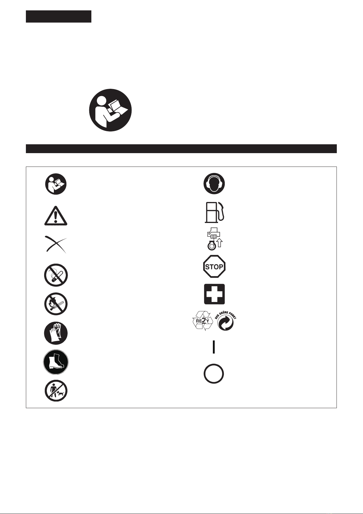
Personal protective equipment
– Please wear clothing that is functional and tight-tting, without restricting
movement when operating the Power Sprayer. Do not wear clothing or
jewelry that could get tangled with foliage or the machine.
– For adequate protection against head, eye, feet, hand, and hearing injuries,
the following protective equipment and clothing must be used when working
with the Power Sprayer.
1. Always wear adequate face protection (mask, protective goggles, etc.) to
protect the face, eyes and lungs from dust and chemicals.
2. To avoid hearing damage, wear adequate hearing protection at all times.
3. To protect skin from dust and chemicals, wear work clothes with long
sleeves and long pants at all times.
4. Always wear rubber gloves when operating or servicing the Power Sprayer.
5. When using the Power Sprayer, always wear sturdy shoes with non-slip
soles. Special work shoes are available to ensure good footing and protect
against injury.
– Always secure loose clothing, hair, and accessories such as towels etc.
Loose objects may become tangled in moving parts of the machine and
cause serious injury.
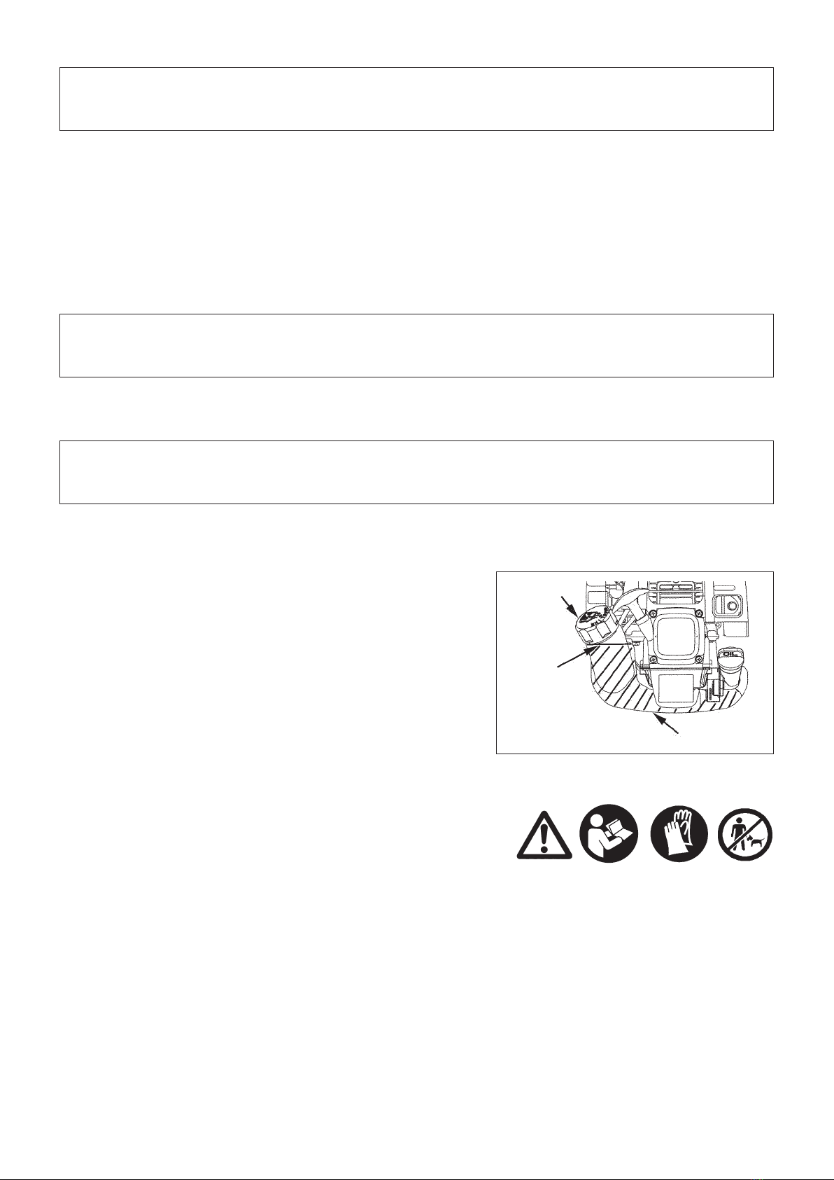
Starting up the Power Sprayer
– Please make sure that there are no children or other people within a working
range of 15 meters (50 ft), also pay attention to any animals in the working
vicinity.
– Before use always check that the Power Sprayer is safe for operation:
Check to make sure the control lever operates smoothly.
– Check for clean and dry handles and test the function of the start/stop switch.
SAFETY INSTRUCTIONS
Protective
mask
Ear protection
Protective
goggles
Long sleeves
Rubber
gloves
Long pants
Work shoes
Waterproof cap
360°
15 meters
15 meters

4
Start the Power Sprayer only in accordance with the instructions.
– Do not use any other methods for starting the engine!
– Use the Power Sprayer and the tools only for such applications as specied.
– Only start the Power Sprayer engine, after the entire assembly is done.
Operation of the device is only permitted after all the appropriate accessories
are attached!
– The engine is to be switched off immediately in case of any engine problems.
– During operation always hold the grip with both hands.
Always ensure a safe footing.
– Operate the Power Sprayer in such a manner as to avoid inhalation of
the exhaust gases. Never run the engine in enclosed rooms (risk of gas
poisoning). Carbon monoxide is an odorless gas.
– Switch off the engine when resting and when leaving the Power Sprayer
unattended, and place it in a safe location to prevent danger to others or
damage to the machine.
– Never put the hot Power Sprayer onto dry grass or onto any combustible
materials.
– Never operate the engine with faulty exhaust mufer.
– Shut off the engine during transport.
– During transport over long distances the tool protection included with the
equipment must always be used.
– Ensure safe position of the Power Sprayer during car transportation to avoid
fuel leakage.
– When transporting the Power Sprayer, ensure that the fuel tank is completely
empty.
– When unloading the Power Sprayer from the truck, never drop the Engine to
the ground or this may severely damage the fuel tank.
– Except in case of emergency, never drop or cast the Power Sprayer to the
ground or this may severely damage the Power Sprayer.
– Remember to lift the entire equipment from the ground when moving the
equipment. Dragging the fuel tank is highly dangerous and will cause damage
and leakage of fuel, possibly causing re.
Refuelling
– Shut off the engine during refuelling, keep away from open ames and do not
smoke.
– Avoid skin contact with mineral oil products. Do not inhale fuel vapor. Always
wear protective gloves during refuelling. Change and clean protective clothing
at regular intervals.
– Take care not to spill either fuel or oil in order to prevent soil contamination
(environmental protection). Clean the Power Sprayer immediately after fuel
has been spilt.
– Avoid any fuel contact with your clothing. Change your clothing instantly if
fuel has been spilt on it (to prevent clothing catching re).
– Inspect the fuel cap at regular intervals making sure that it can be securely
fastened and does not leak.
– Carefully tighten the fuel tank cap. Change location to start the engine (at
least 3 meters away from the place of refuelling).
– Never refuel in closed rooms. Fuel vapors accumulate at ground lever (risk of
explosions).
– Only transport and store fuel in approved containers. Make sure the fuel
stored is not accessible to children.
• Resting
• Transport
• Refuelling
• Maintenance
• Tool replacement
3 meters

5
Packaging
The MAKITA Power Sprayer will be delivered in two protective cardboard boxes
to prevent transport damage. Cardboard is a basic raw material and is therefore
consequently reusable or suitable for recycling (waste paper recycling).
Observe the relevant accident prevention instructions issued by the relevant
trade associations and by the insurance companies.
Do not perform any modications on the Power Sprayer as this will endanger
your safety.
The performance of maintenance or repair work by the user is limited to those
activities as described in the instruction manual. All other work is to be done by
an Authorized Service Agent. Use only genuine spare parts and accessories
released and supplied by MAKITA.
Use of non-approved accessories and tools means increased risk of accidents.
MAKITA will not accept any liability for accidents or damage caused by the use
of non-approved Power Sprayer, or accessories.
First Aid
In case of accident make sure that a rst-aid box is available in the vicinity of
the spraying operations. Immediately replace any item taken from the rst aid
box.
When asking for help, please give the following
information:
– Place of accident
– What happened
– Number of injured persons
– Kind of injuries
– Your name

6
TECHNICAL DATA EF1550RH
Model EF1550RH
Dimensions: length x width x height mm 345 x 395 x 570
Mass kg 7.4
Volume (fuel tank) L 0.6
Volume (oil tank) L 0.08
Engine displacement cm324.5
Maximum fuel consumption kg/h 0.33
Maximum specic fuel consumption g/kwh 408
Idling speed min-1 3,400
Carburetor type WALBRO WYL
Ignition system type Solid state ignition
Spark plug type NGK CMR4A
Electrode gap mm 0.7 - 0.8
Fuel Automobile gasoline
Engine Oil SAE 10W-30 oil of API Ciassication,
Class SF or higher (4-stroke engine for automobile)
Pump type Rotary type
Maximum pressure MPa 1.2
Tank capacity (chemical) L 15

7
①
③⑥
⑯
②
DESIGNATION OF PARTS
GB DESIGNATION OF PARTS
1 Fuel tank
2 Rewind starter
3 Air cleaner
4 I-O switch (on/off)
5 Spark plug
6Exhaust mufer
7 Chemical tank
8 Chemical tank cap
9 Nozzle
10 Nozzle pipe
11 Control lever
12 Control cable
13 Spray hose
14 Nozzle lever
15 Nozzle pipe holder
16 Fuel ller cap
17 Starter knob
18 Exhaust pipe
19 Oil cap
⑰
⑲
⑱
⑫
⑬
⑭⑮
⑩
⑨
④
⑪
⑤
⑦
⑧

8
CAUTION: Before performing any work on the Power Sprayer, always switch off
the motor and pull the spark plug connectors off the spark plug.
Always wear protective gloves!
CAUTION: Start the Power Sprayer only after having assembled it completely.
ASSEMBLY INSTRUCTIONS
1. ASSEMBLY OF NOZZLE
Refer to the gure on the previous page (DESIGNATION OF PARTS) to assemble handgrip, nozzle lever, nozzle pipe and nozzle. Be careful to
put parts together properly to prevent leaks.
2. SETTING OF SHOULDER HARNESS
Set the two shoulder harnesses on a chemical tank in a way shown below without any twists of the shoulder harnesses. Instructions are given
about the ones for one of the shoulder harnesses.
Setting upper part of shoulder harness
123
Setting lower part of shoulder harness
1 2
3
Pull the harness in the direction of
the arrow and put its folded end at
the lower end of the buckle.
Chemical tank
Upper buckle
A
A
A
Upper buckle
Lower buckle
Chemical tank
Put the back harnesses ‘A’. one of the twooverlapped
harnesses, at the metallic hook in a way shown below
at 2 and 3.
Metallic hook
Repeat the same instructions for the other
shoulder harness to nish the setting.
Metallic hook
Put the part 'A', of the harness through
this gap of the metallic hook.
Then raise the harness to
the degree of 90, in the
direction of the arrow.

9
Inspection and rell of engine oil
– Perform the following procedure, with the engine cooled down.
– Set the engine level, remove oil cap (Fig. 1), and check to see whether or not there is oil in the range between the upper limit and lower limit
marks of the oil pipe (Fig. 2).
– Top up with oil to upper limit mark if oil is insufcient (oil level is close to lower limit mark) (Fig. 3).
– The area surrounding the external marks is transparent, so the amount of oil inside can be checked without having to remove the oil cap.
However, if oil pipe becomes extremely dirty, visibility may be lost, and oil level will have to be checked against stepped section on inside of
oil pipe.
– For reference, the oil rell time is about 10h (10 times or 10 tanks of oil rell).
If the oil changes in color or mixes with dirt, replace it with new one. (For the interval and method of replacement, refer to P 15)
Recommended oil: SAE 10W-30 oil of API Classication, Class SF or higher (4-stroke engine for automobile)
Oil volume: Approx. 0.08L
Note: If the engine is not kept upright, oil may go into around the engine, and may be relled excessively.
If the oil is lled above the limit, the oil may be contaminated or may catch re with white smoke.
Point 1 in Replacement of oil: “Oil gauge”
– Remove dust or dirt near the oil rell port, and detach the oil gauge.
– Keep the detached oil gauge free of sand or dust. Otherwise, any sand or dust adhering to the oil gauge may cause irregular oil
circulation or wear on the engine parts, which will result in troubles.
Fig. 1 Fig. 2 Oil pipe Fig. 3
BEFORE START OF OPERATION
(1) Keep the engine level, and detach the oil cap.
(2) Fill with oil to upper limit mark. (see Fig. 3)
Use oil bottle when lling.
(3) Securely tighten the oil cap. Insufcient tightening may cause oil leakage.
Internal stepped
section (upper
limit)
External mark
(lower limit)
Internal stepped
section (lower
limit)
External mark
(upper limit)
Oil
Top up with oil until
oil level reaches
internal stepped
section (upper
limit). The area between the
external upper and lower
limits is transparent, so
oil level can be checked
externally against these
marks.
Oil cap
Oil pipe

10
MIXING AGURICULTUAL CHEMICALS
1) Mixing aguricultual chemicals
1. Aguricultual chemicals are toxic. When working with aguricultual chemicals, strictly
follow the instructions provided by the manufacturer at all times.
2. Always use the provided strainer when pouring aguricultual chemicals into the
chemical tank.
3. Firmly tighten the chemical tank cap to prevent leaks.
4. If chemicals are to be mixed inside the chemical tank, alwys add water before other
sguricultual chemicals.
CAUTION:
● Always handle agricultural chemicals with the utmost care. Should your skin come into contact with agricultural chemicals by accident,
immediately rinse the affected area with large amounts of water.
2) Using a different type of chemical agent
1. Take extra care to thoroughly rinse the sprayer tank, pump and nozzle before adding different chemical agents to the sprayer tank. Mixing
the residues of previously used agricultural chemicals with other chemical agents may cause toxin-induced diseases.
Refueling
WARNING: INFLAMMABLES STRICTLY PROHIBITED
Gasoline used: Automobile gasoline (unleaded gasoline)
– Loosen the tank cap a little so that there will be no difference in atmospheric
pressure.
– Detach the tank cap, and refuel, discharging air by tilting the fuel tank so
that the refuel port will be oriented upward. (Never rell fuel full to the oil rell
port.)
– Wipe well the periphery of the tank cap to prevent foreign matter from
entering into the fuel tank.
– After refueling, securely tighten the tank cap.
● If there is any aw or damage on the tank cap, replace it.
● The tank cap is consumable, and therefore should be renewed every two to
three years.
Fuel
The engine is a four-stroke engine. Be sure to use an automobile gasoline (regular gasoline or premium gasoline).
Point 2 in Replacement of oil: “If oil spills out”
– If oil spills out between the fuel tank and engine main unit, the oil is sucked into through the cooling air intake port, which will
contaminate the engine. Be sure to wipe out spilt oil before start of operation.
STORAGE OF MACHINE AND REFILL TANK
– Keep the machine and tank at a cool place free from direct sunshine.
– Never keep the fuel in the cabin or trunk.
Points for fuel
– Never use a gasoline mixture which contains engine oil. Otherwise, it will cause excessive carbon accumulation or mechanical troubles.
– Use of deteriorated oil will cause irregular startup.
REFUELING
Handling of fuel
It is necessary to handle fuel with utmost care. Fuel may contain substances similar to solvents. Refueling must be performed in a sufciently
ventilated room or in the open air. Never inhale fuel vapor, and keep fuel away from you. If you touch fuel repeatedly or for a long time, the
skin becomes dry, which may cause skin disease or allergy. If fuel enters into the eye, clean the eye with fresh water. If your eye remains still
irritated, consult your doctor.
Storage period of fuel
Fuel should be used up within a period of 4 weeks, even if it is kept in a special container in a well-ventilated shade.
If a special container is not used or if the container is not covered, fuel may deteriorate in one day.
Fuel tank cap
Fuel upper limit
Fuel tank

11
Observe the applicable accident prevention regulations!
A: Cold start
1) Set this machine on a at space.
2) Set the I-O switch to OPERATION.
3) Make sure that the throttle lever is the SLOW position.
POINTS IN OPERATION AND HOW TO STOP
WARNING:
● Do not start the engine at the fueling site. Always move at least three meters
away from fueling site and then start engine.
- Failure to do so may cause a re outbreak.
● Engine exhaust emissions are poisonous. Do not use the sprayer in poorly
ventilated locations, such as indoors or in tunnels, etc.
- If the sprayer is used in a poorly ventilated location, exhaust gas poisoning
may occur.
● After starting the engine, if an abnormal noise, smell and/or vibration is
noticed, switch off engine immediately, and investigate the cause.
- If the sprayer is used while such an abnormality is occurring, an accident
may occur.
● When operating the switch to stop engine, be sure to check that engine has
stopped.
CAUTION:
● Always put chemical in chemical tank before starting engine for use (to
prevent no-load running). At this time, also check that the spray valve is
closed.
Nozzle lever
Closed
Carburetor
Primer pump
5) Primer pump
Continue to push the primer pump until fuel enters into the primer pump. (In
general, fuel enters into the primer pump by 7 to 10 pushes.)
If the primer pump is pushed excessively, an excess of gasoline returns to
the fuel tank.
Closed
4) Choke lever
Close choke lever.
Choke opening
- During cold spells or when engine is cold, open the choke fully.
- When restarting engine directly after use, open choke halfway or fully.
Throttle lever
SLOW
I-O switch
I (ON)

12
Note: In case of excessive fuel intake, remove the spark plug and pull the starter handle slowly to remove excess fuel. Also, dry the electrode
section of the spark plug.
8) Warm-up operation
Continue warm-up operation for 2 to 3 minutes.
Open
6) Recoil starter
Pull the start knob gently until it is hard to pull (compression point). Then,
return the start knob, and pull it strongly.
Never pull the rope to the full. Once the start knob is pulled, never release
your hand immediately. Hold the start knob until it returns to its original
point.
7) Choke lever
Open the choke lever if engine begins to startup.
- Gradually open the choke lever according to the state of the engine, but
always open fully in the end.
- Suddenly pulling the choke lever open during a cold spell or when the
engine is cold may stop the engine.
Please use the choke lever with care.

13
B: Startup after warm-up operation
1) Push the primer pump repeatedly.
2) Keep the throttle lever at the idling position.
3) Pull the recoil starter strongly.
4) If it is difcult to start the engine, open the throttle by about 1/3.
STOPPING
1) Close spray valve.
2) Set throttle lever to low speed (idling position).
3) Set stop switch to stop position.
ADJUSTMENT OF LOW-SPEED ROTATION (IDLING)
When it is necessary to adjust the low-speed rotation (idling), perform it by the carburetor adjusting screw.
OPERATION
CHECKUP OF LOW-SPEED ROTATION
– Set the low-speed rotation to 3,400 min-1.
If it is necessary to change the rotation speed, regulate the adjusting screw
(illustrated on the right), with Phillips screwdriver.
– Turn the adjusting screw to the right, and the engine rotation will increase.
Turn the adjusting screw to the left, and the engine rotation will drop.
– The carburetor is generally adjusted before shipment. If it is necessary to
readjust it, please contact Authorized Service Agent.
1) Once the engine starts, adjust the length of the shoulder straps so that the
sprayer will be as near to your body as possible, and then set the sprayer
on your back.
Using one-touch shoulder straps
Strap length is adjusted in the following ways.
● Loosening strap
(1) Raise buckle.
(2) Pull the side of the strap that is attached to the sprayer.
● Tightening strap
(3) Pull the unattached end of the strap.
Note: When tightening strap, the strap will move comparatively smoothly
if there is no load (weight) on the strap.
2) Use the throttle lever to adjust the amount of spray according to the spray
work involved.
* The amount of spray also can be adjusted by using the spray valve.
CAUTION:
● If possible, spray downwind, and take full care not to get chemical liquid on
your body.
(3) Tighten
Buckle
(2) Loosen
(1)
Nozzle lever
Closed
Throttle lever
SLOW
I-O switch
O (OFF)
Carburetor
Primer pump

14
– Only use the Power Sprayer in good light and visibility conditions. Never use
the Power Sprayer at night. Do not use the Power Sprayer during rainfall or
immediately after rain (danger of injury through slipping and falling in wet
conditions).
– Beware of slippery and wet areas (ice and snow) as there is a danger of
slipping, and always ensure secure footing.
– Never use the Power Sprayer while standing on a ladder.
– Never climb a tree to use the Power Sprayer from the tree.
– Never use the Power Sprayer while standing on an unstable surface.
– Do not point the nozzle of the Power Sprayer towards people or animals.
Flying debris may cause serious injury.
– Do not touch the spark plug connector while the engine is running.
– Do not touch moving parts of the Power Sprayer while the engine is running.
– Do not touch the mufer or other engine parts during operation or for a period
after the engine has stopped. These engine parts are extremely hot and may
cause serious burns.
– Ensure that the toxicity of the pesticides or herbicides to be used is known
before use, and carefully read related use instructions to familiarize yourself
with the proper procedures for using the chemicals in question. If pesticides/
herbicides come in contact with your skin, immediately rinse the affected area
and thoroughly wash with soap. Firmly tighten the cap of the sprayer tank in
order to avoid chemical leaks.
If spray is interrupted, or force weakens, and/or engine suddenly starts to rev
high, the chemical tank is empty. Close spray valve, reduce engine revs, stop
engine, and then replenish chemical.
CAUTION: Before doing any work on the Power Sprayer, always stop the engine and pull the plug cap off the spark plug (see “checking the
spark plug”).
Always wear protective gloves!
To ensure a long service life and to avoid any damage to the equipment, the following servicing operations should be performed at regular
intervals.
Daily checkup and maintenance
– Before operation, check the machine for loose screws or missing parts.
– Before operation, always check for clogging of the cooling air passage and the cylinder ns.
Clean them if necessary.
– Perform the following work daily after use:
• Clean the Power Sprayer externally and inspect for damage.
• Clean the air lter. When working under extremely dusty conditions, clean the lter the severall times a day.
– Check the functioning of the I-O switch, the lock-off lever, the control lever, and the look button.
SERVICING INSTRUCTIONS

15
REPLACEMENT OF ENGINE OIL
Deteriorated engine oil will shorten the life of the sliding and rotating parts to a great extent. Be sure to check the period and quantity of
replacement.
ATTENTION: In general, the engine main unit and engine oil still remain hot just after the engine is stopped. In replacement of oil,
conrm that the engine main unit and engine oil are sufciently cooled down. Otherwise, there may remain a risk of
scald.
Note: If the oil lled above the limit, it may be contaminated or may catch re with white smoke.
Interval of replacement: Initially, every 20 operating hours, and subsequently every 50 operating hours
Recommended oil: SAE10W-30 oil of API Classication SF Class or higher (4-stroke engine oil for automobile)
1) Remove drain bolt. At this time, be sure not to mislay drain bolt’s gasket.
Also, be sure to place both items in a clean location where they will not
become dirty.
Drain bolt
Gasket
Oil drain hole
Upper limit mark
Oil
2) Remove drain bolt and then remove oil cap to drain out oil from drain hole.
3) Once the oil has been drained, combine gasket and drain bolt, and tightly
secure drain bolt, so that it will not loosen and cause leaks.
* Use cloth to fully wipe off any oil attached to bolt and equipment.
4) Set the engine level, and gradually ll up to upper limit mark with new oil.
5) After lling, tightly secure oil cap, making sure that it does not become
loose. If oil cap becomes loose, oil may leak out.
POINTS ON OIL
– Never discard replaced engine oil in garbage, earth or sewage ditch. Disposal of oil is regulated by law. In disposal, always follow the
relevant laws and regulations. For any points remaining unknown, contact Authorized Service Agent.
– Oil will deteriorate even when it is kept unused. Perform inspection and replacement at regular intervals (replace with new oil every 6
months).

16
CLEANING OF AIR CLEANER
DANGER: INFLAMMABLES STRICTLY PROHIBITED
Interval of Cleaning and Inspection: Daily (every 10 operating hours)
– Remove the air cleaner cover attachment bolt.
– Pull the bottom of the cover to remove the air cleaner cover.
– Fully close choke lever to prevent dust and dirt getting into carburetor.
When element (sponge) becomes dirty with oil, squeeze it with full force.
– When the element (sponge) is extremely dirty, remove it, and wash in neutral
detergent diluted with warm or cold water, and dry thoroughly.
– Reassemble the element after thorough drying. Insufciently dried element
may cause poor engine starting.
– Use rag to wipe off oil from around area of air cleaner cover and plate’s
breather section.
– As soon as cleaning is nished, replace air cleaner cover, and tightly secure
bolt. (For mounting, clip on upper hook edge and then clip on lower hook
edge.)
Points in Handling Air Cleaner Element
– Clean the element several times a day, if excessive dust adheres to it.
– If operation continues with the element remaining not cleared of oil, oil
in the air cleaner may fall outside, resulting in oil contamination.
CLEANING OF FUEL FILTER
WARNING: INFLAMMABLES STRICTLY PROHIBITED
Interval of Cleaning and Inspection: Monthly (every 50 operating hours)
Suction head in the fuel tank
– The fuel lter (1) of the suction head is used to lter the fuel required by the
carburetor.
– A periodical visual inspection of the fuel lter is to be conducted. For that
purpose open the tank cap, use a wire hook and pull out the suction head
through the tank opening. Filters found to have hardened, been polluted or
clogged up are to be replaced.
– Insufcient fuel supply can result in the admissible maximum speed being
exceeded. It is therefore important to replace the fuel lter at least quarterly to
ensure satisfactory fuel supply to the carburetor.
0.7 mm - 0.8 mm
(0.028” - 0.032”)
CHECKING THE SPARK PLUG
– Only use the supplied universal wrench to remove or to install the spark plug.
– The gap between the two electrodes of the spark plug should be 0.7 - 0.8 mm
(0.028” - 0.032”). If the gap is too wide or too narrow, adjust it. If the spark
plug is clogged or contaminated, clean it thoroughly or replace it.
CAUTION: Never touch the spark plug connector while the engine is running
(danger of high voltage electric shock).
Fuel pipe
Hose
clamp
Fuel lter
Air cleaner cover
Plate Choke lever
Breather section
Attachment bolt
Element
(sponge)

17
REPLACEMENT OF FUEL PIPE
CAUTION: INFLAMMABLES STRICTLY PROHIBITED
Interval of Cleaning and Inspection: Daily (every 10 operating hours)
Replacement: Annually (every 200 operating hours)
Replace the fuel pipe every year, regardless of operating frequency. Fuel
leakage may lead to re.
If any leakage is detected during inspection, replace the oil pipe immediately.
INSPECTION OF BOLTS, NUTS AND SCREWS
– Retighten loose bolts, nuts, etc.
– Check for fuel and oil leakage.
– Replace damaged parts with new ones for safety operation.
CLEANING OF PARTS
– Keep the engine always clean.
– Keep the cylinder ns free of dust or dirt. Dust or dirt adhering to the ns will
cause piston seizure.
Fuel pipe
REPLACEMENT OF GASKETS AND PACKINGS
In reassembling after the engine is dismounted, be sure to replace the gaskets and packings with new ones.
Any maintenance of adjustment work that is not included and described in this manual is only to be performed by Authorized Service Agents.
– Be kind to the environment. Operate the Power Sprayer with as little noise and pollution as possible. In particular check the correct
adjustment of the carburetor.
– Clean the Power Sprayer at regular intervals and check that all screws and nuts are securely tightened.
– Never service or store the Power Sprayer in the vicinity of open ames, sparks, etc.
– Always store the Power Sprayer in a well-ventilated locked room and with an emptied fuel tank.

18
WARNING: When draining the fuel, be sure to stop the engine and conrm that the engine cools
down.
Just after stopping the engine, it may still hot with possibility of burns, inammability and re.
ATTENTION: When the machine is kept out of operation for a long time, drain up all fuel from the
fuel tank and carburetor, and keep it at a dry and clean place.
Fault location
– Drain up fuel from the fuel tank and carburetor according to the following
procedure:
1) Remove the fuel tank cap, and drain fuel completely.
If there is any foreign matter remaining in the fuel tank, remove it
completely.
2) Pull out the fuel lter from the rell port using a wire.
3) Push the primer pump until fuel is drained from there, and drain fuel
coming into the fuel tank.
4) Reset the lter to the fuel tank, and securely tighten the fuel tank cap.
5) Then, continue to operate the engine until it stops.
– Remove the spark plug, and drip several drops of engine oil through the
spark plug hole.
– Gently pull the starter handle so that engine oil will spread over the engine,
and attach the spark plug.
– During storage, keep the rod horizontal or keep the machine upright with the
branch edge oriented upward. (In this case, pay full attention to prevent the
machine from falling.)
– Keep the drained fuel in a special container in a well-ventilated shade.
Drain fuel Humidity
STORAGE
Attention after long-time storage
– Before startup after long-time shutdown, be sure to replace oil (refer to P 15). Oil will deteriorate while the machine is kept out of
operation.
Fault System Observation Cause
Engine not starting or with
difculty
Ignition system Ignition spark O.K. Fault in fuel supply or compression system, mechanical
defect
No ignition spark STOP-switch operated, wiring fault or short circuit, spark
plug or connector defective, ignition module faulty
Fuel supply Fuel tank lled Carburetor defective, fuel supply line bent or blocked,
fuel dirty
Compression No compression when
pulled over
Cylinder bottom gasket defective, crankshaft seals
damaged, cylinder or piston rings defective or improper
sealing of spark plug
Mechanical fault Starter not engaging Broken starter spring, broken parts inside of the engine
Warm start problems Tank lled ignition spark
existing
Carburetor contaminated, have it cleaned
Engine starts but dies Fuel supply Tank lled Incorrect idling adjustment, carburetor contaminated
Fuel tank vent defective, fuel supply line interrupted,
cable or STOP-switch faulty
Insufcient performance Several systems may
simultaneously be
affected
Engine idling poor Air lter contaminated, carburetor contaminated, mufer
clogged, exhaust duct in the cylinder clogged

19
*1 Perform initial replacement after 20h operation.
*2 For the 200 operating hour inspection, request Authorized Service Agent or a machine shop.
*3 After emptying the fuel tank, continue to run the engine and drain fuel in the carburetor.
Operating time
Item
Before
operation
After
lubrication
Daily
(10h) 30h 50h 200h
Shutdown/
rest
Corres-
ponding P
Engine oil
Inspect/clean 9
Replace *115
Tightening parts
(bolt, nut) Inspect 17
Fuel tank
Clean/inspect —
Drain fuel *318
Throttle lever Check function —
Stop switch Check function 13
Low-speed rotation Inspect/adjust 13
Air cleaner Clean 16
Ignition plug Inspect 16
Cooling air duct Clean/inspect 16
Fuel pipe
Inspect 16
Replace *2—
Fuel lter Clean/replace 16
Clearance between air intake
valve and air discharge valve Adjust *2—
Engine overhaul *2—
Carburetor Drain fuel *318

State of abnormality Probable cause (malfunction) Remedy
Engine does not start
Failure to operate primer pump Push 7 to 10 times
Low pulling speed of starter rope Pull strongly
Lack of fuel Feed fuel
Clogged fuel lter Clean
Broken fuel tube Straighten fuel tube
Deteriorated fuel Deteriorated fuel makes starting more difcult.
Replace with new one. (Recommended
replacement: 1 month)
Excessive suction of fuel Set throttle lever from medium speed to high
speed, and pull starter handle until engine
starts.
If engine will not start still, remove spark plug,
make electrode dry, and reassemble them as
they originally are. Then, start as specied.
Detached plug cap Attach securely
Contaminated spark plug Clean
Abnormal clearance of spark plug Adjust clearance
Other abnormality of spark plug Replace
Abnormal carburetor Make request for inspection and maintenance.
Starter rope cannot be pulled Make request for inspection and maintenance.
Abnormal drive system Make request for inspection and maintenance.
Engine stops soon
Engine speed does not increase
Insufcient warm-up Perform warm-up operation
Clogged fuel lter Clean
Contaminated or clogged air cleaner Clean
Abnormal carburetor Make request for inspection and maintenance.
Abnormal drive system Make request for inspection and maintenance.
Engine does not stop Detached connector Attach securely
Abnormal electric system Make request for inspection and maintenance.
Run engine at idling
TROUBLESHOOTING
Before making a request for repairs, check a trouble for yourself. If any abnormality is found, control your machine according to the description
of this manual. Never tamper or dismount any part contrary to the description. For repairs, contact Authorized Service Agent or local dealership.
When the engine does not start after warm-up operation:
If there is no abnormality found for the check items, open the throttle by about 1/3 and start the engine.
Makita Corporation
885513A0 www.makita.com
ALA
Table of contents
Other Makita Paint Sprayer manuals

Makita
Makita US053D User manual

Makita
Makita DVF104 User manual

Makita
Makita DUS108 User manual

Makita
Makita BVF154 User manual

Makita
Makita DUS108 User manual

Makita
Makita BVF104 User manual

Makita
Makita BVF104 Manual

Makita
Makita DUS054 User manual

Makita
Makita US053D User manual

Makita
Makita DUS054 User manual

Makita
Makita PM7651H User guide

Makita
Makita BVF104 User manual

Makita
Makita EVH2000 User guide

Makita
Makita EVH2000 User manual

Makita
Makita BVF104 User manual

Makita
Makita DUS108 User manual

Makita
Makita DUS054 User manual

Makita
Makita DUS108 User manual

Makita
Makita DVF104 User manual

Makita
Makita DUS108 User manual