Makita 4350T User manual

INSTRUCTION MANUAL
Jig Saw
4350T
4350CT
4350FCT
ENGLISH: Original instructions
O
DOUBLE INSULATION
Read before use.

2ENGLISH
SPECIFICATIONS
Model 4350T 4350CT 4350FCT
Length of stroke 26 mm 26 mm 26 mm
Max. cutting capacities Wood 135 mm 135 mm 135 mm
Steel 10 mm 10 mm 10 mm
Aluminum 20 mm 20 mm 20 mm
Strokes per minute (min-1)2,800 800 - 2,800 800 - 2,800
Overall length 236 mm 236 mm 236 mm
Net weight 2.7 kg 2.7 kg 2.7 kg
Safety class /II
• Duetoourcontinuingprogramofresearchanddevelopment,thespecicationshereinaresubjecttochange
without notice.
• Specicationsmaydifferfromcountrytocountry.
• Weight according to EPTA-Procedure 01/2014
Symbols
The following show the symbols used for the equip-
ment. Be sure that you understand their meaning before
use.
Read instruction manual.
DOUBLE INSULATION
Only for EU countries
Do not dispose of electric equipment
together with household waste material!
In observance of the European Directive,
on Waste Electric and Electronic
Equipment and its implementation in
accordance with national law, electric
equipment that have reached the end of
their life must be collected separately and
returned to an environmentally compatible
recycling facility.
Intended use
The tool is intended for the sawing of wood, plastic and
metal materials. As a result of the extensive accessory
and saw blade program, the tool can be used for many
purposes and is very well suited for curved or circular
cuts.
Power supply
The tool should be connected only to a power supply of
the same voltage as indicated on the nameplate, and
can only be operated on single-phase AC supply. They
are double-insulated and can, therefore, also be used
from sockets without earth wire.
Noise
The typical A-weighted noise level determined accord-
ing to EN62841-2-11:
Model 4350T
Sound pressure level (LpA) : 83 dB (A)
Sound power level (LWA) : 94 dB (A)
Uncertainty (K) : 3 dB (A)
Model 4350CT, 4350FCT
Sound pressure level (LpA) : 84 dB (A)
Sound power level (LWA) : 95 dB (A)
Uncertainty (K) : 3 dB (A)
NOTE: The declared noise emission value(s) has
been measured in accordance with a standard test
method and may be used for comparing one tool with
another.
NOTE: The declared noise emission value(s)
may also be used in a preliminary assessment of
exposure.
WARNING: Wear ear protection.
WARNING: The noise emission during actual
use of the power tool can differ from the declared
value(s) depending on the ways in which the
tool is used especially what kind of workpiece is
processed.
WARNING: Be sure to identify safety mea-
sures to protect the operator that are based on an
estimation of exposure in the actual conditions of
use (taking account of all parts of the operating
cycle such as the times when the tool is switched
off and when it is running idle in addition to the
trigger time).
Vibration
The vibration total value (tri-axial vector sum) deter-
mined according to EN62841-2-11:
Model 4350T
Work mode : cutting boards
Vibration emission (ah,B) : 7.0 m/s2
Uncertainty (K) : 1.5 m/s2
Work mode : cutting sheet metal
Vibration emission (ah,M) : 4.5 m/s2
Uncertainty (K) : 1.5 m/s2
Model 4350CT, 4350FCT
Work mode : cutting boards
Vibration emission (ah,B) : 7.5 m/s2
Uncertainty (K) : 1.5 m/s2
Work mode : cutting sheet metal
Vibration emission (ah,M) : 4.5 m/s2
Uncertainty (K) : 1.5 m/s2
NOTE: The declared vibration total value(s) has been
measured in accordance with a standard test method
and may be used for comparing one tool with another.
NOTE: The declared vibration total value(s) may also
be used in a preliminary assessment of exposure.

3ENGLISH
WARNING:
The vibration emission during actual
use of the power tool can differ from the declared val-
ue(s) depending on the ways in which the tool is used
especially what kind of workpiece is processed.
WARNING:
Be sure to identify safety measures
to protect the operator that are based on an estima-
tion of exposure in the actual conditions of use (tak-
ing account of all parts of the operating cycle such
as the times when the tool is switched off and when
it is running idle in addition to the trigger time).
EC Declaration of Conformity
For European countries only
The EC declaration of conformity is included as Annex A
to this instruction manual.
General power tool safety warnings
WARNING: Read all safety warnings, instruc-
tions, illustrations and specications provided
with this power tool. Failure to follow all instructions
listedbelowmayresultinelectricshock,reand/or
seriousinjury.
Save all warnings and instruc-
tions for future reference.
The term "power tool" in the warnings refers to your
mains-operated (corded) power tool or battery-operated
(cordless) power tool.
Work area safety
1. Keep work area clean and well lit. Cluttered or
dark areas invite accidents.
2. Do not operate power tools in explosive atmo-
spheres, such as in the presence of ammable
liquids, gases or dust. Power tools create sparks
which may ignite the dust or fumes.
3. Keep children and bystanders away while
operating a power tool. Distractions can cause
you to lose control.
Electrical Safety
1. Power tool plugs must match the outlet. Never
modify the plug in any way. Do not use any
adapter plugs with earthed (grounded) power
tools. Unmodiedplugsandmatchingoutletswill
reduce risk of electric shock.
2. Avoid body contact with earthed or grounded
surfaces, such as pipes, radiators, ranges and
refrigerators. There is an increased risk of elec-
tric shock if your body is earthed or grounded.
3. Do not expose power tools to rain or wet con-
ditions. Water entering a power tool will increase
the risk of electric shock.
4. Do not abuse the cord. Never use the cord for
carrying, pulling or unplugging the power tool.
Keep cord away from heat, oil, sharp edges
or moving parts. Damaged or entangled cords
increase the risk of electric shock.
5. When operating a power tool outdoors, use an
extension cord suitable for outdoor use. Use of
a cord suitable for outdoor use reduces the risk of
electric shock.
6. If operating a power tool in a damp location
is unavoidable, use a residual current device
(RCD) protected supply. Use of an RCD reduces
the risk of electric shock.
7. Use of power supply via an RCD with a rated
residual current of 30 mA or less is always
recommended.
8. Power tools can produce electromagnetic
elds (EMF) that are not harmful to the user.
However, users of pacemakers and other similar
medical devices should contact the maker of their
device and/or doctor for advice before operating
this power tool.
9. Do not touch the power plug with wet hands.
10. If the cord is damaged, have it replaced by the
manufacturer or his agent in order to avoid a
safety hazard.
Personal Safety
1. Stay alert, watch what you are doing and use
common sense when operating a power tool.
Do not use a power tool while you are tired or
under the inuence of drugs, alcohol or med-
ication. A moment of inattention while operating
powertoolsmayresultinseriouspersonalinjury.
2. Use personal protective equipment. Always
wear eye protection. Protective equipment such
as a dust mask, non-skid safety shoes, hard hat or
hearing protection used for appropriate conditions
willreducepersonalinjuries.
3. Prevent unintentional starting. Ensure the
switch is in the off-position before connecting
to power source and/or battery pack, picking
up or carrying the tool. Carrying power tools with
yourngerontheswitchorenergisingpowertools
that have the switch on invites accidents.
4. Remove any adjusting key or wrench before
turning the power tool on. A wrench or a key left
attached to a rotating part of the power tool may
resultinpersonalinjury.
5. Do not overreach. Keep proper footing and
balance at all times. This enables better control
of the power tool in unexpected situations.
6. Dress properly. Do not wear loose clothing or
jewellery. Keep your hair and clothing away
from moving parts.Looseclothes,jewelleryor
long hair can be caught in moving parts.
7. If devices are provided for the connection of
dust extraction and collection facilities, ensure
these are connected and properly used. Use of
dust collection can reduce dust-related hazards.
8. Do not let familiarity gained from frequent use
of tools allow you to become complacent and
ignore tool safety principles. A careless action
cancausesevereinjurywithinafractionofa
second.
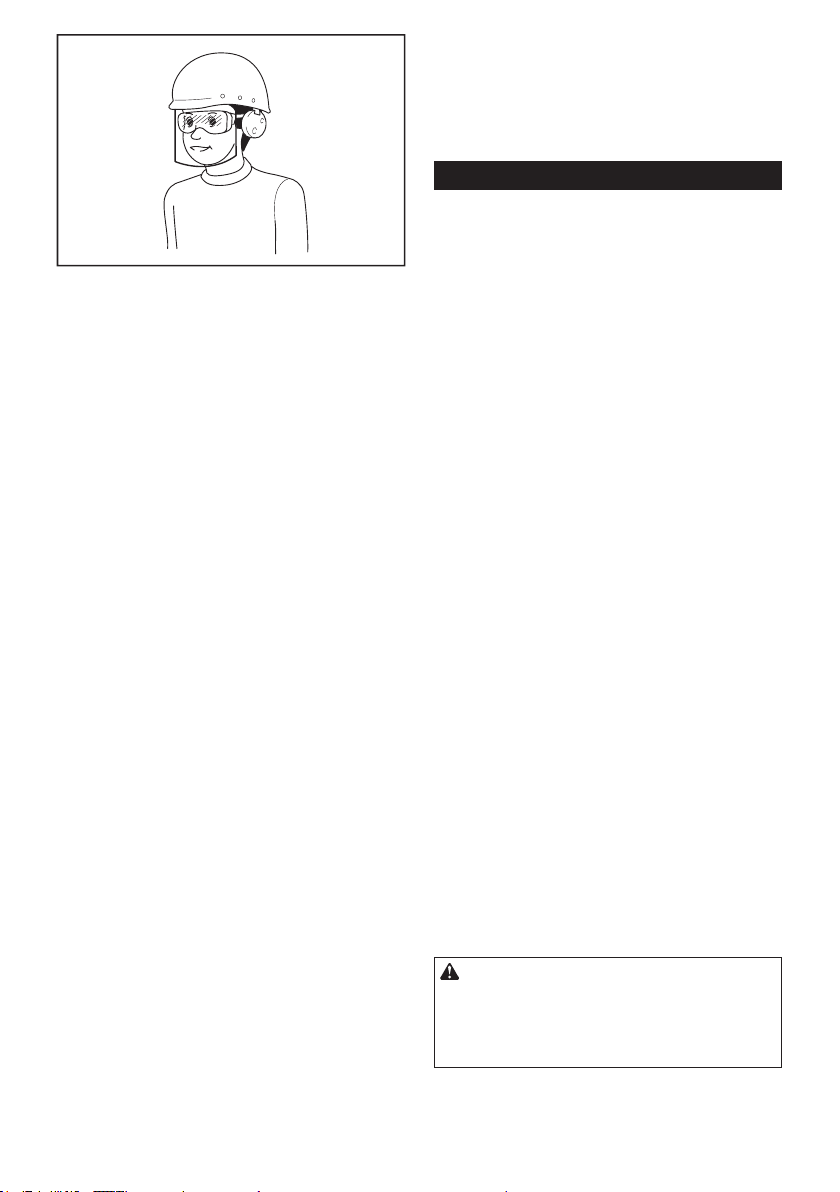
9. Always wear protective goggles to protect
your eyes from injury when using power tools.
The goggles must comply with ANSI Z87.1 in
the USA, EN 166 in Europe, or AS/NZS 1336
in Australia/New Zealand. In Australia/New
Zealand, it is legally required to wear a face
shield to protect your face, too.

4ENGLISH
It is an employer's responsibility to enforce
the use of appropriate safety protective equip-
ments by the tool operators and by other per-
sons in the immediate working area.
Power tool use and care
1. Do not force the power tool. Use the correct
power tool for your application. The correct
powertoolwilldothejobbetterandsaferatthe
rate for which it was designed.
2. Do not use the power tool if the switch does
not turn it on and off. Any power tool that cannot
be controlled with the switch is dangerous and
must be repaired.
3. Disconnect the plug from the power source
and/or remove the battery pack, if detachable,
from the power tool before making any adjust-
ments, changing accessories, or storing power
tools. Such preventive safety measures reduce
the risk of starting the power tool accidentally.
4. Store idle power tools out of the reach of chil-
dren and do not allow persons unfamiliar with
the power tool or these instructions to operate
the power tool. Power tools are dangerous in the
hands of untrained users.
5. Maintain power tools and accessories. Check
for misalignment or binding of moving parts,
breakage of parts and any other condition that
may affect the power tool’s operation. If dam-
aged, have the power tool repaired before use.
Many accidents are caused by poorly maintained
power tools.
6. Keep cutting tools sharp and clean. Properly
maintained cutting tools with sharp cutting edges
are less likely to bind and are easier to control.
7. Use the power tool, accessories and tool bits
etc. in accordance with these instructions, tak-
ing into account the working conditions and
the work to be performed. Use of the power tool
for operations different from those intended could
result in a hazardous situation.
8. Keep handles and grasping surfaces dry,
clean and free from oil and grease. Slippery
handles and grasping surfaces do not allow for
safe handling and control of the tool in unexpected
situations.
9. When using the tool, do not wear cloth work
gloves which may be entangled. The entangle-
ment of cloth work gloves in the moving parts may
resultinpersonalinjury.
Service
1. Have your power tool serviced by a qualied
repair person using only identical replacement
parts. This will ensure that the safety of the power
tool is maintained.
2. Follow instruction for lubricating and chang-
ing accessories.
Jig saw safety warnings
1. Hold the power tool by insulated gripping
surfaces, when performing an operation where
the cutting accessory may contact hidden wir-
ing or its own cord. Cutting accessory contacting
a "live" wire may make exposed metal parts of the
power tool "live" and could give the operator an
electric shock.
2. Use clamps or another practical way to secure
and support the workpiece to a stable plat-
form. Holding the workpiece by hand or against
your body leaves it unstable and may lead to loss
of control.
3. Always use safety glasses or goggles.
Ordinary eye or sun glasses are NOT safety
glasses.
4. Avoid cutting nails. Inspect workpiece for any
nails and remove them before operation.
5. Do not cut oversize workpiece.
6. Check for the proper clearance beyond the
workpiece before cutting so that the blade will
not strike the oor, workbench, etc.
7. Hold the tool rmly.
8. Make sure the blade is not contacting the
workpiece before the switch is turned on.
9. Keep hands away from moving parts.
10. Do not leave the tool running. Operate the tool
only when hand-held.
11. Always switch off and wait for the blade to
come to a complete stop before removing the
blade from the workpiece.
12. Do not touch the blade or the workpiece imme-
diately after operation; they may be extremely
hot and could burn your skin.
13. Do not operate the tool at no-load
unnecessarily.
14. Some material contains chemicals which may
be toxic. Take caution to prevent dust inhala-
tion and skin contact. Follow material supplier
safety data.
15. Always use the correct dust mask/respirator
for the material and application you are work-
ing with.
SAVE THESE INSTRUCTIONS.
WARNING: DO NOT let comfort or familiarity
with product (gained from repeated use) replace
strict adherence to safety rules for the subject
product. MISUSE or failure to follow the safety
rules stated in this instruction manual may cause
serious personal injury.

5ENGLISH
FUNCTIONAL
DESCRIPTION
CAUTION:
• Always be sure that the tool is switched off and
unpluggedbeforeadjustingorcheckingfunction
on the tool.
Selecting the cutting action
1
►1. Cutting action changing lever
This tool can be operated with an orbital or a straight
line (up and down) cutting action. The orbital cutting
action thrusts the blade forward on the cutting stroke
and greatly increases cutting speed.
Tochangethecuttingaction,justturnthecuttingaction
changing lever to the desired cutting action position.
Refer to the table to select the appropriate cutting
action.
Position Cutting action Applications
For cutting mild steel,
stainless steel and plastics.
For clean cuts in wood
and plywood.
Small orbit
cutting action
For cutting mild steel,
aluminum and hard wood.
For cutting wood and
plywood.
For fast cutting in
aluminum and mild steel.
Large orbit
cutting action
For fast cutting in
wood and plywood.
0Straight line
cutting action
Medium orbit
cutting action
Switch action
12
►1. Switch trigger 2. Lock button
CAUTION:
• Before plugging in the tool, always check to see
that the switch trigger actuates properly and
returns to the "OFF" position when released.
To start the tool, simply pull the switch trigger. Release
the switch trigger to stop.
For continuous operation, pull the switch trigger and
then push in the lock button.
To stop the tool from the locked position, pull the switch
trigger fully, then release it.
Speed adjusting dial
For 4350CT, 4350FCT
1
►1.Speedadjustingdial
Thetoolspeedcanbeinnitelyadjustedbetween800
and2,800strokesperminutebyturningtheadjusting
dial. Higher speed is obtained when the dial is turned in
the direction of number 5; lower speed is obtained when
it is turned in the direction of number 1.
Refer to the table to select the proper speed for the
workpiece to be cut. However, the appropriate speed
may differ with the type or thickness of the workpiece. In
general, higher speeds will allow you to cut workpieces
faster but the service life of the blade will be reduced.

6ENGLISH
Number on adjusting dial
4 - 5
Mild steel 3 - 5
Stainless steel 3 - 4
Aluminum 3 - 5
Plastics 1 - 4
Workpiece to be cut
Wood
CAUTION:
• Thespeedadjustingdialcanbeturnedonlyas
far as 5 and back to 1. Do not force it past 5 or
1,orthespeedadjustingfunctionmaynolonger
work.
The tools equipped with electronic function are easy to
operate because of the following features.
Constant speed control
Electronic speed control for obtaining constant speed.
Possibletogetnenish,becausetherotatingspeedis
kept constant even under load condition.
Soft start feature
Safety and soft start because of suppressed starting
shock.
Lighting up the lamps
For 4350FCT only
CAUTION:
• Do not look in the light or see the source of light
directly.
To turn on the lamp, pull the trigger. Release the trigger
to turn it off.
NOTE:
• Use a dry cloth to wipe the dirt off the lens of
lamp. Be careful not to scratch the lens of lamp,
or it may lower the illumination.
ASSEMBLY
CAUTION:
• Always be sure that the tool is switched off and
unplugged before carrying out any work on the
tool.
Installing or removing saw blade
CAUTION:
• Always clean out all chips or foreign matter
adhering to the blade and/or blade holder.
Failuretodosomaycauseinsufcienttighten-
ing of the blade, resulting in a serious personal
injury.
• Do not touch the blade or the workpiece imme-
diately after operation; they may be extremely
hot and could burn your skin.
• Tighten the saw blade securely. Failure to do so
maycauseaseriousinjury.
• When you remove the saw blade, be careful not
tohurtyourngerswiththetopofthebladeor
the tips of workpiece.
To install the blade, open the tool opener to the position
showninthegure.
1
►1. Tool opener
Keeping that situation, insert the saw blade into the
blade clamp as far as the two protrusions of the blade
can not be seen.
1
2
3
►1. Blade clamp 2. Jig saw blade 3. Protrusions
Return the tool opener to its original position.
After installing, always make sure that the blade is
securely held in place by trying to pull it out.
CAUTION:
• Do not open the tool opener excessively, or it
may cause tool damage.

7ENGLISH
To remove the blade, open the tool opener to the posi-
tionshowninthegure.Pullthesawbladeouttoward
the base.
1
►1. Jig saw blade
NOTE:
• Occasionally lubricate the roller.
Hex wrench storage
1
2
►1. Base 2. Hex wrench
When not in use, the hex wrench can be conveniently
stored.
OPERATION
CAUTION:
• Holdthetoolrmlywithonehandonthemain
handle when performing the tool. If necessary,
the front part of the tool may be supported by
the other hand.
• Alwaysholdthebaseushwiththeworkpiece.
Failure to do so may cause blade breakage,
resultinginaseriousinjury.
1
2
►1. Cutting line 2. Base
Turn the tool on and wait until the blade attains full
speed.Thenrestthetoolbaseatontheworkpiece
and gently move the tool forward along the previously
marked cutting line. When cutting curves, advance the
tool very slowly.
Bevel cutting
CAUTION:
• Always be sure that the tool is switched off and
unplugged before tilting the base.
With the base tilted, you can make bevel cuts at any
angle between 0° and 45° (left or right).
Loosen the bolt on the back of the base with the hex
wrench. Move the base so that the bolt is positioned in
the center of the bevel slot in the base.
1
2
3
►1. Base 2. Bolt 3. Hex wrench

8ENGLISH
Tilt the base until the desired bevel angle is obtained.
The V-notch of the gear housing indicates the bevel
anglebygraduations.Thentightentheboltrmlyto
secure the base.
123
4
56
►1. Graduation 2. Bevel slot 3. Base 4. Gear housing
5. V-notch 6. Bolt
Front ush cuts
1
2
3
►1. Base 2. Bolt 3. Hex wrench
Loosen the bolt on the back of the base with the hex
wrench and slide the base all the way back. Then
tighten the bolt to secure the base.
Cutouts
Cutouts can be made with either of two methods A or B.
A) Boring a starting hole:
1
►1. Starting hole
For internal cutouts without a lead-in cut from an
edge, pre-drill a starting hole 12 mm or more in
diameter. Insert the blade into this hole to start
your cut.
B) Plunge cutting:
You need not bore a starting hole or make a
lead-in cut if you carefully do as follows.
(1) Tilt the tool up on the front edge of the base
withthebladepointpositionedjustabovethe
workpiece surface.
(2) Apply pressure to the tool so that the front
edge of the base will not move when you
switch on the tool and gently lower the back
end of the tool slowly.
(3) As the blade pierces the workpiece, slowly
lower the base of the tool down onto the
workpiece surface.
(4) Complete the cut in the normal manner.
Finishing edges
Totrimedgesormakedimensionaladjustments,runthe
blade lightly along the cut edges.
Metal cutting
Always use a suitable coolant (cutting oil) when cutting
metal.Failuretodosowillcausesignicantbladewear.
The underside of the workpiece can be greased instead
of using a coolant.

9ENGLISH
Dust extraction
1
2
►1. Dust nozzle 2. Base
The dust nozzle (accessory) is recommended to per-
form clean cutting operations.
To attach the dust nozzle on the tool, insert the hook of
dust nozzle into the hole in the base.
The dust nozzle can be installed on either left or right
side of the base.
Then connect a Makita vacuum cleaner to the dust
nozzle.
1
2
►1. Dust nozzle 2. Hose for vacuum cleaner
CAUTION:
• If you try to remove the dust nozzle forcibly, the
hook of the dust nozzle can be diminished and
removed unintentionally during operation.
Rip fence set (optional accessory)
CAUTION:
• Always be sure that the tool is switched off
and unplugged before installing or removing
accessories.
1. Straight cuts
1
►1. Rip fence
1
2
3
►1. Hex wrench 2. Bolt 3. Fence guide
When repeatedly cutting widths of 160 mm or less, use
of the rip fence will assure fast, clean, straight cuts. To
install, insert the rip fence into the rectangular hole on
the side of the tool base with the fence guide facing
down. Slide the rip fence to the desired cutting width
position, then tighten the bolt to secure it.
2. Circular cuts

10 ENGLISH
1
2
3
►1. Fence guide 2. Threaded knob 3. Circular guide
pin
When cutting circles or arcs of 170 mm or less in
radius, install the rip fence as follows.
Insert the rip fence into the rectangular hole on the
side of the base with the fence guide facing up.
Insert the circular guide pin through either of the
two holes on the fence guide. Screw the threaded
knob onto the pin to secure the pin.
Now slide the rip fence to the desired cutting
radius, and tighten the bolt to secure it in place.
Then move the base all the way forward.
NOTE:
• Always use blades No. B-17, B-18, B-26 or B-27
when cutting circles or arcs.
Guide rail adapter set (accessory)
When cutting parallel and uniform width or cutting
straight, the use of the guide rail and the guide rail
adapter will assure the production of fast and clean
cuts.
To install the guide rail adapter, insert the rule bar into
the square hole of the base as far as it goes. Secure the
bolt with the hex wrench securely.
12
►1. Bolt 2. Rule bar
Install the guide rail adapter on the rail of the guide rail.
Insert the rule bar into the square hole of the guide rail
adapter. Put the base to the side of the guide rail, and
secure the bolt securely.
1
2
3
►1. Screw 2. Guide rail adapter 3. Guide rail
CAUTION:
• Always use blades No. B-8, B-13, B-16, B-17 or
58 when using the guide rail and the guide rail
adapter.
Cover plate
1
2
►1. Cover plate 2. Base
Use the cover plate when cutting decorative veneers,
plastics, etc. It protects sensitive or delicate surfaces
from damage. Fit it on the back of the tool base.

11 ENGLISH
Anti-splintering device
1
2
►1. Base 2. Anti-splintering device
For splinter-free cuts, the anti-splintering device can
be used. To install the anti-splintering device, move the
toolbaseallthewayforwardandtitfromtheback
of tool base. When you use the cover plate, install the
anti-splintering device onto the cover plate.
CAUTION:
• The anti-splintering device cannot be used when
making bevel cuts.
MAINTENANCE
CAUTION:
• Always be sure that the tool is switched off and
unplugged before attempting to perform inspec-
tion or maintenance.
• Never use gasoline, benzine, thinner, alcohol
or the like. Discoloration, deformation or cracks
may result.
To maintain product SAFETY and RELIABILITY,
repairs, carbon brush inspection and replacement, any
othermaintenanceoradjustmentshouldbeperformed
by Makita Authorized Service Centers, always using
Makita replacement parts.
OPTIONAL ACCESSORIES
CAUTION:
• These accessories or attachments are recom-
mendedforusewithyourMakitatoolspecied
in this manual. The use of any other accessories
orattachmentsmightpresentariskofinjuryto
persons. Only use accessory or attachment for
its stated purpose.
If you need any assistance for more details regarding
these accessories, ask your local Makita Service Center.
• Jig saw blades
• Hex wrench 4
• Rip fence (guide rule) set
• Guide rail adapter set
• Guide rail set
• Anti-splintering device
• Dust nozzle
• Cover plate
• Hose (For vacuum cleaner)
NOTE:
• Some items in the list may be included in the
tool package as standard accessories. They
may differ from country to country.

www.makita.com
Makita Europe N.V.
Makita Corporation
3-11-8, Sumiyoshi-cho,
Anjo, Aichi 446-8502 Japa
n
Jan-Baptist Vinkstraat 2,
3070 Kortenberg, Belgium
884715E221
EN
20181107
Other manuals for 4350T
15
This manual suits for next models
2
Table of contents
Other Makita Power Tools manuals

Makita
Makita HM1242C User manual

Makita
Makita 4304 User manual

Makita
Makita M3601 User manual

Makita
Makita BTM40 User manual

Makita
Makita DTW1001 User manual

Makita
Makita HM1200 User manual

Makita
Makita KP0810 User manual

Makita
Makita M1901 User manual

Makita
Makita BJV140 User manual

Makita
Makita 5630DWA User manual

Makita
Makita TW004GZ User manual

Makita
Makita DFL301R User manual

Makita
Makita DVR340 User manual

Makita
Makita BUX362 User manual

Makita
Makita BJS160 User manual

Makita
Makita 4326 User manual

Makita
Makita BHR262 User manual

Makita
Makita CG100D User manual

Makita
Makita 3612BR User manual

Makita
Makita PW5000C User manual