P 4/ 7
[3] DISASSEMBLY/ASSEMBLY
[3]-1. Drill Chuck S10, Spiral Bevel Gear 26 (cont.)
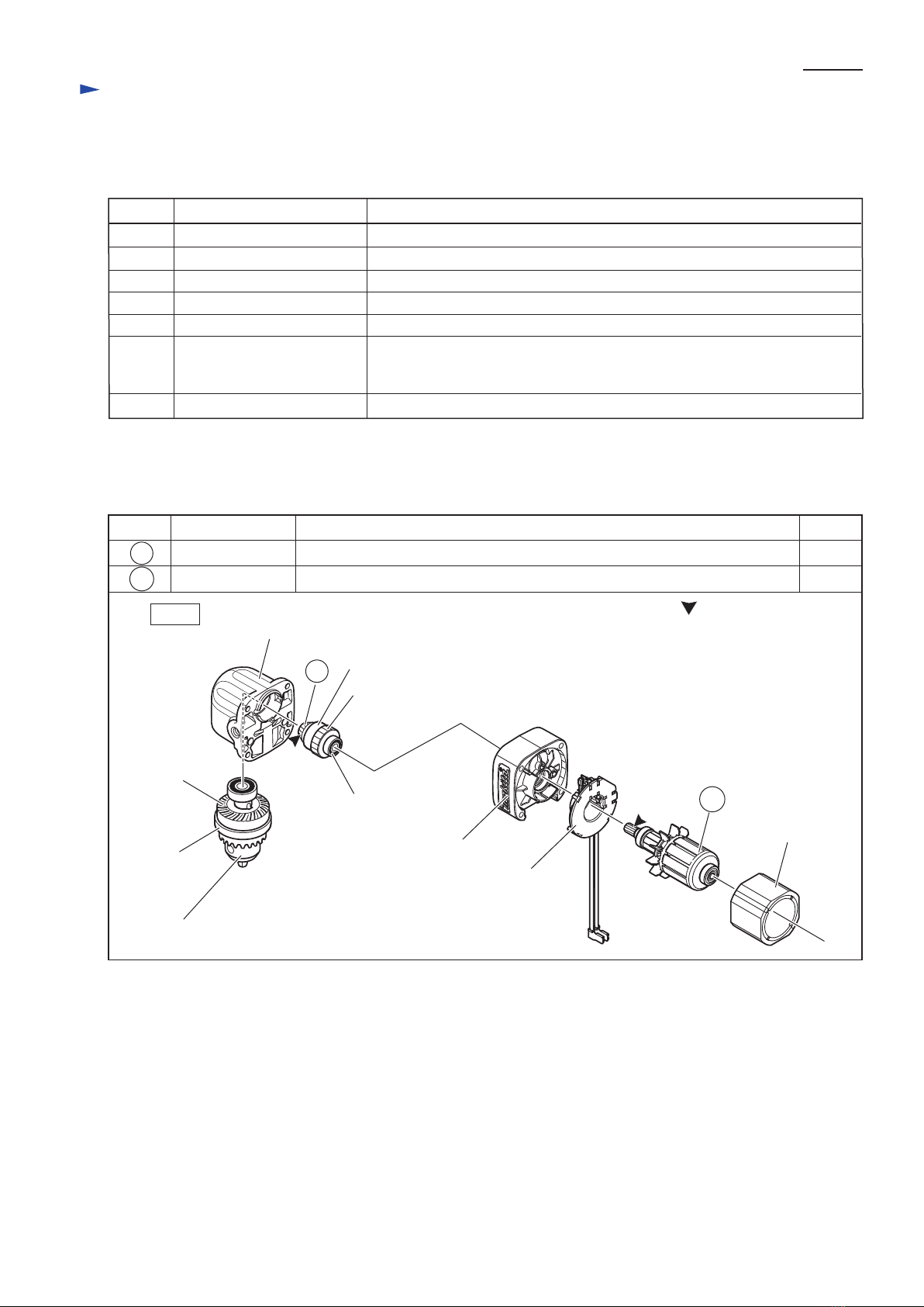
ASSEMBLING
1) If the jaws of Drill chuck are open, make them close for smooth assembling of Ball bearing 6806DDW and Spiral bevel
gear 26. Refer to Fig. 6.
2) Do not forget to assemble Key 4 to Drill chuck S10. Refer to Fig. 7.
3) Do the reverse of the disassembling steps.
Repair
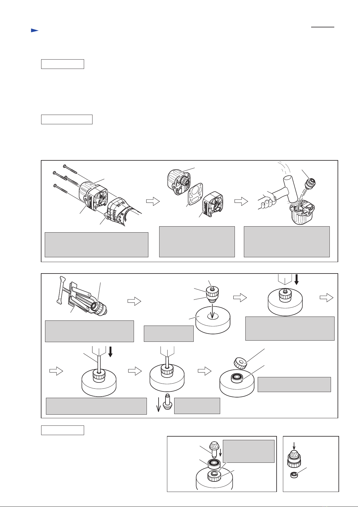
DISASSEMBLING
[3]-2. Spur Gear 29, Spiral Bevel Gear 9
1) Disassemble Bearing retainer, Drill chuck S10 from Gear housing as illustrated in Figs. 2, 3, 4.
2) Disassemble the Gear section as illustrated in Fig. 8.
3) The Gear section is disassembled as illustrated in Fig. 9.
Disassemble Gear housing together with
Gear housing cover from Motor housing
by unscrewing 4x45 Tapping screw.
Remove Gear housing cover
from Gear housing by pulling
off. Pay attention not to lose
Gasket in this step.
Strike the edge of Gear housing
with plastic hammer.
Now Gear section can be removed
from Gear housing.
4x45 Tapping screw (4pcs.)
Gear housing
Gasket
Motor housing
Gear housing cover
Gear housing
Gear housing
cover
Gear section
Fig. 8
Fig. 9
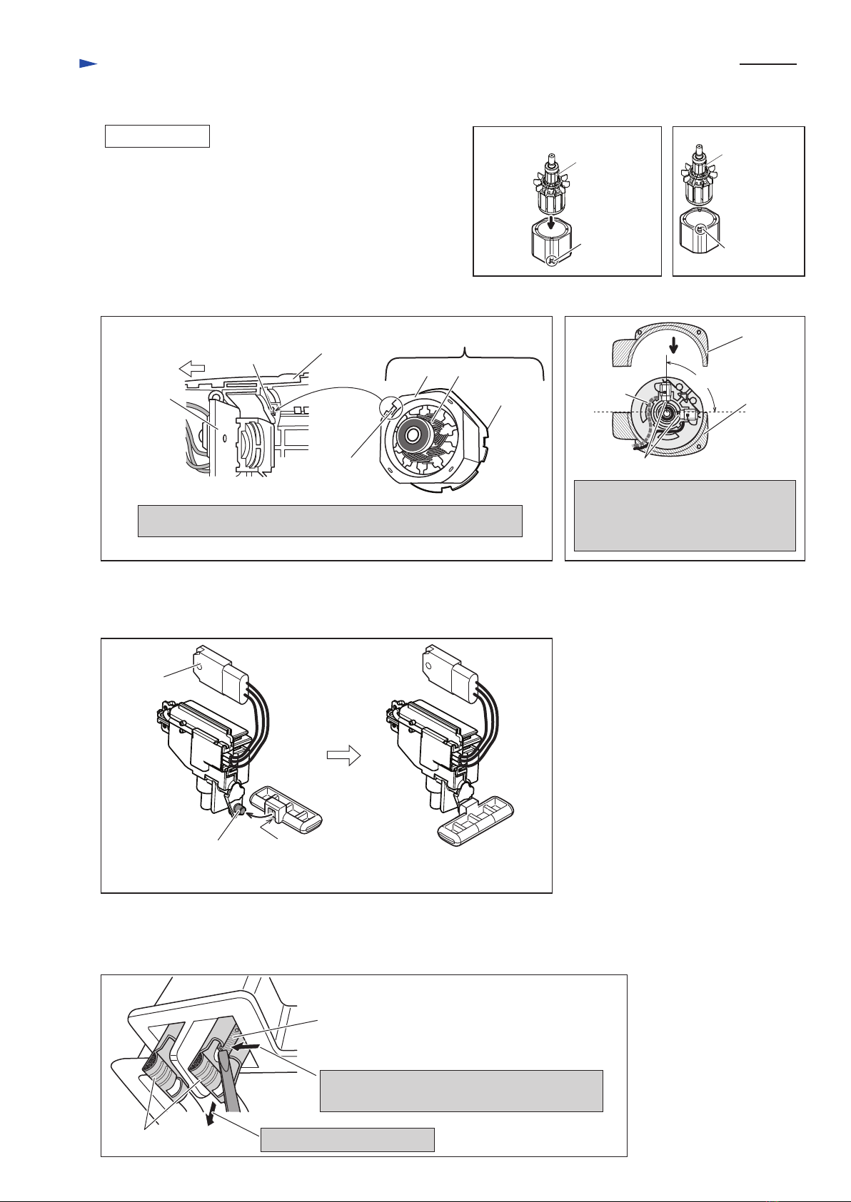
ASSEMBLING
1R269
1R280
1R036
Disassemble Ball bearing 696ZZ
from the shaft of Spiral bevel gear 9
with 1R269.
Ball bearing
608ZZ
Accept Ball bearing
608ZZ with 1R036.
Push Shaft end of Spiral bevel gear 9
to ths surface of Spur gear 29 with
arbor press.
Spiral bevel gear 9
is removed.
Spur gear 29 and Ball bearing
608ZZ are separated.
Applying 1R280 to the shaft end of
Spiral bevel gear 9, press with arbor press.
Spur gear 29
shaft end of Spiral bevel gear 9
Ball bearing 608ZZ
Spur gear 29
Ball bearing 696ZZ
(1) Assemble Ball bearing 608ZZ and Spur gear 29
to Spiral bevel gear 9. (Fig. 10)
(2) Assemble Ball bearing 696ZZ to the shaft end
of Spiral bevel gear 9. (Fig. 11)
(3) Do the reverse of the disassembling steps.
Refer to Fig. 8.
Spur gear 29
< Note >
Rib has to face
Ball bearing 608ZZ.
Ball bearing
608ZZ Ball bearing
696ZZ
Spiral bevel
gear 9
Fig. 10 Fig. 11