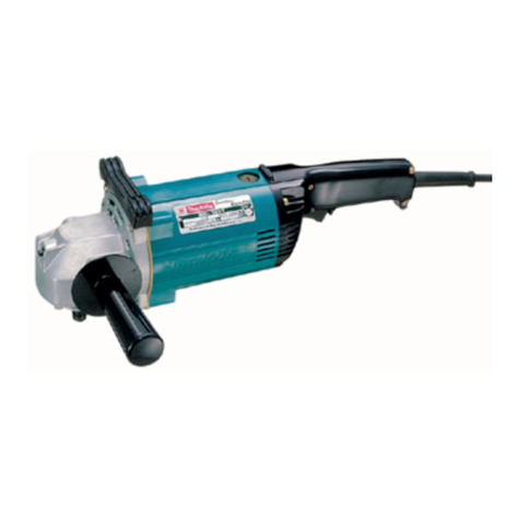
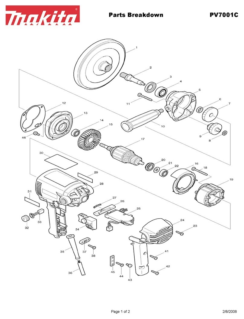
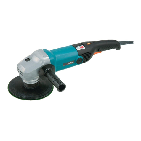
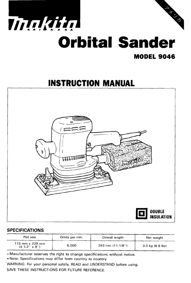
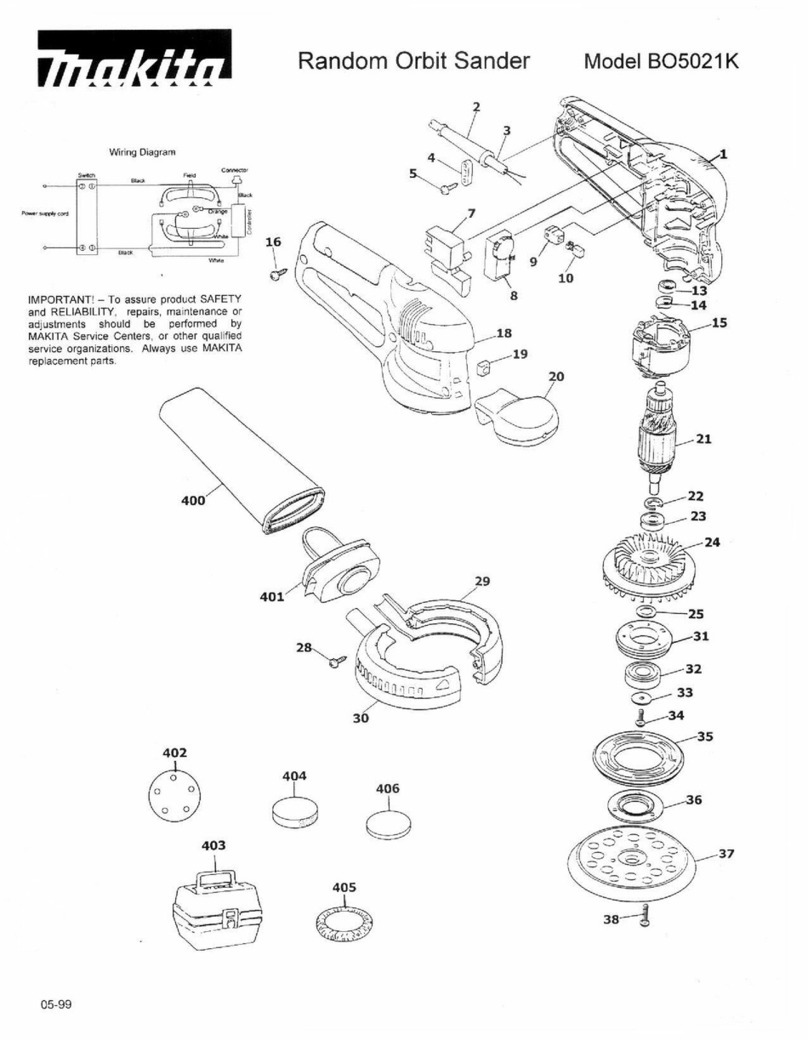
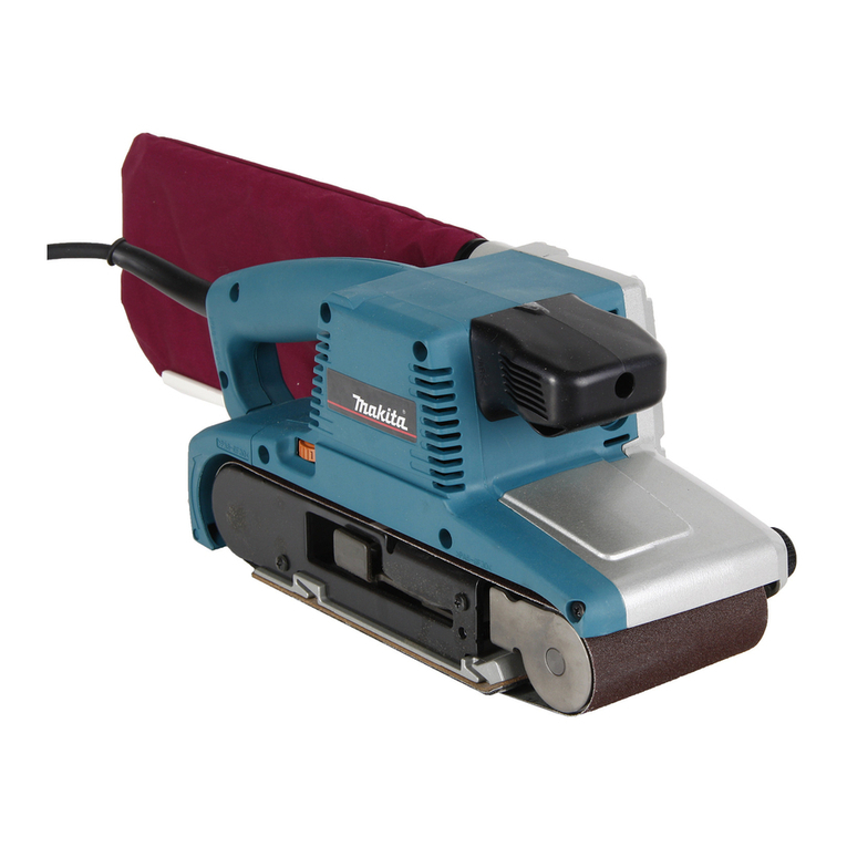
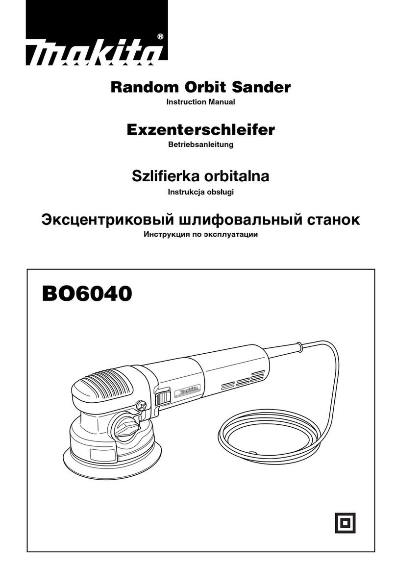
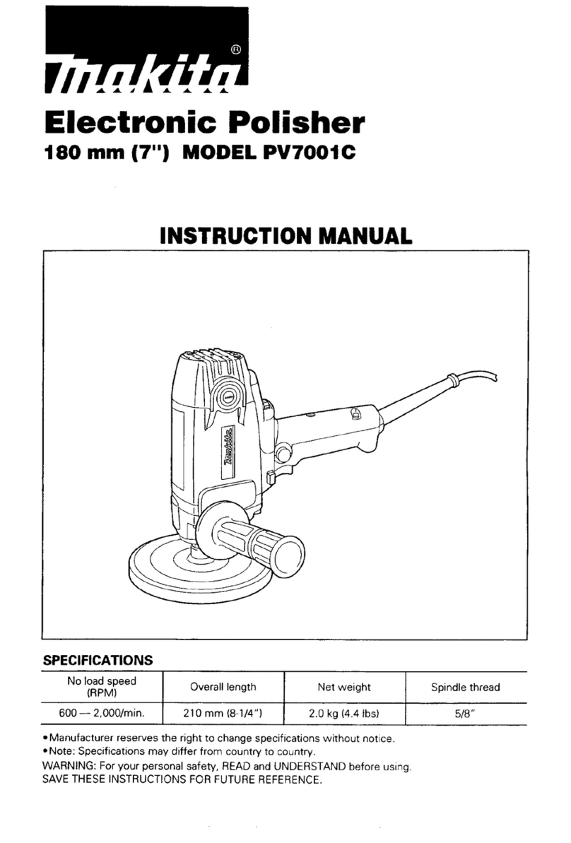
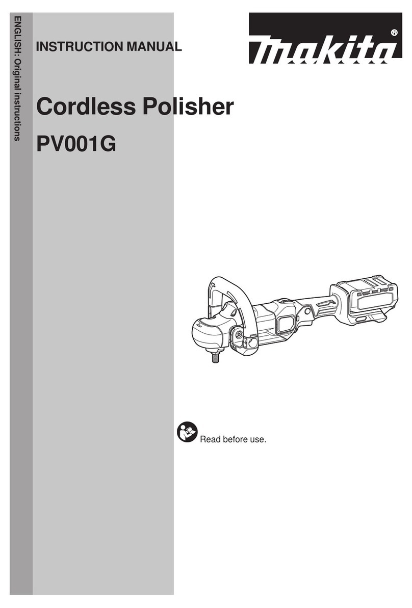
Makita PV7001 User manual

INSTRUCTION MANUAL
WARNING:
For your personal safety, READ and UNDERSTAND before using.
SAVE THESE INSTRUCTIONS FOR FUTURE REFERENCE.
ENGLISH
Polisher
Electronic Polisher
MODEL PV7001
MODEL PV7001C
004418

2
SPECIFICATIONS
• Due to our continuing programme of research and development, the specifications herein are subject to change
without notice.
• Note: Specifications may differ from country to country.
Symbols END101-1
The following show the symbols used for the tool. Be
sure that you understand their meaning before use.
...................Read instruction manual.
.....................Wear safety glasses.
Intended use
The tool is intended for polishing, smoothing before
painting, finishing surfaces, and removing rust and paint.
Power supply
The tool should be connected only to a power supply of
the same voltage as indicated on the nameplate, and
can only be operated on single-phase AC supply. This
tool should be grounded while in use to protect the oper-
ator from electric shock. Use only three-wire extension
cords which have three-prong grounding-type plugs and
three-pole receptacles which accept the tool’s plug.
Model PV7001 PV7001C
Max capacities
Sponge pad/ Wool bonnet 180 mm 180 mm
Abrasive disc 180 mm 180 mm
No load speed (min-1)1,700 600 - 2,000
Overall length 210 mm 210 mm
Net weight 2.0 kg 2.0 kg

3
SAFETY INSTRUCTIONS ENA001-2
WARNING:
When using electric tools, basic safety precautions, including the following,
should always be followed to reduce the risk of fire, electric shock and
personal injury. Read all these instructions before operating this product
and save these instructions.
For safe operations:
1. Keep work area clean.
Cluttered areas and benches invite injuries.
2. Consider work area environment.
Do not expose power tools to rain. Do not use
power tools in damp or wet locations. Keep work
area well lit. Do not use power tools where there is
risk to cause fire or explosion.
3. Guard against electric shock.
Avoid body contact with earthed or grounded sur-
faces (e.g. pipes, radiators, ranges, refrigerators).
4. Keep children away.
Do not let visitors touch the tool or extension cord.
All visitors should be kept away from work area.
5. Store idle tools.
When not in use, tools should be stored in a dry,
high or locked up place, out of reach of children.
6. Do not force the tool.
It will do the job better and safer at the rate for which
it was intended.
7. Use the right tool.
Do not force small tools or attachments to do the job
of a heavy duty tool. Do not use tools for purposes
not intended; for example, do not use circular saws
to cut tree limbs or logs.
8. Dress properly.
Do not wear loose clothing or jewellery, they can be
caught in moving parts. Rubber gloves and non-skid
footwear are recommended when working outdoors.
Wear protecting hair covering to contain long hair.
9. Use safety glasses and hearing protection.
Also use face or dust mask if the cutting operation is
dusty.
10. Connect dust extraction equipment.
If devices are provided for the connection of dust
extraction and collection facilities ensure these are
connected and properly used.
11. Do not abuse the cord.
Never carry the tool by the cord or yank it to discon-
nect it from the socket. Keep the cord away from
heat, oil and sharp edges.
12. Secure work.
Use clamps or a vice to hold the work. It is safer
than using your hand and it frees both hands to
operate the tool.
13. Do not overreach.
Keep proper footing and balance at all times.
14. Maintain tools with care.
Keep cutting tools sharp and clean for better and
safer performance. Follow instructions for lubrica-
tion and changing accessories. Inspect tool cord
periodically and if damaged have it repaired by an
authorized service facility. Inspect extension cords
periodically and replace, if damaged. Keep handles
dry, clean and free from oil and grease.
15. Disconnect tools.
When not in use, before servicing and when chang-
ing accessories such as blades, bits and cutters.
16. Remove adjusting keys and wrenches.
Form the habit of checking to see that keys and
adjusting wrenches are removed from the tool
before turning it on.
17. Avoid unintentional starting.
Do not carry a plugged-in tool with a finger on the
switch. Ensure switch is off when plugging in.
18. Use outdoor extension leads.
When tool is used outdoors, use only extension
cords intended for outdoor use.
19. Stay alert.
Watch what you are doing. Use common sense. Do
not operate tool when you are tired.
20. Check damaged parts.
Before further use of the tool, a guard or other part
that is damaged should be carefully checked to
determine that it will operate properly and perform
its intended function. Check for alignment of moving
parts, free running of moving parts, breakage of
parts, mounting and any other conditions that may
affect its operation. A guard or other part that is
damaged should be properly repaired or replaced
by an authorized service center unless otherwise
indicated in this instruction manual. Have defective
switches replaced by an authorized service facility.
Do not use the tool if the switch does not turn it on
and off.
21. Warning.
The use of any accessory or attachment, other than
those recommended in this instruction manual or
the catalog, may present a risk of personal injury.
22. Have your tool repaired by a qualified person.
This electric tool is in accordance with the relevant
safety requirements. Repairs should only be carried
out by qualified persons using original spare parts,
otherwise this may result in considerable danger to
the user.

4
ADDITIONAL SAFETY RULES ENB072-1
1. Always use eye and ear protection. Other per-
sonal protective equipment such as dust mask,
gloves, helmet and apron should be worn.
2. Always be sure that the tool is switched off and
unplugged before carrying out any work on the
tool.
3. Accessories must be rated for at least the speed
recommended on the tool warning label. Wheels
and other accessories running over rated speed can
fly apart and cause injury.
4. Check the backing pad carefully for cracks,
damage or deformity before operation. Replace
cracked, damaged or deformed pad immedi-
ately.
5. Check that the workpiece is properly supported.
6. Hold the tool firmly.
7. Keep hands away from rotating parts.
8. Make sure the abrasive disc or wool bonnet is
not contacting the workpiece before the switch
is turned on.
9. When sanding metal surfaces, watch out for fly-
ing sparks. Hold the tool so that sparks fly away
from you and other persons or flammable mate-
rials.
10. Do not leave the tool running. Operate the tool
only when hand-held.
11. Pay attention that the wheel continues to rotate
after the tool is switched off.
12. Do not touch the workpiece immediately after
operation; it may be extremely hot and could
burn your skin.
13. If working place is extremely hot and humid, or
badly polluted by conductive dust, use a short-
circuit breaker (30 mA) to assure operator
safety.
14. Do not use the tool on any materials containing
asbestos.
15. Do not use water or grinding lubricant.
16. Ventilate your work area adequately when you
perform sanding operations.
17. Some material contains chemicals which may
be toxic. Take caution to prevent dust inhalation
and skin contact. Follow material supplier safety
data.
18. Always use the correct dust mask/respirator for
the material and application you are working
with when sanding.
19. Ensure that ventilation openings are kept clear
when working in dusty conditions. If it should
become necessary to clear dust, first discon-
nect the tool from the mains supply ( use non
metallic objects ) and avoid damaging internal
parts.
20. PROPER GROUNDING. This tool should be
grounding while in use to protect the operator
from electric shock.
21. EXTENSION CORDS. Use only three-wire exten-
sion cords which have three-prong grounding-
type plugs and three-pole receptacles which
accept the tool’s plug. Replace or repair dam-
aged or worn cord immediately.
SAVE THESE INSTRUCTIONS

5
FUNCTIONAL
DESCRIPTION CAUTION:
• Always be sure that the tool is switched off and unplugged before
adjusting or checking function on the tool.
Switch action
CAUTION:
• Before plugging in the tool, always check to see that the switch trigger
actuates properly and returns to the “OFF” position when released.
To start the tool, simply pull the switch trigger. Release the switch trigger to
stop.
For continuous operation, pull the switch trigger and then push in the lock but-
ton.
To stop the tool from the locked position, pull the switch trigger fully, then
release it.
Speed adjusting dial
For PV7001C only
The tool speed can be changed by turning the speed adjusting dial to a given
number setting from 1 to 5.
Higher speed is obtained when the dial is turned in the direction of number 5.
And lower speed is obtained when it is turned in the direction of number 1.
Refer to the table for the relationship between the number settings on the dial
and the approximate tool speed.
C00040
CAUTION:
• If the tool is operated continuously at low speeds for a long time, the
motor will get overloaded, resulting in tool malfunction.
• The speed adjusting dial can be turned only as far as 5 and back to 1. Do
not force it past 5 or 1, or the speed adjusting function may no longer
work.
The tools equipped with electronic function are easy to operate because of the
following features.
•Electronic constant speed control
Possible to get fine finish, because the rotating speed is kept constant
even under the loaded condition.
•Soft start feature
Soft start because of suppressed starting shock.
1. Switch trigger
2. Lock button
1
2
003407
1. Speed adjusting dial
2
1
003408
Number min-1 (RPM)
1 - 2 600 - 800
2 - 3 800 - 1,300
3 - 4 1,300 - 1,800
4 - 5 1,800 - 2,000

6
High-Low speed setting button
For PV7001C only
The tool speed can be changed instantly while the tool is running. Depress the
“I”position for lowest speed and depress “II”position for a given number set-
ting.
The tool speed cannot be changed when the button is in “I”position, even if
you turn the speed adjusting dial. When you turn the speed adjusting dial,
always be sure that the button is depressed in “II”position.
ASSEMBLY CAUTION:
•Always be sure that the tool is switched off and unplugged before
carrying out any work on the tool.
Installing side grip (auxiliary handle) & cover
CAUTION:
•Always be sure that the side grip is installed securely before operation.
Install the cover, then screw the side grip on the tool securely. The side grip
and the cover can be installed on either side of the tool.
1. High-Low speed setting button
1
003444
1. Cover
2. Side grip
1. Cover
2. Side grip
1
2
004419
1
2
004420

7
Installing or removing backing pad
Hold the spindle with the wrench so that it cannot revolve. Then screw the pad
onto the spindle all the way. (The pad can be used to install the optional
sponge pad.)
To remove the pad, follow the installation procedure in reverse.
Installing or removing sponge pad
To install the sponge pad, first remove all dirt or foreign matter from the pad.
Install the sponge pad to the pad.
To remove the pad, pull it off from the pad slowly.
Installing or removing the wool bonnet
Mount the rubber pad onto the spindle. Screw the lock nut onto the spindle.
To tighten the lock nut, hold the spindle with the wrench so that it cannot
revolve, then use the lock nut wrench and securely tighten clockwise.
1. Backing pad
2. Spindle
3. Wrench
1
2
3
004421
1. Sponge pad
2. Pad
1
2
004422
1. Wool bonnet
2. Lock nut
3. Rubber pad
1
2
3
004424
1. Lock nut wrench
2. Wrench
1
2
004425

8
Fit the wool bonnet completely over the rubber pad and pull the string tight. Tie
a bow knot and tuck the knot and any loose strings between the wool bonnet
and the rubber pad.
To remove the wool bonnet, follow the installation procedure in reverse.
Installing or removing abrasive disc
NOTE:
•Use sander accessories specified in this manual. These must be
purchased separately.
Mount the rubber pad onto the spindle. Fit the abrasive disc on the rubber pad
and screw the lock nut onto the spindle.
To tighten the lock nut, hold the spindle with the wrench so that it cannot
revolve, then use the lock nut wrench and securely tighten clockwise.
To remove the disc, follow the installation procedure in reverse.
OPERATION
Polishing operation by sponge pad
CAUTION:
•Always wear safety glasses or a face shield during operation.
In general, keep the sponge pad at an angle of about 15 degrees to the work-
piece surface.
004426
1. Lock nut
2. Abrasive disc
3. Rubber pad
4. Spindle
1
2
3
4
003414
1. Lock nut wrench
2. Wrench
1
2
004427
003479

9
Polishing operation by wool bonnet
CAUTION:
•Always wear safety glasses or a face shield during operation.
Hold the tool firmly. Turn the tool on and then apply the wool bonnet to the
workpiece.
In general, keep the wool bonnet at an angle of about 15 degrees to the work-
piece surface.
Apply slight pressure only. Excessive pressure will result in poor performance
and premature wear to wool bonnet.
Sanding operation
CAUTION:
•Always wear safety goggles or a face shield during operation.
•Never switch on the tool when it is in contact with the workpiece, it may
cause an injury to operator.
•Never run the tool without the abrasive disc. You may seriously damage
the pad.
Hold the tool firmly. Turn the tool on and then apply the abrasive disc to the
workpiece.
In general, keep the abrasive disc at an angle of about 15 degrees to the work-
piece surface.
Apply slight pressure only. Excessive pressure will result in poor performance
and premature wear to abrasive disc.
MAINTENANCE CAUTION:
•Always be sure that the tool is switched off and unplugged before
attempting to perform inspection or maintenance.
Replacing carbon brushes
Remove and check the carbon brushes regularly. Replace when they wear
down to the limit mark. Keep the carbon brushes clean and free to slip in the
holders. Both carbon brushes should be replaced at the same time. Use only
identical carbon brushes.
Use a screwdriver to remove the brush holder caps. Take out the worn carbon
brushes, insert the new ones and secure the brush holder caps.
To maintain product SAFETY and RELIABILITY, repairs, any other mainte-
nance or adjustment should be performed by Makita Authorized Service Cent-
ers, always using Makita replacement parts.
15
003480
15
003421
1. Limit mark
1
001145
1. Brush holder cap
2. Screwdriver
2
1
003423

10
ACCESSORIES
CAUTION:
•These accessories or attachments are recommended for use with your Makita tool specified in this manual. The
use of any other accessories or attachments might present a risk of injury to persons. Only use accessory or
attachment for its stated purpose.
If you need any assistance for more details regarding these accessories, ask your local Makita service center.
•Sponge pad (Hook & loop)
•Backing pad 165 (Hook & loop)
•Abrasive discs
•Wool bonnet 180
•Rubber pad 170
•Lock nut 48
•Lock nut wrench 28
•Wrench 17
•Side grip (auxiliary handle)

Memo
11

Makita Corporation
884355D9
Other manuals for PV7001
1
This manual suits for next models
1
Table of contents
Other Makita Sander manuals

Makita
Makita PW5000C User manual

Makita
Makita 9403 User manual

Makita
Makita BO6050 User manual

Makita
Makita BO5030 User manual

Makita
Makita 9741 User manual

Makita
Makita GV7000 User manual

Makita
Makita BO4530 User manual

Makita
Makita 9207SPB User manual

Makita
Makita BO5012 User manual

Makita
Makita DPV300 User manual

Makita
Makita 9031 User manual

Makita
Makita DBO180 User manual

Makita
Makita 9741 User manual

Makita
Makita DBO480 User manual

Makita
Makita 9031 User manual

Makita
Makita DBS180 User manual

Makita
Makita 9902 User manual

Makita
Makita M9203 User manual

Makita
Makita BO6030 User manual

Makita
Makita M9200 User manual