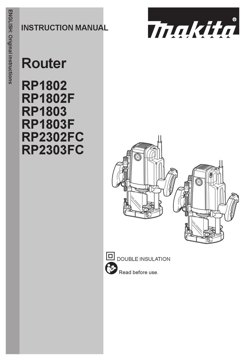
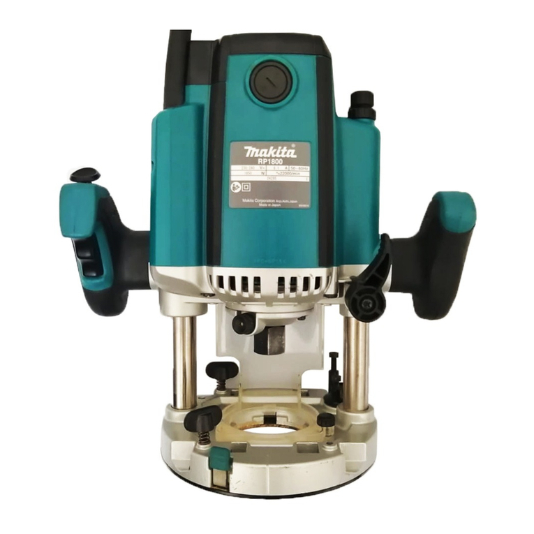
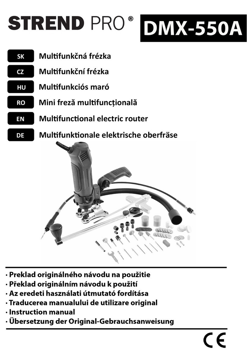
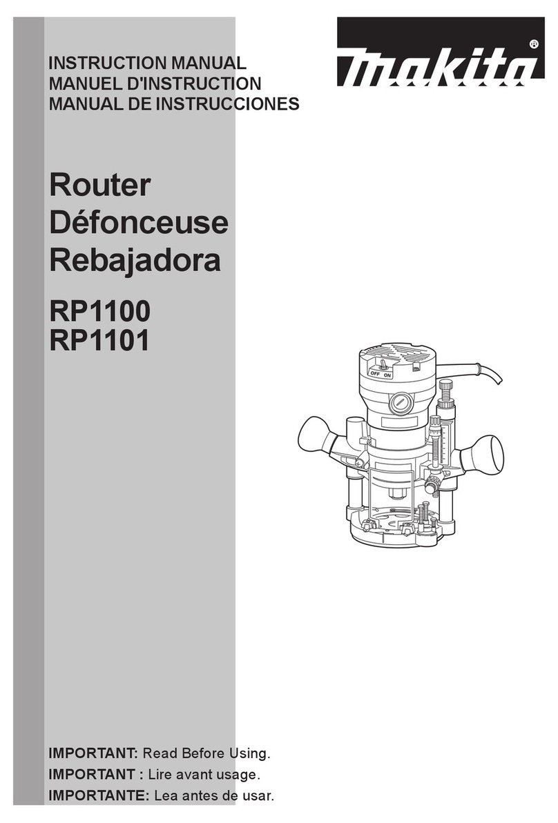
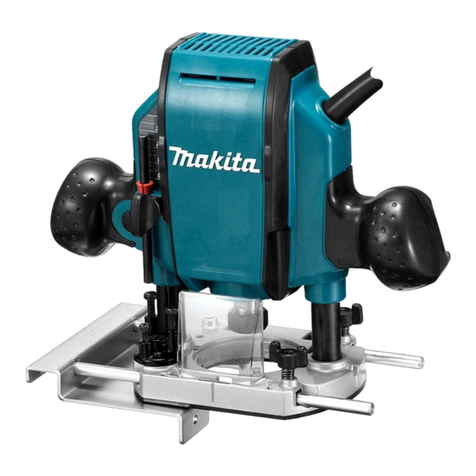
Makita RP1802 User manual

RP1802
RP1802F
RP1803
RP1803F
RP2302FC
RP2303FC
EN Router INSTRUCTION MANUAL 9
SV Handöverfräs BRUKSANVISNING 17
NO Håndoverfres BRUKSANVISNING 25
FI Yläjyrsin KÄYTTÖOHJE 33
DA Overfræser BRUGSANVISNING 41
LV Frēzmašīna LIETOŠANAS INSTRUKCIJA 49
LT Freza NAUDOJIMO INSTRUKCIJA 57
ET Proilfrees KASUTUSJUHEND 65
RU Фрезер РУКОВОДСТВО ПО
ЭКСПЛУАТАЦИИ 73

2
4
7
8
15
6
2
3
Fig.1
1
Fig.2
1
2
3
Fig.3
1
2
Fig.4
1
Fig.5
1
Fig.6
1
Fig.7
1
2
3
4
Fig.8

3
1
Fig.9
Fig.10
1
2
3
44
2
Fig.11
1
23
4
Fig.12
1
2
3
4
5
Fig.13
C1
A
B
2
Fig.14
Fig.15
1
2
3
Fig.16

4
1
2
3
Fig.17
1
Fig.18
Fig.19
Fig.20
Fig.21
1
2
Fig.22
1
2
3
5
6
4
(X)
Fig.23
1
Fig.24

5
1
2
3
45
6
Fig.25
3
1
2
Fig.26
1
2
Fig.27
Fig.28
2
1
Fig.29
1
Fig.30
1
2
Fig.31
1
Fig.32

6
1
Fig.33
1
Fig.34
Fig.35
R
Fig.36
Fig.37
Fig.38
Fig.39
Fig.40

7
Fig.41
Fig.42
Fig.43
Fig.44
Fig.45
Fig.46
Fig.47
Fig.48

8
Fig.49

9ENGLISH
ENGLISH (Original instructions)
SPECIFICATIONS
Model: RP1802
RP1802F
RP1803
RP1803F
RP2302FC RP2303FC
Collet chuck capacity 12 mm or 1/2″
Plunge capacity 0 - 70 mm
No load speed 23,000 min-1 22,000 min-1 9,000 - 23,000 min-1
Overall height 312 mm 327 mm
Net weight 6.2 kg
Safety class /II
Lamp --
Speed adjusting dial -
Electric brake - -
•
Due to our continuing program of research and development, the specications herein are subject to change without notice.
• Specications may dier from country to country.
• Weight according to EPTA-Procedure 01/2014
Intended use
The tool is intended for ush trimming and proling of
wood, plastic and similar materials.
Power supply
The tool should be connected only to a power supply of the same
voltage as indicated on the nameplate, and can only be operated
on single-phase AC supply. They are double-insulated and can,
therefore, also be used from sockets without earth wire.
Noise
The typical A-weighted noise level determined accord-
ing to EN62841-2-17:
Model RP1802
Sound pressure level (LpA) : 85 dB(A)
Sound power level (LWA) : 96 dB (A)
Uncertainty (K) : 3 dB(A)
Model RP1802F
Sound pressure level (LpA) : 85 dB(A)
Sound power level (LWA) : 96 dB (A)
Uncertainty (K) : 3 dB(A)
Model RP1803
Sound pressure level (LpA) : 85 dB(A)
Sound power level (LWA) : 96 dB (A)
Uncertainty (K) : 3 dB(A)
Model RP1803F
Sound pressure level (LpA) : 85 dB(A)
Sound power level (LWA) : 96 dB (A)
Uncertainty (K) : 3 dB(A)
Model RP2302FC
Sound pressure level (LpA) : 88 dB(A)
Sound power level (LWA) : 99 dB (A)
Uncertainty (K) : 3 dB(A)
Model RP2303FC
Sound pressure level (LpA) : 88 dB(A)
Sound power level (LWA) : 99 dB (A)
Uncertainty (K) : 3 dB(A)
NOTE: The declared noise emission value(s) has
been measured in accordance with a standard test
method and may be used for comparing one tool with
another.
NOTE: The declared noise emission value(s)
may also be used in a preliminary assessment of
exposure.
WARNING: Wear ear protection.
WARNING: The noise emission during actual
use of the power tool can dier from the declared
value(s) depending on the ways in which the
tool is used especially what kind of workpiece is
processed.
WARNING: Be sure to identify safety mea-
sures to protect the operator that are based on an
estimation of exposure in the actual conditions of
use (taking account of all parts of the operating
cycle such as the times when the tool is switched
o and when it is running idle in addition to the
trigger time).
Vibration
The vibration total value (tri-axial vector sum) deter-
mined according to EN62841-2-17:
Model RP1802
Work mode: cutting grooves in MDF
Vibration emission (ah) : 5.1 m/s2
Uncertainty (K) : 1.5 m/s2
Model RP1802F
Work mode: cutting grooves in MDF
Vibration emission (ah) : 5.1 m/s2
Uncertainty (K) : 1.5 m/s2
Model RP1803
Work mode: cutting grooves in MDF
Vibration emission (ah) : 5.1 m/s2
Uncertainty (K) : 1.5 m/s2

10 ENGLISH
Model RP1803F
Work mode: cutting grooves in MDF
Vibration emission (ah) : 5.1 m/s2
Uncertainty (K) : 1.5 m/s2
Model RP2302FC
Work mode: cutting grooves in MDF
Vibration emission (ah) : 4.2 m/s2
Uncertainty (K) : 1.5 m/s2
Model RP2303FC
Work mode: cutting grooves in MDF
Vibration emission (ah) : 4.2 m/s2
Uncertainty (K) : 1.5 m/s2
NOTE: The declared vibration total value(s) has been
measured in accordance with a standard test method
and may be used for comparing one tool with another.
NOTE: The declared vibration total value(s) may also
be used in a preliminary assessment of exposure.
WARNING: The vibration emission during
actual use of the power tool can dier from the
declared value(s) depending on the ways in which
the tool is used especially what kind of workpiece
is processed.
WARNING: Be sure to identify safety mea-
sures to protect the operator that are based on an
estimation of exposure in the actual conditions of
use (taking account of all parts of the operating
cycle such as the times when the tool is switched
o and when it is running idle in addition to the
trigger time).
EC Declaration of Conformity
For European countries only
The EC declaration of conformity is included as Annex A
to this instruction manual.
SAFETY WARNINGS
General power tool safety warnings
WARNING: Read all safety warnings, instruc-
tions, illustrations and specications provided
with this power tool. Failure to follow all instructions
listed below may result in electric shock, re and/or
serious injury.
Save all warnings and instruc-
tions for future reference.
The term "power tool" in the warnings refers to your
mains-operated (corded) power tool or battery-operated
(cordless) power tool.
Router safety warnings
1. Hold the power tool by insulated gripping
surfaces only, because the cutter may contact
its own cord. Cutting a "live" wire may make
exposed metal parts of the power tool "live" and
could give the operator an electric shock.
2. Use clamps or another practical way to secure
and support the workpiece to a stable plat-
form. Holding the work by your hand or against
the body leaves it unstable and may lead to loss of
control.
3. The cutter bit shank must match the designed
collet chuck.
4. Only use a bit that is rated at least equal to the
maximum speed marked on the tool.
5. Wear hearing protection during extended
period of operation.
6. Handle the router bits very carefully.
7. Check the router bit carefully for cracks or
damage before operation. Replace cracked or
damaged bit immediately.
8. Avoid cutting nails. Inspect for and remove all
nails from the workpiece before operation.
9. Hold the tool rmly with both hands.
10. Keep hands away from rotating parts.
11. Make sure the router bit is not contacting the
workpiece before the switch is turned on.
12. Before using the tool on an actual workpiece,
let it run for a while. Watch for vibration or
wobbling that could indicate improperly
installed bit.
13. Be careful of the router bit rotating direction
and the feed direction.
14. Do not leave the tool running. Operate the tool
only when hand-held.
15. Always switch o and wait for the router bit to
come to a complete stop before removing the
tool from workpiece.
16. Do not touch the router bit immediately after
operation; it may be extremely hot and could
burn your skin.
17. Do not smear the tool base carelessly with
thinner, gasoline, oil or the like. They may
cause cracks in the tool base.
18. Some material contains chemicals which may
be toxic. Take caution to prevent dust inhala-
tion and skin contact. Follow material supplier
safety data.
19. Always use the correct dust mask/respirator
for the material and application you are work-
ing with.
20. Place the tool on stable area. Otherwise falling
accident may occur and cause an injury.
21. Keep cord away from your foot or any objects.
Otherwise an entangled cord may cause a falling
accident and result in personal injury.
SAVE THESE INSTRUCTIONS.
WARNING: DO NOT let comfort or familiarity
with product (gained from repeated use) replace
strict adherence to safety rules for the subject
product. MISUSE or failure to follow the safety
rules stated in this instruction manual may cause
serious personal injury.
11 ENGLISH
FUNCTIONAL
DESCRIPTION
CAUTION: Always be sure that the tool is
switched o and unplugged before adjusting or
checking function on the tool.
Adjusting the depth of cut
► Fig.1: 1. Lock lever 2. Adjusting hex bolt 3. Stopper
block 4. Adjusting knob 5. Depth pointer
6. Stopper pole 7. Stopper pole setting nut
8. Fast-feed button
1.
Place the tool on a at surface. Loosen the lock lever
and lower the tool body until the router bit just touches the
at surface. Tighten the lock lever to lock the tool body.
2. Turn the stopper pole setting nut counterclock-
wise. Lower the stopper pole until it makes contact
with the adjusting hex bolt. Align the depth pointer with
the "0" graduation. The depth of cut is indicated on the
scale by the depth pointer.
3. While pressing the fast-feed button, raise the
stopper pole until the desired depth of cut is obtained.
Minute depth adjustments can be obtained by turning
the adjusting knob (1 mm per turn).
4. By turning the stopper pole setting nut clockwise,
you can fasten the stopper pole rmly.
5. Now, your predetermined depth of cut can be
obtained by loosening the lock lever and then lowering
the tool body until the stopper pole makes contact with
the adjusting hex bolt of the stopper block.
Nylon nut
CAUTION: Do not lower the nylon nut too low.
The router bit will protrude dangerously.
The upper limit of the tool body can be adjusted by
turning the nylon nut.
► Fig.2: 1. Nylon nut
Stopper block
CAUTION: Since excessive cutting may cause
overload of the motor or diculty in controlling
the tool, the depth of cut should not be more than
15 mm at a pass when cutting grooves with an 8
mm diameter bit.
CAUTION: When cutting grooves with a 20
mm diameter bit, the depth of cut should not be
more than 5 mm at a pass.
CAUTION: For extra-deep grooving opera-
tions, make two or three passes with progres-
sively deeper bit settings.
As the stopper block has three adjusting hex bolts
which raise or lower 0.8 mm per turn, you can easily
obtain three dierent depths of cut without readjusting
the stopper pole.
► Fig.3: 1. Stopper pole 2. Adjusting hex bolt
3. Stopper block
Adjust the lowest adjusting hex bolt to obtain the deep-
est depth of cut, following the method of "Adjusting the
depth of cut".
Adjust the two remaining adjusting hex bolts to obtain
shallower depths of cut. The dierences in height of
these adjusting hex bolts are equal to the dierences in
depths of cut.
To adjust the adjusting hex bolts, turn the adjusting hex
bolts with a screwdriver or wrench. The stopper block is
also convenient for making three passes with progres-
sively deeper bit settings when cutting deep grooves.
Switch action
CAUTION: Before plugging in the tool, always
check to see that the switch trigger actuates
properly and returns to the "OFF" position when
released.
CAUTION: Make sure that the shaft lock is
released before the switch is turned on.
To prevent the switch trigger from being accidentally
pulled, a lock button is provided.
► Fig.4: 1. Lock button 2. Switch trigger
To start the tool, depress the lock button and pull the
switch trigger. Release the switch trigger to stop.
For continuous operation, depress the lock button fur-
ther while the switch trigger is being pulled.
To stop the tool, pull the switch trigger so that the lock
button returns automatically. Then release the switch
trigger.
After releasing the switch trigger, the lock-o function
works to prevent the switch trigger from being pulled.
CAUTION: Hold the tool rmly when turning
o the tool, to overcome the reaction.
Electronic function
The tool is equipped with the electronic functions for
easy operation.
Indication lamp
► Fig.5: 1. Indication lamp
The indication lamp lights up green when the tool is
plugged. If the indication lamp does not light up, the
mains cord or the controller may be defective. The indi-
cation lamp is lit but the tool does not start even if the
tool is switched on, the carbon brushes may be worn
out, or the controller, the motor or the ON/OFF switch
may be defective.
Unintentional restart proof
The tool does not start with the switch trigger pulled
even when the tool is plugged.
At this time, the indication lamp blinks in red and shows
the unintentional restart proof device is on function.
To cancel the unintentional restart proof, release the
switch trigger.
Soft start feature
Soft-start feature minimizes start-up shock, and makes
the tool start smoothly.

12 ENGLISH
Constant speed control
Only for model RP2302FC, RP2303FC
Possible to get ne nish, because the rotating speed is
kept constant even under the loaded condition.
Speed adjusting dial
Only for model RP2302FC, RP2303FC
WARNING: Do not use the speed adjusting
dial during operation. The router bit can be touched
by the operator because of reaction force. This may
result in personal injury.
NOTICE: If the tool is operated continuously
at low speeds for a long time, the motor will get
overloaded, resulting in tool malfunction.
NOTICE: The speed adjusting dial can be turned
only as far as 6 and back to 1. Do not force it past
6 or 1, or the speed adjusting function may no
longer work.
The tool speed can be changed by turning the speed
adjusting dial to a given number setting from 1 to 6.
► Fig.6: 1. Speed adjusting dial
Higher speed is obtained when the dial is turned in the
direction of number 6. And lower speed is obtained
when it is turned in the direction of number 1.
This allows the ideal speed to be selected for optimum
material processing, i.e. the speed can be correctly
adjusted to suit the material and bit diameter.
Refer to the table for the relationship between the num-
ber settings on the dial and the approximate tool speed.
Number min-1
19,000
211,000
314,000
417,000
520,000
623,000
Lighting up the lamps
Only for model RP1802F, RP1803F, RP2302FC,
RP2303FC
CAUTION: Do not look in the light or see the
source of light directly.
Pull the switch trigger to turn on the light. The lamp
keeps on lighting while the switch trigger is being pulled.
The lamp turns o approximately 10 seconds after
releasing the trigger.
► Fig.7: 1. Lamp
NOTE: Use a dry cloth to wipe the dirt o the lens of
the lamp. Be careful not to scratch the lens of lamp, or
it may lower the illumination.
ASSEMBLY
CAUTION: Always be sure that the tool is
switched o and unplugged before carrying out
any work on the tool.
Installing or removing the router bit
CAUTION: Install the router bit securely.
Always use only the wrench provided with the
tool. A loose or overtightened router bit can be
dangerous.
NOTICE: Do not tighten the collet nut without
inserting a router bit or install small shank bits
without using a collet sleeve. Either can lead to
breakage of the collet cone.
1. Insert the router bit all the way into the collet cone.
2.
Press the shaft lock to keep the shaft stationary and use
the wrench to tighten the collet nut securely. When using router
bits with smaller shank diameter, rst insert the appropriate
collet sleeve into the collet cone, then install the router bit.
► Fig.8: 1. Shaft lock 2. Wrench 3. Loosen 4. Tighten
To remove the router bit, follow the installation proce-
dure in reverse.
OPERATION
WARNING: Before operation, always make
sure that the stopper pole is secured rmly by the
stopper pole setting nut. Otherwise the depth of
cut may change during operation and cause personal
injury.
CAUTION: Before operation, always make
sure that the tool body automatically rises to
the upper limit and the router bit does not pro-
trude from the tool base when the lock lever is
loosened.
CAUTION: Always use both grips and rmly
hold the tool by both grips during operations.
CAUTION: Before operation, always make
sure that the chip deector is installed properly.
► Fig.9: 1. Chip deector
1. Set the base on the workpiece to be cut without
the router bit making any contact.
2.
Turn the tool on and wait until the router bit attains full speed.
3. Lower the tool body and move the tool forward
over the workpiece surface, keeping the base ush and
advancing smoothly until the cutting is complete.
► Fig.10
When doing edge cutting, the workpiece surface should
be on the left side of the router bit in the feed direction.
► Fig.11: 1. Workpiece 2. Bit revolving direction
3. View from the top of the tool 4. Feed
direction

13 ENGLISH
NOTE: Moving the tool forward too fast may cause
a poor quality of cut, or damage to the router bit or
motor. Moving the tool forward too slowly may burn
and mar the cut. The proper feed rate will depend on
the router bit size, the kind of workpiece and depth
of cut.
Before beginning the cut on the actual workpiece, it
is advisable to make a sample cut on a piece of scrap
lumber. This will show exactly how the cut will look as
well as enable you to check dimensions.
NOTE: When using the straight guide or the trimmer
guide, be sure to install it on the right side in the feed
direction. This will help to keep it ush with the side of
the workpiece.
► Fig.12: 1. Feed direction 2. Bit revolving direction
3. Workpiece 4. Straight guide
Straight guide
The straight guide is eectively used for straight cuts
when chamfering or grooving.
1. Install the straight guide on the guide holder using
the clamping screw (B). Insert the guide holder into the
holes in the tool base and tighten the clamping screw
(A). To adjust the distance between the router bit and
the straight guide, loosen the clamping screw (B) and
turn the ne adjusting screw (1.5 mm per turn). At the
desired distance, tighten the clamping screw (B) to
secure the straight guide in place.
► Fig.13: 1. Clamping screw (A) 2. Straight guide
3. Guide holder 4. Fine adjusting screw
5. Clamping screw (B)
2. When cutting, move the tool with the straight guide
ush with the side of the workpiece.
Wider straight guide of desired dimensions may be
made by using the convenient holes in the guide to bolt
on extra pieces of wood.
When using a large diameter router bit, attach pieces
of wood to the straight guide which have a thickness of
more than 15 mm (5/8″) to prevent the router bit from
striking the straight guide.
► Fig.14: 1. Straight guide 2. Wood
A=55 mm (2-3/16″)
B=55 mm (2-3/16″)
C=15 mm (5/8″) or thicker
If the distance between the side of the workpiece and the
cutting position is too wide for the straight guide, or if the
side of the workpiece is not straight, the straight guide
cannot be used. In this case, rmly clamp a straight board
to the workpiece and use it as a guide against the base.
Feed the tool in the direction of the arrow.
► Fig.15
Fine adjusting straight guide
Optional accessory
Insert the two rods into the outer mounting slots of the
guide holder, and secure them by tightening the two
clamping screws (B). Make sure that the thumb screw
(A) is tightened down, insert the two rods into the base,
and tighten the clamping screws (A).
► Fig.16: 1. Clamping screw (B) 2. Thumb screw (A)
3. Clamping screw (A)
Fine adjusting function for
positioning blade in relation to
straight guide
► Fig.17: 1. Thumb screw (A) 2. Thumb screw (B)
3. Scale ring
1. Loosen the thumb screw (A).
2. Turn the thumb screw (B) to adjust position (one
turn adjusts the position by 1 mm) as necessary.
3. Tighten the thumb screw (A) until it is secured.
Scale ring can be rotated separately, so scale unit can
be aligned to zero (0).
Adjusting guide shoe width
Loosen the screws marked by the circles to alter the
width of the straight guide. After altering width, tighten
the screws until they are secured.
Guide shoe width alteration range is 280 mm to 350
mm.
► Fig.18: 1. Screw
When set to minimum opening width
► Fig.19
When set to maximum opening width
► Fig.20
Templet guide
Optional accessory
The templet guide provides a sleeve through which the
router bit passes, allowing use of the router with templet
patterns.
► Fig.21
1. Pull the lock plate lever and insert the templet
guide.
► Fig.22: 1. Templet guide 2. Lock plate lever
2. Secure the templet to the workpiece. Place the
tool on the templet and move the tool with the templet
guide sliding along the side of the templet.
► Fig.23: 1. Router bit 2. Base 3. Base plate
4. Templet 5. Workpiece 6. Templet guide
NOTE: The workpiece will be cut a slightly dierent
size from the templet. Allow for the distance (X)
between the router bit and the outside of the templet
guide. The distance (X) can be calculated by using
the following equation:
Distance (X) = (outside diameter of the templet
guide - router bit diameter) / 2

14 ENGLISH
Trimmer guide
Optional accessory
Trimming, curved cuts in veneers for furniture and the
like can be done easily with the trimmer guide. The
guide roller rides the curve and assures a ne cut.
► Fig.24: 1. Trimmer guide
Install the trimmer guide on the guide holder using the
clamping screw (D). Insert the guide holder into the holes
in the tool base and tighten the clamping screw (A). To
adjust the distance between the router bit and the trimmer
guide, loosen the clamping screw (D) and turn the ne
adjusting screw (1.5 mm per turn). When adjusting the
guide roller up or down, loosen the clamping screw (C).
After adjusting, tighten all the clamping screws securely.
► Fig.25: 1. Guide holder 2. Fine adjusting screw
3. Clamping screw (D) 4. Clamping screw
(C) 5. Guide roller 6. Clamping screw (A)
When cutting, move the tool with the guide roller riding
the side of the workpiece.
► Fig.26: 1. Router bit 2. Guide roller 3. Workpiece
Dust nozzle sets
Use the dust nozzle for dust extraction.
1. Install the dust nozzle on the tool base using the
thumb screw so that protrusion on the dust nozzle t to
the notch in the tool base.
► Fig.27: 1. Dust nozzle 2. Thumb screw
2. Connect a vacuum cleaner to the dust nozzle.
► Fig.28
How to use screw M6 x 135 for
adjusting the depth of cut
When using the tool with a router table available in the
market, using this screw allows an operator to obtain
a small amount of adjustment of the depth of cut from
above the table.
Installing the screw with washer on
the tool
Insert the screw with washer through a screw hole on
the tool base and then screw in the threaded part of the
motor bracket of the tool. At this time, apply some grease
or lubricating oil to the inside of the screw hole on the tool
base and the threaded part of the motor bracket.
► Fig.29: 1. Flat washer 6 2. Screw M6 x 135
► Fig.30: 1. Screw M6 x 135 in a screw hole
► Fig.31: 1. Screw M6 x 135 2. Threaded part of the
motor bracket
Adjusting the depth of cut
1. A small amount of depth of cut can be obtained
by turning this screw with a screwdriver from above the
table. (1.0 mm per a full turn)
2. Turning the screw clockwise makes the depth
of cut greater and turning the screw counterclockwise
makes the depth of cut smaller.
► Fig.32: 1. Screwdriver
MAINTENANCE
CAUTION: Always be sure that the tool is
switched o and unplugged before attempting to
perform inspection or maintenance.
NOTICE: Never use gasoline, benzine, thinner,
alcohol or the like. Discoloration, deformation or
cracks may result.
To maintain product SAFETY and RELIABILITY,
repairs, any other maintenance or adjustment should
be performed by Makita Authorized or Factory Service
Centers, always using Makita replacement parts.
Replacing carbon brushes
► Fig.33: 1. Limit mark
Check the carbon brushes regularly.
Replace them when they wear down to the limit mark.
Keep the carbon brushes clean and free to slip in the
holders. Both carbon brushes should be replaced at the
same time. Use only identical carbon brushes.
1.
Use a screwdriver to remove the brush holder caps.
2. Take out the worn carbon brushes, insert the new
ones and secure the brush holder caps.
► Fig.34: 1. Brush holder cap
Only for model RP1803, RP1803F, RP2303FC
After replacing brushes, plug in the tool and break in
brushes by running tool with no load for about 10 min-
utes. Then check the tool while running and electric
brake operation when releasing the switch trigger.
If electric brake is not working well, ask your local
Makita service center for repair.
OPTIONAL ACCESSORIES
CAUTION: These accessories or attachments
are recommended for use with your Makita tool
specied in this manual. The use of any other
accessories or attachments might present a risk of
injury to persons. Only use accessory or attachment
for its stated purpose.
If you need any assistance for more details regarding
these accessories, ask your local Makita Service Center.
• Straight & groove forming bits
• Edge forming bits
• Laminate trimming bits
• Straight guide
• Trimmer guide
• Guide holder
• Templet guides
• Templet guide adapter
• Lock nut
• Collet cone
• Collet sleeve
• Wrench
• Dust nozzle set

15 ENGLISH
NOTE: Some items in the list may be included in the
tool package as standard accessories. They may
dier from country to country.
Router bits
Straight bit
► Fig.35
Unit:mm
D A L1 L2
620 50 15
1/4″
12 12 60 30
1/2″
12 10 60 25
1/2″
8 8 60 25
6 8 50 18
1/4″
6 6 50 18
1/4″
“U”Grooving bit
► Fig.36
Unit:mm
D A L1 L2 R
6 6 50 18 3
“V”Grooving bit
► Fig.37
Unit:mm
D A L1 L2 θ
1/4″ 20 50 15 90°
Drill point ush trimming bit
► Fig.38
Unit:mm
D A L1 L2 L3
12 12 60 20 35
8 8 60 20 35
6 6 60 18 28
Drill point double ush trimming bit
► Fig.39
Unit:mm
D A L1 L2 L3 L4
6 6 70 40 12 14
Board-jointing bit
► Fig.40
Unit:mm
DA1 A2 L1 L2 L3
12 38 27 61 420
Corner rounding bit
► Fig.41
Unit:mm
DA1 A2 L1 L2 L3 R
625 948 13 5 8
620 845 10 4 4
Chamfering bit
► Fig.42
Unit:mm
D A L1 L2 L3 θ
623 46 11 630°
620 50 13 545°
620 49 14 260°
Cove beading bit
► Fig.43
Unit:mm
D A L1 L2 R
620 43 8 4
625 48 13 8
Ball bearing ush trimming bit
► Fig.44
Unit:mm
D A L1 L2
610 50 20
1/4″
Ball bearing corner rounding bit
► Fig.45
Unit:mm
DA1 A2 L1 L2 L3 R
615 837 73.5 3
621 840 10 3.5 6
1/4″ 21 840 10 3.5 6

16 ENGLISH
Ball bearing chamfering bit
► Fig.46
Unit:mm
DA1 A2 L1 L2 θ
626 842 12 45°
1/4″
620 841 11 60°
Ball bearing beading bit
► Fig.47
Unit:mm
DA1 A2 A3 L1 L2 L3 R
620 12 840 10 5.5 4
626 12 842 12 4.5 7
Ball bearing cove beading bit
► Fig.48
Unit:mm
DA1 A2 A3 A4 L1 L2 L3 R
620 18 12 840 10 5.5 3
626 22 12 842 12 5 5
Ball bearing roman ogee bit
► Fig.49
Unit:mm
DA1 A2 L1 L2 L3 R1 R2
620 840 10 4.5 2.5 4.5
626 842 12 4.5 3 6

17 SVENSKA
SVENSKA (Originalinstruktioner)
SPECIFIKATIONER
Modell: RP1802
RP1802F
RP1803
RP1803F
RP2302FC RP2303FC
Spännhylschuckens kapacitet 12 mm eller 1/2″
Dykkapacitet 0 - 70 mm
Hastighet utan belastning 23 000 min-1 22 000 min-1 9 000 - 23 000 min-1
Total höjd 312 mm 327 mm
Nettovikt 6,2 kg
Säkerhetsklass /II
Lampa --
Ratt för hastighetsinställning -
Elektronisk broms - -
•
På grund av vårt pågående program för forskning och utveckling kan dessa specikationer ändras utan föregående meddelande.
• Specikationer kan variera mellan olika länder.
• Vikt enligt EPTA-procedur 01/2014
Avsedd användning
Verktyget är avsett för trimning och prolering av trä,
plast och liknande material.
Strömförsörjning
Maskinen får endast anslutas till elnät med samma
spänning som anges på typplåten och med enfasig
växelström. De är dubbelisolerade och får därför också
anslutas i ojordade vägguttag.
Buller
Den normala bullernivån för A-belastning är bestämd
enligt EN62841-2-17:
Modell RP1802
Ljudtrycksnivå (LpA) : 85 dB (A)
Ljudeektnivå (LWA) : 96 dB (A)
Mättolerans (K): 3 dB (A)
Modell RP1802F
Ljudtrycksnivå (LpA) : 85 dB (A)
Ljudeektnivå (LWA) : 96 dB (A)
Mättolerans (K): 3 dB (A)
Modell RP1803
Ljudtrycksnivå (LpA) : 85 dB (A)
Ljudeektnivå (LWA) : 96 dB (A)
Mättolerans (K): 3 dB (A)
Modell RP1803F
Ljudtrycksnivå (LpA) : 85 dB (A)
Ljudeektnivå (LWA) : 96 dB (A)
Mättolerans (K): 3 dB (A)
Modell RP2302FC
Ljudtrycksnivå (LpA) : 88 dB (A)
Ljudeektnivå (LWA) : 99 dB (A)
Mättolerans (K): 3 dB (A)
Modell RP2303FC
Ljudtrycksnivå (LpA) : 88 dB (A)
Ljudeektnivå (LWA) : 99 dB (A)
Mättolerans (K): 3 dB (A)
OBS: Det deklarerade bullervärdet har uppmätts i
enlighet med standardtestmetoden och kan användas
för jämförandet av en maskin med en annan.
OBS: Det deklarerade bulleremissionsvärdet kan
också användas i en preliminär bedömning av expo-
nering för vibration.
VARNING: Använd hörselskydd.
VARNING: Bulleremissionen under faktisk
användning av maskinen kan skilja sig från det
deklarerade värdet, beroende på hur maskinen
används och särskilt vilken typ av arbetsstycke
som behandlas.
VARNING: Var noga med att identiera säker-
hetsåtgärder för att skydda användaren, vilka är
grundade på en uppskattning av graden av expo-
nering för vibrationer under de faktiska använd-
ningsförhållandena, (ta, förutom avtryckartiden,
med alla delar av användarcykeln i beräkningen,
som till exempel tiden då maskinen är avstängd
och när den går på tomgång).
Vibration
Det totala vibrationsvärdet (treaxlad vektorsumma)
bestämt enligt EN62841-2-17:
Modell RP1802
Arbetsläge: spårfräsning i MDF
Vibrationsemission (ah) : 5,1 m/s2
Mättolerans (K): 1,5 m/s2
Modell RP1802F
Arbetsläge: spårfräsning i MDF
Vibrationsemission (ah) : 5,1 m/s2
Mättolerans (K): 1,5 m/s2
Modell RP1803
Arbetsläge: spårfräsning i MDF
Vibrationsemission (ah) : 5,1 m/s2
Mättolerans (K): 1,5 m/s2

18 SVENSKA
Modell RP1803F
Arbetsläge: spårfräsning i MDF
Vibrationsemission (ah) : 5,1 m/s2
Mättolerans (K): 1,5 m/s2
Modell RP2302FC
Arbetsläge: spårfräsning i MDF
Vibrationsemission (ah) : 4,2 m/s2
Mättolerans (K): 1,5 m/s2
Modell RP2303FC
Arbetsläge: spårfräsning i MDF
Vibrationsemission (ah) : 4,2 m/s2
Mättolerans (K): 1,5 m/s2
OBS: Det deklarerade totala vibrationsvärdet har
uppmätts i enlighet med standardtestmetoden och
kan användas för jämförandet av en maskin med en
annan.
OBS: Det deklarerade totala vibrationsvärdet kan
också användas i en preliminär bedömning av expo-
nering för vibration.
VARNING: Vibrationsemissionen under fak-
tisk användning av maskinen kan skilja sig från
det deklarerade värdet, beroende på hur maski-
nen används och särskilt vilken typ av arbetss-
tycke som behandlas.
VARNING: Var noga med att identiera säker-
hetsåtgärder för att skydda användaren, vilka är
grundade på en uppskattning av graden av expo-
nering för vibrationer under de faktiska använd-
ningsförhållandena, (ta, förutom avtryckartiden,
med alla delar av användarcykeln i beräkningen,
som till exempel tiden då maskinen är avstängd
och när den går på tomgång).
EG-försäkran om överensstämmelse
Gäller endast inom EU
EG-försäkran om överensstämmelse inkluderas som
bilaga A till denna bruksanvisning.
SÄKERHETSVARNINGAR
Allmänna säkerhetsvarningar för
maskiner
VARNING: Läs alla säkerhetsvarningar, anvis-
ningar, illustrationer och specikationer som
medföljer det här maskinen. Underlåtenhet att följa
instruktionerna kan leda till elstötar, brand och/eller
allvarliga personskador.
Spara alla varningar och instruk-
tioner för framtida referens.
Termen ”maskin” som anges i varningarna hänvisar till
din eldrivna maskin (sladdansluten) eller batteridrivna
maskin (sladdlös).
Säkerhetsvarningar för fräs
1. Håll endast tag i verktygets isolerade hand-
tag då hyvelverktyget kan komma i kontakt
med sin egen nätsladd. Om verktyget kommer
i kontakt med en strömförande ledning blir dess
metalldelar strömförande och kan ge operatören
en elektrisk stöt.
2. Använd tvingar eller liknande för att säkra och
stödja arbetsstycket på ett stabilt underlag.
Att hålla arbetsstycket i händerna eller mot krop-
pen ger inte tillräckligt stöd och du kan förlora
kontrollen.
3. Skärverktyget måste stämma med den angivna
spännhylschucken.
4. Använd endast ett verktyg som är som minst
lika med den maxhastighet som markeras på
verktyget.
5. Använd hörselskydd vid längre tids
användning.
6. Hantera fräsverktygen försiktigt.
7. Kontrollera före användning att fräsverktyget
inte är sprucket eller skadat. Byt omedelbart ut
ett skadat eller sprucket fräsverktyg.
8. Undvik att såga i spik. Kontrollera arbetss-
tycket och ta bort alla spikar före arbetet.
9. Håll maskinen stadigt med båda händerna.
10. Håll händerna på avstånd från roterande delar.
11. Se till att fräsverktyget inte kommer i kontakt
med arbetsstycket innan strömbrytaren slagits
på.
12. Låt verktyget vara igång en stund innan det
används på arbetsstycket. Kontrollera att det
inte förekommer vibrationer eller kast som
indikerar att fräsverktyget monterats felaktigt.
13. Kontrollera fräsverktygets rotations- och
matningsriktning.
14. Lämna inte maskinen igång. Använd endast
maskinen när du håller den i händerna.
15. Stäng av maskinen och vänta tills fräsverkty-
get stannat helt innan verktyget avlägsnas från
arbetsstycket.
16. Rör inte vid fräsverktyget eller arbetsstycket
omedelbart efter arbetet. De kan vara extremt
varma och orsaka brännskador.
17. Iakttag försiktighet med tinner, bensin,
olja eller liknande på verktygsfästet.
Överdriven användning kan orsaka sprickor i
verktygsfästet.
18. Vissa material kan innehålla giftiga kemikalier.
Se till att du inte andas in damm eller får det
på huden. Följ anvisningarna i leverantörens
materialsäkerhetsblad.
19. Använd alltid andningsskydd eller skydds-
mask anpassat för det material du arbetar med
när du sågar.
20. Placera verktyget på en stabil yta. I annat fall
kan fallolyckor inträa och orsaka skada.
21. Håll sladden borta från fötterna och från före-
mål. Annars kan sladden trassla sig med fallo-
lycka och personskada som följd.
SPARA DESSA ANVISNINGAR.

19 SVENSKA
VARNING:
GLÖM INTE att också fortsättnings-
vis strikt följa säkerhetsanvisningarna för maskinen
även efter att du blivit van att använda den. Vid
FELAKTIG HANTERING av maskinen eller om inte
säkerhetsanvisningarna i denna bruksanvisning
följs kan följden bli allvarliga personskador.
FUNKTIONSBESKRIVNING
FÖRSIKTIGT: Se alltid till att maskinen är
avstängd och nätsladden urdragen innan du jus-
terar eller funktionskontrollerar maskinen.
Inställning av fräsdjup
► Fig.1: 1. Säkerhetsspärr 2. Justerande insexbult
3. Stoppkloss 4. Justeringsratt 5. Pekare för
fräsdjup 6. Stoppstång 7. Inställningsmutter
för stoppstång 8. Snabbmatningsknapp
1. Placera verktyget på ett plant underlag. Lossa
säkerhetsspärren och sänk verktygshuset tills fräsverk-
tyget precis vidrör det plana underlaget. Dra åt säker-
hetsspärren för att låsa verktygshuset.
2.
Vrid stoppstångens inställningsmutter moturs. Sänk
stoppstången tills den kommer i kontakt med den justerande
insexbulten. Rikta in pekaren för fräsdjup mot graderingen ”0”.
Fräsdjupet indikeras på skalan av pekaren för fräsdjup.
3.
Lyft stoppstången tills det önskade fräsdjupet är inställt,
medan du håller in knappen för snabbmatning. Finjustering av fräs-
djupet kan göras genom att vrida på justeringsratten (1 mm per varv).
4. Genom att vrida stoppstångens inställningsmutter
medurs, kan du skruva fast stoppstången ordentligt.
5.
Det fastställda fräsdjupet kan erhållas genom att lossa
säkerhetsspärren och därefter sänka verktyget tills stopp-
stången får kontakt med stoppklossens justerande insexbult.
Nylonmutter
FÖRSIKTIGT: Sänk inte ner nylonmuttern för
långt. Sänks den ner för långt kan fräsverktyget
sticka ut på ett farligt sätt.
Genom att vrida nylonmuttern kan den övre gränsen på
verktygshuset justeras.
► Fig.2: 1. Nylonmutter
Stoppkloss
FÖRSIKTIGT: Eftersom en alltför kraftig fräs-
ning kan orsaka överbelastning av motorn eller
svårigheter att kontrollera verktyget, bör fräsdju-
pet inte vara mer än 15 mm per gång vid spårfräs-
ning med ett fräsverktyg som är 8 mm i diameter.
FÖRSIKTIGT: Fräsdjupet bör inte vara mer än
5 mm per gång, vid spårfräsning med ett fräsverk-
tyg vars diameter är 20 mm.
FÖRSIKTIGT: För att få extra djupa spår kan
det krävas två eller tre fräsningar med gradvis
ökande inställning av fräsdjupet.
Eftersom stoppklossen har tre justerande sexkants-
bultar som höjer eller sänker den 0,8 mm per varv,
går det lätt att få tre olika fräsdjup utan att justera om
stoppstången.
► Fig.3: 1. Stoppstång 2. Justerande sexkantsbult
3. Stoppkloss
Justera den lägsta justerande sexkantsbulten för att
få det djupaste fräsdjupet, genom att följa metoden i
”Inställning av fräsdjup”.
Justera de två återstående justerande sexkantsbultarna
för att få ett grundare fräsdjup. Skillnaderna i höjd på
dessa justerande sexkantsbultar är samma som skillna-
derna i fräsdjup.
Vrid de justerande sexkantsbultarna med en skruvme-
jsel eller skiftnyckel för att ställa in dem. Stoppklossen
är också praktisk när man gör tre fräsningar med ett
gradvis ökande fräsdjup vid spårfräsning.
Avtryckarens funktion
FÖRSIKTIGT: Innan du ansluter verktyget till
elnätet måste du kontrollera att avtryckaren fung-
erar som den ska och återgår till läget ”AV” när du
släpper den.
FÖRSIKTIGT: Se till att spindellåset är lossat
innan strömbrytaren slås på.
En låsknapp förhindrar oavsiktlig aktivering av
avtryckaren.
► Fig.4: 1. Låsknapp 2. Avtryckare
Tryck in låsknappen och tryck sedan in avtryckaren för
att starta verktyget. Släpp avtryckaren för att stanna.
För kontinuerlig användning trycker du ytterligare på
låsknappen samtidigt som du trycker in avtryckaren.
Stoppa verktyget genom att trycka in avtryckaren så att låsk-
nappen går tillbaka automatiskt. Släpp sedan avtryckaren.
Efter att avtryckaren har släppts, förhindrar säkerhets-
spärrfunktionen oavsiktlig aktivering av avtryckaren.
FÖRSIKTIGT: Håll i maskinen stadigt när
du stänger av den för att ha kontroll över dess
reaktion.
Elektronisk funktion
Maskinen är utrustad med elektroniska funktioner för
enkel användning.
Indikatorlampa
► Fig.5: 1. Indikatorlampa
Den gröna indikatorlampan lyser när verktyget är
inkopplat. Om indikatorlampan inte tänds kan nätslad-
den eller styrningen vara defekt. Om indikatorlampan
lyser och verktyget inte startar fastän det är påslaget,
kan kolborstarna vara utslitna, eller styrningen, motorn
eller strömbrytaren defekta.
Spärr mot oavsiktlig omstart
Verktyget startar inte när avtryckaren trycks även om
den är ansluten till elnätet.
Om detta inträar blinkar indikatorlampan rött för att visa
att enheten för skydd mot oavsiktlig start är i funktion.
Inaktivera skyddet mot oavsiktlig start genom att släppa
avtryckaren.

20 SVENSKA
Mjukstartsfunktion
Mjukstartsfunktionen minimerar ryck vid uppstarten och
gör att verktyget får en mjuk start.
Konstant hastighetskontroll
Endast för modell RP2302FC, RP2303FC
Det är möjligt att få en n nish eftersom rotationshas-
tigheten hålls konstant även vid hög belastning.
Ratt för hastighetsinställning
Endast för modell RP2302FC, RP2303FC
VARNING: Använd inte ratten för hastighets-
inställning under körning. Fräsverktyget kan råka
vidröras av användaren p.g.a. reaktionskraften. Det
kan orsaka personskada.
OBSERVERA: Om verktyget används oavbru-
tet på låg hastighet under lång tid överbelastas
motorn, vilket leder till funktionsfel på verktyget.
OBSERVERA: Ratten för hastighetsinställning
kan endast vridas upp till 6 och tillbaka till 1.
Tvinga den inte förbi 6 eller 1, eftersom hastig-
hetsinställningen då kan sättas ur funktion.
Verktygshastighet ställs in genom att vrida ratten för
hastighetsinställning till en nummerinställning mellan
1 och 6.
► Fig.6: 1. Ratt för hastighetsinställning
Hastigheten blir högre när inställningen vrids mot nummer
6. Och lägre hastighet erhålls när den vrids mot nummer 1.
Därigenom kan den ideala hastigheten för optimal
bearbetning väljas, dvs. hastigheten kan ställas in så
att det passar korrekt till det material som används och
fräsverktygets diameter.
I tabellen syns sambandet mellan nummerinställning-
arna och ungefärlig verktygshastighet.
Nummer min-1
19 000
211 000
314 000
417 000
520 000
623 000
Tända lamporna
Endast för modell RP1802F, RP1803F, RP2302FC,
RP2303FC
FÖRSIKTIGT: Titta inte in i ljuset eller direkt
i ljuskällan.
Tryck på avtryckaren för att tända ljuset. Lampan fortsätter
att lysa så länge du håller avtryckaren intryckt. Lampan
slocknar ca 10 sekunder efter att du har släppt avtryckaren.
► Fig.7: 1. Lampa
OBS: Använd en torr trasa för att torka bort smuts
från lampglaset. Var försiktig så att inte lampglaset
repas eftersom ljuset då kan bli svagare.
MONTERING
FÖRSIKTIGT: Se alltid till att maskinen är
avstängd och nätsladden urdragen innan maski-
nen repareras.
Montering eller demontering av
fräsverktyg
FÖRSIKTIGT: Montera fräsverktyget ordent-
ligt. Använd endast den nyckel som levererats
med maskinen. Ett löst eller för hårt åtdraget fräs-
verktyg kan vara farligt.
OBSERVERA: Fäst inte hylsmuttern utan att ha
monterat ett fräsverktyg eller monterat fräsverk-
tyg med litet skaft utan att använda en spännarm.
Endera saken kan leda till att spännhylsan går
sönder.
1. För in fräsverktyget hela vägen in i spännhylsan.
2. Tryck på spindellåset för att hålla spindeln stilla
och använd skiftnyckeln för att dra åt hylsmuttern
ordentligt. Montera först en lämplig spännarm i spänn-
hylsan, om fräsverktyg med mindre skaft används, och
montera sedan fräsverktyget.
► Fig.8: 1. Spindellås 2. Skiftnyckel 3. Lossa 4. Dra åt
Följ monteringsförfarandet i omvänd ordning för att ta ur
fräsverktyget.
ANVÄNDNING
VARNING: Se alltid till före körning att
stoppstången hålls fast ordentligt av sin inställ-
ningsmutter. I annat fall kan fräsdjupet ändras under
körning och orsaka personskada.
FÖRSIKTIGT: Se alltid till före användningen
att maskinhuset automatiskt lyfts upp till den
övre gränsnivån och att fräsverktyget inte sticker
ut utanför bottenplattan när säkerhetsspärren
lossas.
FÖRSIKTIGT: Använd alltid båda handtagen
och håll i dem under arbetet för att hålla verktyget
stadigt.
FÖRSIKTIGT: Se alltid till före användning att
spånavvisaren är korrekt monterad.
► Fig.9: 1. Spånavvisare
1. Placera bottenplattan på arbetsstycket utan att
fräsverktyget får någon kontakt.
2. Starta verktyget och vänta tills fräsverktyget upp-
nått full hastighet.
3. Sänk verktygshuset och för verktyget långsamt
framåt över arbetsstyckets yta, medan du håller botten-
plattan plant och fortsätter varsamt tills fräsningen är
klar.
► Fig.10
Other manuals for RP1802
6
This manual suits for next models
5
Table of contents
Languages:
Other Makita Wood Router manuals

Makita
Makita RP0900J User manual

Makita
Makita 3612 User manual

Makita
Makita RP1100 User manual

Makita
Makita PJ7000 User manual

Makita
Makita 4403 User manual

Makita
Makita RP2301FCX User manual

Makita
Makita RP0900 User manual

Makita
Makita RP1802 User manual

Makita
Makita M3600 User manual

Makita
Makita M3600 User manual

Makita
Makita RF1100 User manual

Makita
Makita RP1800 User manual

Makita
Makita RP2301FC User manual

Makita
Makita RP0910 User manual

Makita
Makita 4403 User manual

Makita
Makita M3602 User manual

Makita
Makita RP1803F User manual

Makita
Makita M3601 User manual

Makita
Makita RP1801 User manual

Makita
Makita RP2302FC User manual