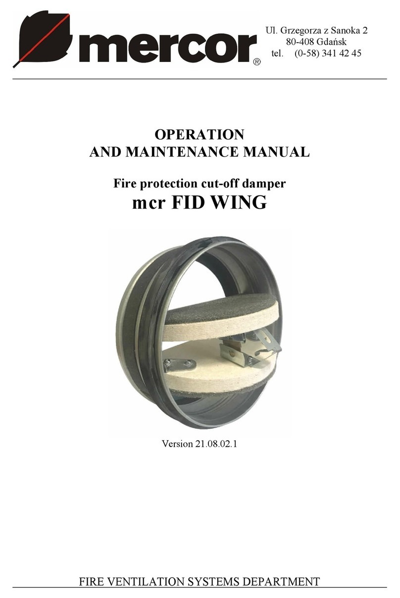
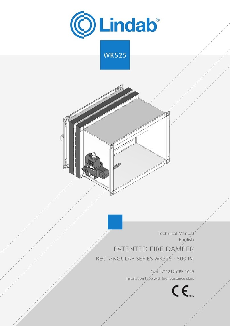
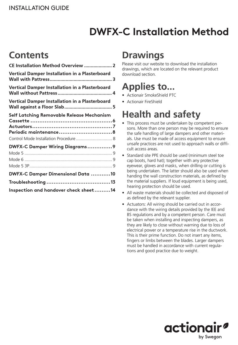
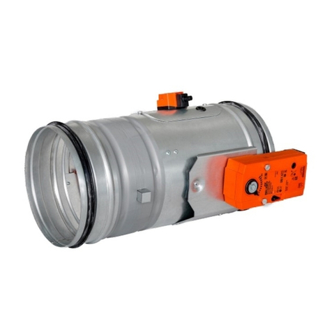
Mandik VCDM Manual

www.mandik.co.uk
MANDÍK, a. s. • Dobříšská 550 • 267 24 Hostomice • Czech Republic • Tel.: +420 311 706 742 • E-Mail: [email protected]
Manufacturer
MANDIK UK Ltd • 130 Aztec West • Bristol BS32 4UB • United Kingdom • Tel.: +44 117 4526376 • E-Mail: [email protected]
Authorized representative
VCDM
Volume control damper
Technical Documentation
Installation, Commissioning, Operation, Maintenance and Service Manual
TPM 167/23
Version 2023-02-14

Volume control damper - VCDMPage 2 Version 2023-02-14
TPM 167/23
These technical specifications state a row of manufactured sizes and models of volume control damper VCDM. It is valid
for production, designing, ordering, delivery, maintenance and operation.
CONTENT
I. GENERAL.....................................................................................................................................................................................3
Description..............................................................................................................................................................................3
Design.....................................................................................................................................................................................4
Design with manual control.................................................................................................................................................4
Dimensions.............................................................................................................................................................................5
Technical parameters..............................................................................................................................................................6
Placement and Assembly........................................................................................................................................................7
II. TECHNICAL DATA.......................................................................................................................................................................8
Pressure loss...........................................................................................................................................................................8
Noise data - level of acoustic output corrected with filter A..................................................................................................9
III. MATERIAL, FINISHING.............................................................................................................................................................10
Material................................................................................................................................................................................10
IV. INSPECTION, TESTING.............................................................................................................................................................10
V. TRANSPORTATION AND STORAGE...........................................................................................................................................10
Logistic terms........................................................................................................................................................................10
VI. ASSEMBLY, ATTENDANCE AND MAINTENANCE......................................................................................................................11
Assembly...............................................................................................................................................................................11
Entry into service and revisions.........................................................................................................................................11
Spare parts.........................................................................................................................................................................11
VII. ORDERING INFORMATION.....................................................................................................................................................11
Ordering key.........................................................................................................................................................................11

Page 3Version 2023-02-14 Volume control damper - VCDM
TPM 167/23
I. GENERAL
Description
Damper characteristics
■Tested in accordance with EN 1366-1, Type B for 120 minutes.
■External Casing leakage class B, Internal leakage min. class 3 acc. to EN 1751
■Please Note: The damper will require a Flamebar BW11 or BW18 coating to achieve fire resistance to BS EN 1366-1.
Working conditions
■Exact damper function is provided under the following conditions
■maximum air velocity 12 m/s
■underpressure max. -1500 Pa or overpressure max. 500 Pa
■Dampers are installed with the horizontal or vertical axis of the blades.
■Dampers are suitable for systems without abrasive, chemical and adhesive particles.
■Dampers are designed for macroclimatic areas with mild climate according to EN IEC 60 721-3-3 ed.2., class 3K22.
■Temperature in the place of installation is permitted to range from -20°C to +50°C.
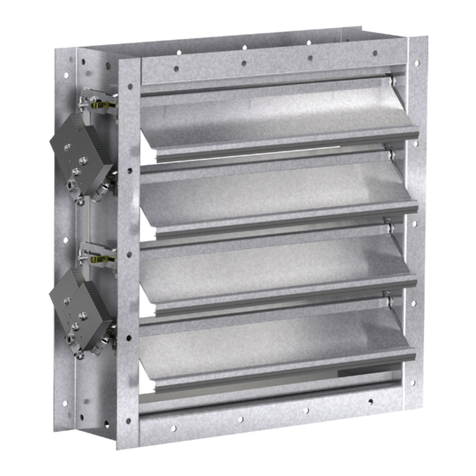
The Mandik VCDM is a volume control damper suitable for
use at high temperatures.
The VCDM can be used to control and balance the airflow
through connecting ductwork and has been tested for high
temperature applications.
The VCDM is available in sizes from 200x200 to 1200x1200 as
a single unit.
The damper comes equipped with a manual handle which can
be sent incrementally to set the position of the blades.
An extended spindle allows for the damper to be insulated to
meet the requirements of the ductwork.
Damper VCDM

Volume control damper - VCDMPage 4 Version 2023-02-14
TPM 167/23
Design
Design with manual control
■Design with manual control with which actuates the
shutting device
Design .01
Design .01
Damper blades
is closed
Damper blades
is open

Page 5Version 2023-02-14 Volume control damper - VCDM
TPM 167/23
Dimensions
1 Damper body
2 Damper blade
3 Manual control
Flange with corner hole
Flanges of dampers are 30 mm wide with oval hole.
Damper VCDM

Volume control damper - VCDMPage 6 Version 2023-02-14
TPM 167/23
Technical parameters
A x B
[mm]
Number of
blades
Weight
[kg]
Effective
area Sef
[m2]
A x B
[mm]
Number of
blades
Weight
[kg]
Effective
area Sef
[m2]
200
x
200 1 14,3 0,0227
400
x
200 1 17,6 0,0511
250 2 16,4 0,0270 250 2 20,3 0,0608
300 2 17,3 0,0350 300 2 21,5 0,0788
350 2 18,3 0,0430 350 2 22,6 0,0968
400 2 19,2 0,0510 400 2 23,8 0,1148
450 3 21,2 0,0554 450 3 26,4 0,1246
500 3 22,2 0,0634 500 3 27,6 0,1426
600 3 24,1 0,0794 600 3 30,0 0,1786
700 4 27,0 0,0917 700 4 33,7 0,2063
800 4 28,9 0,1077 800 4 36,1 0,2423
900 5 34,5 0,1200 900 5 42,5 0,2700
1000 5 36,4 0,1360 1000 5 44,8 0,3060
1100 6 39,3 0,1483 1100 6 48,6 0,3337
1200 6 41,2 0,1643 1200 6 51,0 0,3697
250
x
200 1 15,1 0,0298
450
x
200 1 18,4 0,0582
250 2 17,4 0,0355 250 2 21,3 0,0693
300 2 18,4 0,0460 300 2 22,5 0,0898
350 2 19,4 0,0565 350 2 23,7 0,1103
400 2 20,4 0,0670 400 2 25,0 0,1308
450 3 22,5 0,0727 450 3 27,7 0,1419
500 3 23,5 0,0832 500 3 28,9 0,1624
600 3 25,5 0,1042 600 3 31,4 0,2034
700 4 28,7 0,1203 700 4 38,0 0,2349
800 4 30,7 0,1413 800 4 40,5 0,2759
900 5 36,5 0,1575 900 5 44,5 0,3075
1000 5 38,5 0,1785 1000 5 47,0 0,3485
1100 6 41,6 0,1947 1100 6 50,9 0,3801
1200 6 43,6 0,2157 1200 6 53,4 0,4211
300
x
200 1 15,9 0,0369
500
x
200 1 19,2 0,0653
250 2 18,3 0,0439 250 2 22,2 0,0777
300 2 19,4 0,0569 300 2 23,5 0,1007
350 2 20,5 0,0699 350 2 24,8 0,1237
400 2 21,5 0,0829 400 2 26,1 0,1467
450 3 23,8 0,0900 450 3 29,0 0,1592
500 3 24,9 0,1030 500 3 30,3 0,1822
600 3 27,0 0,1290 600 3 32,9 0,2282
700 4 30,3 0,1490 700 4 39,7 0,2636
800 4 32,5 0,1750 800 4 42,3 0,3096
900 5 38,5 0,1950 900 5 46,5 0,3450
1000 5 40,6 0,2210 1000 5 49,1 0,3910
1100 6 43,9 0,2410 1100 6 53,2 0,4264
1200 6 46,1 0,2670 1200 6 55,8 0,4724
350
x
200 1 16,8 0,0440
600
x
200 1 20,9 0,0795
250 2 19,3 0,0524 250 2 24,2 0,0946
300 2 20,4 0,0679 300 2 25,6 0,1226
350 2 21,6 0,0834 350 2 27,0 0,1506
400 2 22,7 0,0989 400 2 28,4 0,1786
450 3 25,1 0,1073 450 3 31,6 0,1938
500 3 26,2 0,1228 500 3 33,0 0,2218
600 3 28,5 0,1538 600 3 35,8 0,2778
700 4 32,0 0,1776 700 4 43,1 0,3209
800 4 34,3 0,2086 800 4 45,9 0,3769
900 5 40,5 0,2325 900 5 50,5 0,4200
1000 5 42,7 0,2635 1000 5 53,3 0,4760
1100 6 46,3 0,2874 1100 6 57,9 0,5191
1200 6 48,5 0,3184 1200 6 60,7 0,5751

Page 7Version 2023-02-14 Volume control damper - VCDM
TPM 167/23
A x B
[mm]
Number of
blades
Weight
[kg]
Effective
area Sef
[m2]
A x B
[mm]
Number of
blades
Weight
[kg]
Effective
area Sef
[m2]
700
x
200 1 22,5 0,0937
1000
x
200 1 27,5 0,1363
250 2 26,1 0,1115 250 2 32,0 0,1622
300 2 27,7 0,1445 300 2 33,9 0,2102
350 2 29,2 0,1775 350 2 35,7 0,2582
400 2 30,7 0,2105 400 2 37,6 0,3062
450 3 34,2 0,2284 450 3 42,0 0,3322
500 3 35,7 0,2614 500 3 43,9 0,3802
600 3 38,8 0,3274 600 3 50,3 0,4762
700 4 46,4 0,3782 700 4 56,5 0,5501
800 4 49,5 0,4442 800 4 60,3 0,6461
900 5 54,5 0,4950 900 5 66,5 0,7200
1000 5 57,5 0,5610 1000 5 70,2 0,8160
1100 6 62,5 0,6118 1100 6 76,5 0,8899
1200 6 65,6 0,6778 1200 6 80,2 0,9859
800
x
200 1 24,2 0,1079
1100
x
200 1 29,1 0,1505
250 2 28,1 0,1284 250 2 34,0 0,1791
300 2 29,7 0,1664 300 2 35,9 0,2321
350 2 31,4 0,2044 350 2 37,9 0,2851
400 2 33,0 0,2424 400 2 39,9 0,3381
450 3 36,8 0,2630 450 3 47,2 0,3668
500 3 38,4 0,3010 500 3 49,2 0,4198
600 3 41,7 0,3770 600 3 53,2 0,5258
700 4 49,8 0,4355 700 4 59,9 0,6074
800 4 53,1 0,5115 800 4 63,8 0,7134
900 5 58,5 0,5700 900 5 70,5 0,7950
1000 5 61,8 0,6460 1000 5 74,5 0,9010
1100 6 67,2 0,7045 1100 6 81,1 0,9826
1200 6 70,5 0,7805 1200 6 85,1 1,0886
900
x
200 1 25,8 0,1221
1200
x
200 1 30,8 0,1647
250 2 30,0 0,1453 250 2 35,9 0,1960
300 2 31,8 0,1883 300 2 38,0 0,2540
350 2 33,5 0,2313 350 2 40,1 0,3120
400 2 35,3 0,2743 400 2 42,2 0,3700
450 3 39,4 0,2976 450 3 49,8 0,4014
500 3 41,1 0,3406 500 3 51,9 0,4594
600 3 47,3 0,4266 600 3 56,1 0,5754
700 4 53,1 0,4928 700 4 63,2 0,6647
800 4 56,7 0,5788 800 4 67,4 0,7807
900 5 62,5 0,6450 900 5 74,5 0,8700
1000 5 66,0 0,7310 1000 5 78,7 0,9860
1100 6 71,8 0,7972 1100 6 85,8 1,0753
1200 6 75,4 0,8832 1200 6 90,0 1,1913
Placement and Assembly
■Dampers are designed for installation with horizontal or
vertical axis of the blades.
■Dampers can be mounted in ductwork and insulated to
meet the requirements of the ductwork system

Volume control damper - VCDMPage 8 Version 2023-02-14
TPM 167/23
0
10
20
30
40
50
60
70
80
90
100
110
120
2 3 4 5 6 7 8 9 10 11 12
B=200/400/600/800/1000/1200mm B=250mm B=300/450mm B=350/500/700/900/1100mm
w (m/s)
Δps(Pa)
II. TECHNICAL DATA
Pressure loss
Determination of pressure loss by using diagram ρ = 1,2 kg/m3
Δps - static pressure drop
w - air velocity in the free cross section (AxB)
B - height of the damper

Page 9Version 2023-02-14 Volume control damper - VCDM
TPM 167/23
Noise data - level of acoustic output corrected with filter A
Sound power level Lw in dB(A) for B=250/300/450mm, damper fully open
f (Hz) 63 125 250 500 1000 2000 4000 8000 Total
w (m/s)
2 16 24 29 29 28 26 23 9 35
3 25 33 38 38 37 35 32 18 44
4 32 40 45 45 44 42 39 25 51
5 38 46 51 51 50 48 45 31 57
6 42 50 55 55 54 52 49 35 61
7 46 54 59 59 58 56 53 39 65
8 49 57 62 62 61 59 56 42 68
9 50 58 63 63 62 60 57 43 69
10 53 61 66 66 65 63 60 46 72
11 55 63 68 68 67 65 62 48 74
12 57 65 70 70 69 67 64 50 76
w - air velocity in the free cross section (AxB) - i.e. before blades
f - frequency of octave band
Sound power level Lw in dB(A) for B=350/500/700/900/1100mm, damper fully open
f (Hz) 63 125 250 500 1000 2000 4000 8000 Total
w (m/s)
2 15 23 28 28 27 25 22 8 34
3 24 32 37 37 36 34 31 17 43
4 31 39 44 44 43 41 38 24 50
5 36 44 49 49 48 46 43 29 55
6 41 49 54 54 53 51 48 34 60
7 45 53 58 58 57 55 52 38 64
8 48 56 61 61 60 58 55 41 67
9 49 57 62 62 61 59 56 42 68
10 51 59 64 64 63 61 58 44 70
11 53 61 66 66 65 63 60 46 72
12 55 63 68 68 67 65 62 48 74
w - air velocity in the free cross section (AxB) - i.e. before blades
f - frequency of octave band
Sound power level Lw in dB(A) for B=200/400/600/800/1000/1200mm, damper fully open
f (Hz) 63 125 250 500 1000 2000 4000 8000 Total
w (m/s)
2 13 21 26 26 25 23 20 6 32
3 21 29 34 34 33 31 28 14 40
4 28 36 41 41 40 38 35 21 47
5 34 42 47 47 46 44 41 27 53
6 38 46 51 51 50 48 45 31 57
7 42 50 55 55 54 52 49 35 61
8 45 53 58 58 57 55 52 38 64
9 47 55 60 60 59 57 54 40 66
10 48 56 61 61 60 58 55 41 67
11 50 58 63 63 62 60 57 43 69
12 52 60 65 65 64 62 59 45 71
w - air velocity in the free cross section (AxB) - i.e. before blades
f - frequency of octave band

Volume control damper - VCDMPage 10 Version 2023-02-14
TPM 167/23
III. MATERIAL, FINISHING
Material
■Damper casing and damper blade are made of galvanized sheet metal without any other surface finish.
■Fasteners are galvanized.
■According to the customer's requirements, damper can be made of stainless material.
Specifications for stainless-steel models – classification of stainless steel:
■Class A2 – Food-grade stainless steel (AISI 304 – EN 17240)
■Class A4 – Chemistry-grade stainless steel (AISI 316, 316L – EN 17346, 17349)
The respective stainless steel is the material for all components present or accessing the damper interior; components
outside the damper body are typically from galvanised sheet metal.
The following components, including the fasteners, are made from stainless steel at all times:
■Damper body and all components permanently attached
■Blade´s holders, including pins, metal parts of blade
Plastic, rubber and silicon components, sealants, foaming bands, glass-ceramic seals, housings, brass bearings of the blade,
actuators, and end switches are identical for all material variants of the dampers.
Some fasteners and components are available in one class of stainless steel; the type will be used in all stainless-steel
variants.
Any other requirements for the design shall be considered atypical and shall be addressed on an individual basis.
IV. INSPECTION, TESTING
■The appliance is constructed and preset by the manufacturer, its operation is dependent on proper installation and
adjustment.
V. TRANSPORTATION AND STORAGE
Logistic terms
■Dampers are delivered on a pallets. As standard, the
dampers are wrapped in plastic foil for protection during
transport and must not be used for long-term storage of
the equipment . Changes in temperature during transport
may cause condensation of water vapour inside the
packaging and thereby condisitions may arise inside the
packaging that are suitable for corrosion of materials used
in the equipment (e.g. white corrosion on zinc-coated
items or mould on calcium silicate). Therefore, it is necess-
ary to remove the transport packaging immediately after
unloading to allow air to circulate around the product.
■The equipment must be stored in clean, dry, well
ventilated and dust-free environment out of direct sun-
light. ensuring protection against moisture and extremes
of temperatures (minumum temperature +5°C) the equip-
ment must be protected against mechanical and accid-
ental damage prior to installation.
■Another required packaging system should be approved
and agreed by manufacturer. Packaging material is not
returnable in case that another packaging system
(material) is required and used and it is not included into
final price of damper.
■For unloading and further manipulation with the damper
is necessary to use appropriate tooling (forklifts) due to
damper weight. Dampers are fragile.
■Dampers are transported by box freight vehicles without
direct weather impact, there must not occur any shocks
and ambient temperature must not exceed +50°C.
Dampers must be protected against impact when
transported and manipulated. During transportation, the
damper blade must be in the "CLOSED" position.
■Dampers are stored indoor in environment without any
aggressive vapours, gases or dust. Indoor temperature
must be in the range from -30°C to +50°C and maximum
relative humidity 95% (avoid condensation on the damper
body). Dampers must be protected against impact when
transported and manipulated.

Page 11Version 2023-02-14 Volume control damper - VCDM
TPM 167/23
VI. ASSEMBLY, ATTENDANCE AND MAINTENANCE
Assembly
■Assembly, maintenance and damper function check can
be done only by qualified and trained person, i.e.
“AUTHORIZED PERSON” according to the manufacturer
documentation. All works done on the fire dampers must
be done according international and local norms and laws.
■All effective safety standards and directives must be
observed during damper assembly.
Entry into service and revisions
■Before entering the dampers into operation after
assembly and after sequential revisions, checks and
functionality tests. After entering into operation, these
revisions must be done according to requirement set by
national regulations.
■In case that dampers are found unable to serve for their
function for any cause, it must be clearly marked. The
operator is obliged to ensure that the damper is put into
condition in which it is ready for function.
Spare parts
■Spare parts are supplied only on basis of an order.
VII. ORDERING INFORMATION
Ordering key
VCDM 200x200 - .01
EXAMPLE:
VCDM 200x200 - .01 - 200x200-damper size, .01-damper design
design
size AxB
Dampers design Additional digit
Manual control .01

www.mandik.co.uk
The producer reserves the right for innovations of the product.
For actual product information see www.mandik.co.uk
MANDÍK, a. s. • Dobříšská 550 • 267 24 Hostomice • Czech Republic • Tel.: +420 311 706 742 • E-Mail: [email protected]
Manufacturer
MANDIK UK Ltd • 130 Aztec West • Bristol BS32 4UB • United Kingdom • Tel.: +44 117 4526376 • E-Mail: [email protected]
Authorized representative
Table of contents
Other Mandik Fire And Smoke Damper manuals

Mandik
Mandik FDMQ User manual

Mandik
Mandik SEDS-R User manual

Mandik
Mandik FDMB User manual

Mandik
Mandik FDMB User manual

Mandik
Mandik FDMS User manual

Mandik
Mandik FDMR User manual

Mandik
Mandik CFDM User manual

Mandik
Mandik SEDM User manual
Mandik
Mandik MSD Square Configuration guide
Mandik
Mandik FDMA User manual
Popular Fire And Smoke Damper manuals by other brands
BLAUBERG Ventilatoren
BLAUBERG Ventilatoren BSK user manual

EKOVENT
EKOVENT EKO-SRBG1 Installation and maintenance instructions
ETS NORD
ETS NORD FDMA-PM Series manual

mercor
mercor mcr S-THERM C Operation and maintenance manual

Slant/Fin
Slant/Fin JA Series Instructions for installation

Greenheck
Greenheck FSDR Series Installation, operation and maintenance manual