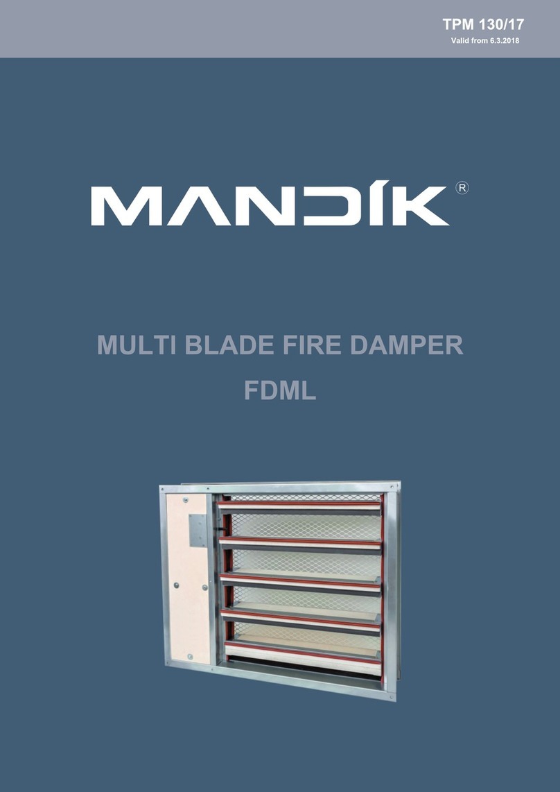
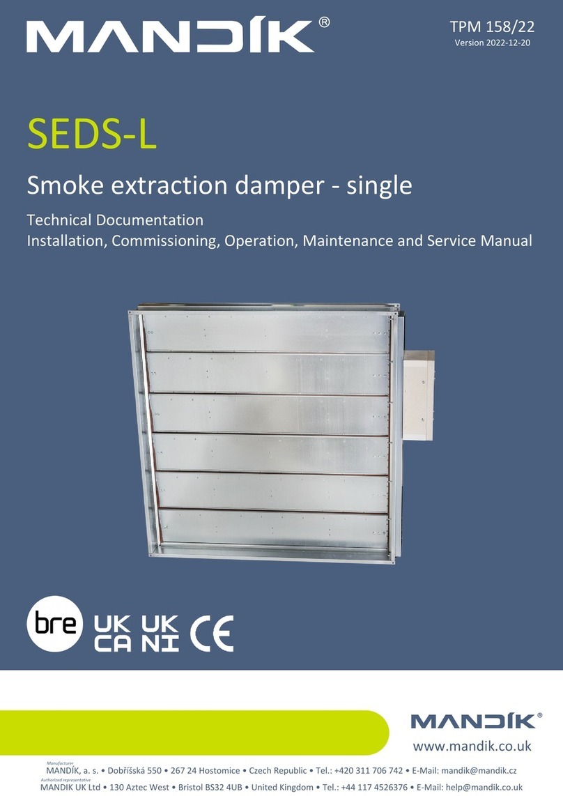
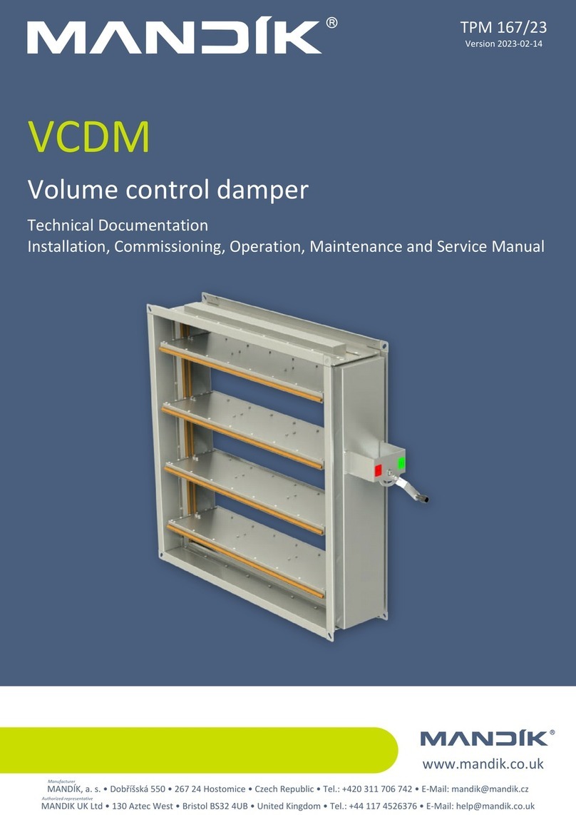
Mandik SEDM-L User manual


2
These technical conditions stipulate a number of manufactured sizes, main dimensions, design and range of use of
multi-slat smoke and heat extraction dampers - multi SEDM-L (hereinafter only dampers). They're binding for production,
design, ordering, delivery, storage, assembly, operation, maintenance and serviceability checks.
1. Description.........................................................................................................................
3
2. Design................................................................................................................................
5
3. Communication and control devices....................................................................................
11
4. Dimensions, weights and effective area..............................................................................
12
5. Placement and Assembly....................................................................................................
18
6. Statement of installations....................................................................................................
25
7. Suspension system……………......................................................................................….
44
8. Pressure loss......................................................................................................................
49
9. Coefficient of local pressure loss.........................................................................................
50
10. Noise data.........................................................................................................................
54
11. Material.............................................................................................................................
58
12. Inspection.........................................................................................................................
58
13. Testing..............................................................................................................................
58
14. Logistic terms....................................................................................................................
59
15. Warranty...........................................................................................................................
59
16. Assembly..........................................................................................................................
59
17. Entry into service and revisions.........................................................................................
60
18. Spare parts.......................................................................................................................
60
19. Ordering key.....................................................................................................................
61
20. Data label...........................................................................................….......……........….
62

3
Smoke and heat extraction dampers - multi are closures in the ductwork of smoke extraction
devices. In the event of a fire, the smoke and heat removal system open the dampers in the
affected section, therefore enabling the extraction fans to remove combustion products and heat
from the endangered areas.
The damper slat is controlled by an actuator.
The damper is fire resistant and is designed for systems with automatic or manual activation.
Smoke dampers are intended for use in spaces with multiple fire compartments, which can be
connected by a smoke extraction duct tested according to EN 1366-8 or can be installed in the
construction of the fire compartment.
The dampers can be supplied with flange(s) or without flange(s), with cover grille(s).
Flanges and grilles are not installed on the damper, they are included loosen. Flanges are
required to fit the cover grilles. Grills and flanges must be installed to the dampers only after
installation of the damper into the wall.
In normal operation, the SEDM-L dampers remain closed. If necessary, in the event of a fire, the
SEDM-L dampers in the affected fire section will open completely so that the smoke can be
removed. When the smoke and heat removal dampers are activated, the dampers used for air
supply in the affected section open. The dampers used to supply air in the affected fire section
are installed at the ground. The dampers are controlled from the central control system on the
basis of signals, e.g. from smoke detectors. The use of cables with a certain fire resistance for the
supply voltage ensures that the actuator is supplied even in the event of a fire.
During ventilation, SEDM-L dampers in the smoke and heat extraction system are controlled by
a control system, it's possible to fully open, close or continuously control the flow. The SEDM-L
dampers, which are used for air supply, remain closed during ventilation.
Position:
1 SEDM-L
2 Ventilation grille or damper for smoke and heat removal from one section
3
Air inlet
4 Smoke barrier
5 Fan for forced smoke and heat removal
6 Duct for smoke extraction from one section
7 Multi-section smoke extraction duct

4
The damper's faultless operation is ensured under the following conditions:
a) maximum air flow speed 12 m/s
b) maximum vacuum up to 1000 Pa or overpressure up to 500 Pa
The dampers are suitable for installing in a vertical position, with the slat axis horizontal.
The dampers are designed for environments protected against weather conditions with class 3K5
climatic conditions, without condensation, icing, ice formation, without water and from sources
other than rain and with a temperature limit of -30°C to 50°C.
• CE certification according to EN 12101-8
• tested according to EN 1366-10
• classified according to EN 13501-4 + A1
• fire resistance according Tab. 1.3.1
• pressure class 2 (vacuum 1000 Pa / overpressure 500 Pa)
• tightness according to EN 1751 via body class C and via damper slat min. class 3
• Cmod cycling according to EN 12101-8
• Certificate of Constancy of Properties No. 1391-CPR-2021/0009
• Performance declaration No. PM/SEDM-L/01/22/1
• Hygienic assessment of fire dampers - Report No. 1.6/pos/21/19b
In a solid wall construction and on duct in a solid wall
construction, th. 100 mm
For duct in a solid wall construction, th. 100 mm
In gypsum wall construction and on the duct in gypsum
wall construction, th. 100 mm

5
Belimo actuators are used for dampers, series BEN, BEE, BE for 230V AC resp. 24 V AC/DC.
After connection to the power supply voltage, the actuator moves the damper slats to the "OPEN" position
or "CLOSED" (according to the corresponding connection, see wiring diagram). If the power supply is
interrupted, the actuator stops at the current position. The signalling of the "OPEN" and "CLOSED" damper
slats positions is ensured by two built-in fixed “potential-free” end- limit switches.
The actuator for operating the damper slats is mounted in an insulated cover/box. It is accessible
after removing the cover lid. The electrical connection of the actuator is made with a non-flammable cable
(or a cable located in the adjoining cable duct), which passes through an opening made in the wall of the
insulated cover/box when installing the damper or when connecting the actuator power cable. The cable
entry must meet a minimum fire resistance of 30 minutes.
Position:
1 Damper housing
2 Slats
3 Silicone slat seal
4 Internal silicone seal
5 Fire-fighting foam tape
6 Slat stop
7
Actuator housing
8
Actuator housing cover
9
Actuator
Belimo modulating actuators, BEN (BEE)-SR series for 24V AC/DC are specially designed for remote control
of fire dampers. The position of the damper slats is adjustable by means of control voltage 0 (2)...10V DC.
The signalling of the "OPEN" and "CLOSED" damper slats positions is ensured by two built-in fixed
“potential-free” limit switches.
The actuator for operating the damper slats is mounted in an insulated cover/box. It is accessible after
removing the cover lid. The electrical connection of the actuator is made with non-flammable cables (or
cables located in the adjoining cable duct), which pass through an opening made in the wall of the insulated
cover when installing the damper or when connecting the power cables of the actuator. The cable entry must
meet a minimum fire resistance of 30 minutes.

6
Power voltage AC/DC 24 V
50/60Hz
AC/DC 24 V
50/60Hz
AC 230 V
50/60Hz
Power consumption - in operation
- in the end position
3 W
0,1 W
3 W
0,3 W
4 W
0,4 W
Dimensioning 6 VA (Imax 8,2 A @ 5 ms) 6,5 VA (Imax 8.2 A @ 5 ms) 7 VA (Imax 4 A @ 5 ms)
Protection class III III II
Degree of protection IP 54
Adjustment time for 95° < 30 s
Ambient temperature
Storage temperature
-30°C … +55°C
-40°C … +80°C
Connection - drive
- auxiliary switch
Cable 1 m, 3 x 0,75 mm2
Cable 1 m, 6 x 0,75 mm2
(BEN 24-ST) with plug
connectors
Cable 1 m, 4 x 0,75 mm2
Cable 1 m, 6 x 0,75 mm2
Cable 1 m, 3 x 0,75 mm2
Cable 1 m, 6 x 0,75 mm2
S2S1 S3 S5S4 S6
2
13
<5° <80°
S2S1 S3 S5S4 S6
2
13
<5° <80°
N L1
S2S1 S3 S5S4 S6
2
13
<5° <80°
5
Y
U
DC (0)2...10 V
DC 2...10 V

7
S2S1 S3 S5S4 S6
2
13
<5° <80°
S2S1 S3 S5S4 S6
2
13
<5° <80°
N L1
S2S1 S3 S5S4 S6
2
13
<5° <80°
5
Y
U
DC (0)2...10 V
DC 2...10 V
Power voltage AC/DC 24 V
50/60Hz
AC/DC 24 V
50/60Hz
AC 230 V
50/60Hz
Power consumption - in operation
- in the end position
2,5 W
0,1 W
3 W
0,3 W
3,5 W
0,4 W
Dimensioning 5 VA (Imax 8,2 A @ 5 ms) 5,5 VA (Imax 8.2 A @ 5 ms) 6 VA (Imax 4 A @ 5 ms)
Protection class III III II
Degree of protection IP 54
Adjustment time for 95° < 60 s
Ambient temperature
Storage temperature
-30°C … +55°C
-40°C … +80°C
Connection - drive
- auxiliary switch
Cable 1 m, 3 x 0,75 mm2
Cable 1 m, 6 x 0,75 mm2
(BEE 24-ST) with plug
connectors
Cable 1 m, 4 x 0,75 mm2
Cable 1 m, 6 x 0,75 mm2
Cable 1 m, 3 x 0,75 mm2
Cable 1 m, 6 x 0,75 mm2

8
S2S1 S3 S5S4 S6
2
13
<3° <87°
S2S1 S3 S5S4 S6
2
13
<3° <87°
N L1
Power voltage AC/DC 24 V
50/60Hz
AC 230 V
50/60Hz
Power consumption - in operation
- in the end position
12 W
0,5 W
8 W
0,5 W
Dimensioning 18 VA (Imax 8,2 A @ 5 ms) 15 VA (Imax 7,9 A @ 5 ms)
Protection class III II
Degree of protection IP 54
Adjustment time for 95° < 60 s
Ambient temperature
Storage temperature
-30°C … +50°C
-40°C … +80°C
Connection - drive
- auxiliary switch
Cable 1 m, 3 x 0,75 mm2
Cable 1 m, 6 x 0,75 mm2
(BE 24-ST) with plug
connectors

9
Position:
1 Damper housing
2 Slats
3 Silicone slat seal
4 Internal silicone seal
5 Fire-fighting foam tape
6 Slat stop
7
Actuator housing
8
Actuator housing cover
9
Actuator
10 Communication and power supply device BKNE 230-24
Design with communication and power supply device BKNE 230-24 and with actuator BEN (BEE, BE)-ST for 24V.
The BKNE 230-24 serves on the one hand as a decentralized network device for powering the actuator and on the other
hand transmits the signal of the communication and control device BKSE 24-6.
It simplifies electrical installation and connection of dampers. In the meantime, it facilitates “on-site inspection” and allows
central control and inspection of dampers using a simple 2-wire line.
The BKNE 230-24 transmits the "OPEN" / "CLOSED" damper position (switches in the actuator) and fault messages to
the BKSE 24-6. It also receives commands from the control device and controls the adjustment of the actuator to the
desired position. The last control command will be retained even after a temporary network failure..
The BKNE 230-24 controls the switching position of the actuator, its adjustment time and the data exchange with the
BKSE 24-6. In addition, it controls the actuator current (actuator connection) and the power supply.
To simplify the connection, the actuator is equipped with plug connectors that plug directly into the BKNE 230-24.
The actuator, communication and power supply device BKNE 230-24 are mounted in an insulated cover, they are
accessible after removing the cover. The electrical connection of the actuator and the BKNE 230-24 communication and
power supply device is made with a non-flammable cable (or a cable located in an adjoining cable duct), the two-wire
BKNE 230-24 cable should be connected to terminals 6 and 7. It is also recommended to use cable, which is used for fire
signalling network. The cables pass through an opening made in the wall of the insulated cover when installing the damper
or when connecting the actuator power cable. The cable entry must meet a minimum fire resistance of 30 minutes.
For more information on actuators and devices, see the Belimo catalogue.

10
Power voltage AC 230V 50/60Hz
Power consumption 10 W (including actuator)
Dimensioning 19 VA (including actuator)
Protection class II
Ambient operation temperature
Storage temperature
-30°C … +50°C
-40°C … +80°C
Connection - network
- drive
- terminal blocks
cable 1 m without plug
6-pin plug, 3-pin plug
screw terminals for 2x1.5 mm2 conductor
1
2
3
4
5
6
7b
a
AC 230 V
1 to 5 should not be
connected
two-wire line to
BKSE 24-6
yellow flashing damper rotates to the open position
yellow lit-up damper is open
green flashing damper rotates to the closed position
green lit-up damper is closed
yellow or green flashes twice as often fault
yellow + green dark network outage

11
indicates operating condition and faults of flue dampers. These conditions can be
signalled or transmitted to the higher-level control system via the auxiliary built-in contacts.
Signals from individual BKNE 230-24 are evaluated separately. All BKNE 230-24 are controlled
simultaneously. A maximum of 6 BKNE 230-24 can be connected to the BKSE 24-6.
Damper control is ensured with a simple 2-wire line. The damper's correct function is indicated by
two LEDs. The operating status of the entire control system and any errors are indicated by these
LEDs and the corresponding error LED.
Mounting and connection of BKSE 24-6 can be done on a 35mm DIN rail. It's connected using
two 9-pin terminal blocks (plug connectors).
Power voltage AC 24 V 50/60Hz
Power consumption 3,5 W (operating position)
Dimensioning 5,5 VA 18 VA (Imax 6.4 A @ 2.5 ms)
Protection class III (low voltage)
Degree of protection IP 20
Ambient operation temperature 0 … +50°C
Connection screw terminals for 2x1.5 mm2 conductor
17
~
AC 24 V
18
15
16
13
14
2
1
4
3
6
5
7
9
8
11
12
10
+
-
U
a1...a6
BKNE 230-24
a1...a6
Input 1 Input 2
(galvanically isolated)
SMOKING
AUTO
END OF SMOKING
COM
delay 0 s (fan)
delay 60 s (fan)
OPEN
CLOSED
* Error
* reverse output: fault = contact open

12

13
A
A
30
A (B)
17
10
10
X
A-A
Detail X
Detail Y
B
B
B-B
Y

14

15
2
0,0537 39,0 1,8 2,0 0,9 1,4
BEN
(15 N.m)
0,0682 40,7 1,9 2,1 1,0 1,5
0,0827 42,4 2,0 2,2 1,1 1,6
0,0972 44,3 2,1 2,3 1,2 1,7
0,1117 45,9 2,2 2,4 1,3 1,8
0,1262 47,6 2,3 2,5 1,4 1,9
0,1407 49,3 2,4 2,6 1,5 2,0
0,1552 51,0 2,5 2,7 1,6 2,1
0,1697 52,7 2,6 2,7 1,7 2,2
0,1842 54,8 2,7 2,8 1,8 2,3
0,1987 56,5 2,8 2,9 1,9 2,4
0,2132 59,8 2,9 3,0 2,0 2,5
0,2277 61,5 2,9 3,1 2,1 2,6
0,2422 63,2 3,0 3,2 2,2 2,7
0,2567 64,9 3,1 3,3 2,3 2,8
0,2712 66,9 3,2 3,4 2,4 3,0
0,2857 68,6 3,4 3,5 2,5 3,1
0,3002 70,3 3,5 3,6 2,6 3,2
0,3147 72,0 3,6 3,7 2,7 3,3
0,3292 73,7 3,7 3,8 2,8 3,4
0,3437 75,4 3,8 3,9 3,0 3,5
3
0,0833 50,3 2,2 2,4 1,2 1,8
BEN
(15 N.m)
0,1058 52,3 2,3 2,5 1,3 1,9
0,1283 54,4 2,4 2,6 1,4 2,0
0,1508 56,6 2,5 2,7 1,6 2,2
0,1733 58,6 2,6 2,7 1,7 2,3
0,1958 60,7 2,7 2,8 1,8 2,4
0,2183 62,7 2,8 2,9 1,9 2,5
0,2408 64,8 2,9 3,0 2,0 2,7
0,2633 66,8 3,0 3,1 2,2 2,8
0,2858 70,9 3,1 3,2 2,3 2,9
0,3083 72,9 3,2 3,3 2,4 3,0
0,3308 74,9 3,3 3,4 2,5 3,2
0,3533 77,0 3,3 3,5 2,7 3,4
0,3758 79,0 3,4 3,6 2,8 3,5
0,3983 81,1 3,5 3,7 2,9 3,6
0,4208 83,5 3,6 3,8 3,0 3,8
BEE
(25 N.m)
0,4433 86,7 3,7 3,9 3,4 3,9
0,4658 88,7 3,9 3,9 3,5 4,0
0,4883 90,8 4,0 4,0 3,6 4,1
0,5108 92,8 4,1 4,1 3,8 4,3
0,5333 94,9 4,2 4,2 3,9 4,4
4
0,1129 61,8 2,6 2,7 1,5 2,2
BEN
(15 N.m)
0,1434 64,2 2,7 2,8 1,6 2,3
0,1739 66,6 2,8 2,9 1,8 2,5
0,2044 69,2 2,9 3,0 1,9 2,6
0,2349 71,6 3,0 3,1 2,1 2,8
0,2654 74,0 3,1 3,2 2,2 2,9
0,2959 76,4 3,2 3,3 2,4 3,1
0,3264 80,4 3,3 3,4 2,5 3,2
0,3569 82,8 3,4 3,5 2,7 3,4
0,3874 85,5 3,5 3,6 2,8 3,5
0,4179 87,9 3,6 3,7 2,9 3,7
BEE
(25 N.m)
0,4484 91,5 3,7 3,8 3,1 3,8
0,4789 93,9 3,7 3,9 3,2 4,1
0,5094 96,3 3,8 3,9 3,4 4,3
0,5399 98,7 3,9 4,0 3,5 4,4
0,5704 101,9 4,0 4,1 3,7 4,6
0,6009 104,3 4,2 4,2 4,1 4,7
0,6314 106,7 4,3 4,3 4,3 4,9
0,6619 109,1 4,4 4,4 4,4 5,0
0,6924 111,5 4,5 4,5 4,6 5,2
0,7229 113,9 4,6 4,6 4,7 5,3

16
5
0,1425 74,1 3,0 3,1 1,8 2,6
BEN
(15 N.m)
0,1810 76,8 3,1 3,2 1,9 2,9
0,2195 79,6 3,2 3,3 2,1 3,1
0,2580 82,6 3,3 3,4 2,3 3,3
0,2965 85,3 3,4 3,5 2,4 3,5
0,3350 89,7 3,5 3,6 2,6 3,7
0,3735 92,4 3,5 3,7 3,0 3,9
BEE
(25 N.m)
0,4120 95,2 3,6 3,8 3,2 4,1
0,4505 99,1 3,7 3,9 3,3 4,3
0,4890 102,4 3,8 3,9 3,5 4,4
0,5275 105,2 3,9 4,0 3,7 4,6
0,5660 108,3 4,0 4,1 3,9 4,8
0,6045 111,1 4,1 4,2 4,1 5,4
0,6430 113,9 4,2 4,3 4,3 5,6
0,6815 116,6 4,3 4,4 4,5 5,8
0,7200 120,0 4,4 4,5 4,7 5,9
0,7585 122,7 4,5 4,6 5,2 6,1
BE
(40 N.m)
0,7970 125,5 4,6 4,7 5,4 6,3
0,8355 128,2 4,7 4,8 5,6 6,5
0,8740 131,0 4,8 4,9 5,8 6,7
0,9125 133,8 4,9 5,0 6,0 6,9
6
0,1721 85,3 3,4 3,5 2,1 3,1 BEN
(15 N.m)
0,2186 88,4 3,5 3,6 2,3 3,4
0,2651 91,5 3,6 3,7 2,4 3,6
0,3116 94,9 3,7 3,8 2,6 3,8
BEE
(25 N.m)
0,3581 98,0 3,8 3,9 2,8 4,0
0,4046 102,7 3,9 4,0 3,2 4,2
0,4511 107,0 4,0 4,0 3,4 4,4
0,4976 110,1 4,1 4,1 3,6 4,6
0,5441 113,2 4,2 4,2 3,8 4,9
0,5906 117,3 4,2 4,3 4,0 5,1
0,6371 120,4 4,3 4,4 4,2 5,3
0,6836 123,5 4,5 4,5 4,5 5,5
0,7301 126,7 4,5 4,6 4,7 6,1
0,7766 129,8 4,6 4,7 4,9 6,3
BE
(40 N.m)
0,8231 132,9 4,7 4,8 5,1 6,6
0,8696 136,6 4,8 4,9 5,3 6,8
0,9161 139,7 4,9 5,0 5,9 7,0
0,9626 142,8 5,0 5,1 6,2 7,2
1,0091 145,9 5,1 5,2 6,4 7,4
1,0556 149,0 5,3 5,2 6,6 7,6
1,1021 152,1 5,4 5,3 6,8 7,8
7
0,2017 96,7 3,7 3,9 2,3 3,5 BEN
(15 N.m)
0,2562 100,2 3,8 3,9 2,6 3,8
0,3107 103,6 3,9 4,0 2,8 4,0
BEE
(25 N.m)
0,3652 109,0 4,0 4,1 3,1 4,2
0,4197 112,4 4,1 4,2 3,4 4,5
0,4742 117,0 4,2 4,3 3,6 4,7
0,5287 120,5 4,3 4,4 3,8 5,0
0,5832 124,4 4,4 4,5 4,1 5,2
0,6377 127,9 4,5 4,6 4,3 5,4
0,6922 132,0 4,6 4,7 4,5 5,7
0,7467 135,4 4,7 4,8 4,8 5,9
0,8012 138,9 4,8 4,9 5,0 6,1
BE
(40 N.m)
0,8557 142,3 4,9 5,0 5,2 6,9
0,9102 145,8 5,0 5,1 5,5 7,1
0,9647 149,2 5,1 5,1 5,7 7,3
1,0192 153,3 5,2 5,2 5,9 7,6
1,0737 156,7 5,3 5,3 6,7 7,8
1,1282 160,2 5,4 5,4 6,9 8,0
1,1827 163,7 5,5 5,5 7,1 8,3
1,2372 167,1 5,6 5,6 7,4 8,5
1,2917 170,6 5,7 5,7 7,6 8,7

17
8
0,2313 108,1 4,2 4,2 2,6 3,9
BEE
(25 N.m)
0,2938 111,9 4,3 4,3 2,9 4,2
0,3563 115,7 4,4 4,4 3,1 4,5
0,4188 121,4 4,4 4,5 3,5 4,7
0,4813 126,4 4,5 4,6 3,7 5,0
0,5438 130,2 4,7 4,7 4,0 5,2
0,6063 134,0 4,7 4,8 4,3 5,5
0,6688 138,4 4,8 4,9 4,5 5,8
0,7313 142,2 4,9 5,0 4,8 6,0
0,7938 146,6 5,0 5,1 5,0 6,3
BE
(40 N.m)
0,8563 150,4 5,1 5,2 5,3 6,5
0,9188 154,2 5,2 5,2 5,5 6,8
0,9813 158,0 5,3 5,3 5,8 7,6
1,0438 161,8 5,4 5,4 6,1 7,9
1,1063 165,6 5,5 5,5 6,3 8,1
1,1688 170,0 5,6 5,6 6,6 8,4
1,2313 173,8 5,7 5,7 7,4 8,7
1,2938 177,6 5,8 5,8 7,7 8,9
1,3563 181,4 5,9 5,9 7,9 9,2
1,4188 185,3 6,0 6,0 8,2 9,4
1,4813 189,1 6,1 6,1 8,4 9,7
9
0,2609 120,2 4,6 4,6 2,9 4,3
BEE
(25 N.m)
0,3314 124,3 4,7 4,7 3,2 4,6
0,4019 128,5 4,8 4,8 3,6 4,9
0,4724 135,8 4,9 4,9 3,8 5,2
0,5429 139,9 5,0 5,0 4,1 5,5
0,6134 144,1 5,1 5,1 4,4 5,8
0,6839 148,2 5,1 5,2 4,7 6,0
0,7544 153,0 5,3 5,2 5,0 6,3
0,8249 157,2 5,4 5,3 5,3 6,6
BE
(40 N.m)
0,8954 162,1 5,4 5,4 5,5 6,9
0,9659 166,3 5,5 5,5 5,8 7,2
1,0364 170,5 5,6 5,6 6,1 7,5
1,1069 174,6 5,7 5,7 6,4 8,4
1,1774 178,8 5,8 5,8 6,7 8,7
1,2479 182,9 5,9 5,9 6,9 8,9
1,3184 187,9 6,0 6,0 7,2 9,2
1,3889 192,1 6,1 6,1 8,1 9,5
1,4594 196,2 6,2 6,2 8,4 9,8
1,5299 200,4 6,3 6,3 8,7 10,1
1,6004 204,5 6,4 6,4 9,0 10,4
1,6709 208,7 6,5 6,4 9,3 10,6
10
0,2905 131,3 4,9 5,0 3,2 4,7
BEE
(25 N.m)
0,3690 135,8 5,0 5,1 3,6 5,1
0,4475 143,1 5,1 5,2 3,9 5,4
0,5260 148,0 5,2 5,2 4,2 5,7
0,6045 152,5 5,3 5,3 4,5 6,0
0,6830 157,0 5,4 5,4 4,8 6,3
0,7615 161,5 5,5 5,5 5,1 6,6
BE
(40 N.m)
0,8400 166,7 5,6 5,6 5,4 6,9
0,9185 171,2 5,7 5,7 5,7 7,2
0,9970 176,5 5,8 5,8 6,0 7,5
1,0755 181,0 5,9 5,9 6,3 7,8
1,1540 185,5 6,0 6,0 6,6 8,1
1,2325 190,0 6,1 6,1 7,0 9,1
1,3110 194,5 6,2 6,2 7,3 9,4
1,3895 199,1 6,3 6,3 7,6 9,7
1,4680 204,4 6,4 6,3 7,9 10,0
1,5465 208,9 6,5 6,4 8,9 10,4
1,6250 213,4 6,6 6,5 9,2 10,7
1,7035 217,9 6,7 6,6 9,5 11,0
1,7820 222,4 6,8 6,7 9,8 11,3
1,8605 226,9 6,9 6,8 10,1 11,6

18
●They're designed for installation in smoke and heat removal duct according to EN1366-8.
●They're suitable for installation in a vertical position, with the slat axis horizontal.
●Dampers and duct must be suspended separately. The connected piping must be suspended in such
a way that the transfer of all loads from the adjoining ventilation duct to the damper body is completely
excluded. Adjacent duct must be suspended or supported, as required by the duct suppliers.
●o provide the necessary space for access to the control device, it is recommended that other objects
be at least 350 mm away from the control parts of the damper.
●Transport the damper to the installation site in the transport packaging. Pay attention to the appropriate
length of the forks of the forklift /handling equipment/ to avoid breaking of wooden planks, consequently
damaging the damper´s slats.
●Smaller dimensions can be transported, handled and installed into the mounting hole manually, for
dimensions where a handling insert is included in the delivery, it is recommended to use a suitable
handling tools and machines, eg. a forklift.
Position:
1 Damper housing
2 Slat stop
3 Handling inserts (2pc)
4 Slats
5 Board - not included
6 Forks

19

20
X
Detail X
Position:
1
SEDM-L
2 Flange
Detail X
Detail Y
Detail Y
Y
Other manuals for SEDM-L
2
Table of contents
Other Mandik Fire And Smoke Damper manuals
Popular Fire And Smoke Damper manuals by other brands

klimaoprema
klimaoprema FD25 product manual

aldes
aldes CF1 Installation, operation and maintenance manual

klimaoprema
klimaoprema FD product manual

Johnson Controls
Johnson Controls FD-1300 Installation

Carrier
Carrier 48DK024 installation instructions

mercor
mercor mcr WIP EI60S Operation and maintenance manual