marklin 76471 User manual

Lichtsignal
76471/76472/76491/76493/76494
F
D GB USA NL

2
Inhaltsverzeichnis Seite
Signalbilder beim Vorbild 3
Bestimmungsgemäße Verwendung 6
Lieferumfang 6
Sicherheitshinweise 6
Wichtige Hinweise 6
Technische Daten 6
Funktionen 6
Signal-Einbau 7
Programmierung mit CS 2 7
Entsorgung 8
Garantie 8
Betriebsart und Adressen einstellen 18
Aufbau 29
Aufkleber anbringen 39
Table of Contents Page
Signal Aspects in the Prototyp 3
Intended Use of the Product 9
Contents as Delivered 9
Safety Notes 9
Important Notes 9
Technical Data 9
Functions 9
Signal Installation 10
Programming with the CS 2 10
Disposing 11
Warranty 11
Setting the mode of operation and addresses 18
Setup 29
Attach decals 39
Sommaire Page
Positions signalétiques réelles 3
Utilisation conforme 12
Livraison 12
Consignes de sécurité 12
Consignes importantes 12
Caractéristiques techniques 12
Fonctions 12
Montage du signal 13
Programmation avec CS 2 13
Elimination 14
Garantie 14
Définir le mode d’exploitation et les adresses 18
Montage 29
Fixez les autocollants 39
Inhoudsopgave Pagina
Seinbeelden bij het voorbeeld 3
Beoogd gebruik 15
Leveringsomvang 15
Veiligheidsvoorschriften 15
Belangrijke aanwijzingen 15
Technische gegevens 15
Functies 15
Sein inbouwen 16
Programmeren met CS2 16
Afdanken 17
Garantie 17
Bedrijfsmodus en adres instellen 18
Opbouwen 29
Bevestig stickers 39

3
Signalbilder beim Vorbild
Signal Aspects in the Prototyp
Positions signalétiques réelles
Seinbeelden bij het voorbeeld
Signalbild Gleissperrsignal (76471, 76472):
Signal indication of the platform blocking signal (76471, 76472):
Aspect du signal de barrage (76471, 76472):
Seinbeeld hoofdsein (76471, 76472):
Bedeutung:
Meaning:
Signification:
Betekend:
Rangierfahrt erlaubt
Switching Maneuver Allowed
Circulation autorisée
rangeren toegestaan
Halt
Stop
Arrêt
Stop

4
Signalbilder beim Vorbild
Signal Aspects in the Prototyp
Positions signalétiques réelles
Seinbeelden bij het voorbeeld
Signalbild Hauptsignal:
Signal aspect for a home signal:
Position de signal principal :
Seinbeeld hoofdsein:
Bedeutung:
Meaning:
Signification :
Betekend:
Fahrt
Go
Voie libre
Rijden
Halt
Stop
Arrêt
Stop
Langsamfahrt
Proceed Slowly
Ralentissement
Langzaam rijden
Halt - Rangierfahrt erlaubt
Stop - Switching
Maneuver Allowed
Arrêt, sauf manoeuvres
Stop, rangeren toegestaan
76494 76494 76494 76494
76493 76493 76493
76491 76491

5
Fahrstrom:
Track Current:
Courant traction :
Rijstroom:
76471
76472
76491
76493
76494
ein
on
branché
aan
aus
off
débranché
uit
ein
on
branché
aan
ein
on
branché
aan

6
Bestimmungsgemäße Verwendung
• DasSignalistzumEinbauinH0Digital-Modellbahn-Anlagen.
• DasSignaldarffürdenAnalogbetriebnurmitStellpult72760
verwendetwerden.
• DarfnuringeschlossenenRäumenverwendetwerden.
Lieferumfang
1 Signal
1 Decoder mit Halteplatte
1 Kabel mit Stecker 2 polig, rot und braun
1 Kabel mit Stecker 3 polig, - rot und rot
2 Kabel mit Stecker 2 polig weiß und violett
1KabelmitStecker3polig,violett,rot-grün,rot-braun
1 Fundament C-Gleis mit Abdeckung
1 Fundament K-Gleis mit Abdeckung
1 Steigungskeil
1AbdeckungfürUnterurmontage
1 Schraube 2 x 10mm
2 Schrauben 2,5 x 20mm
4 Isolierungen (rot) C-Gleis (1Spritzling)
2 Mittelleiter-Isolierung (grau) K-Gleis
1 Mittelleiter-Anschluss K-Gleis
1 Schiebebilder zur Kennzeichnung
Einbauanleitung
Garantieurkunde
Sicherheitshinweise
• ACHTUNG!FunktionsbedingtescharfeKantenundSpitzen.
• Verkabelungs-undMontagearbeitennurimspannungslosen
Zustandausführen.BeiNichtbeachtungkanneszugefähr-
lichenKörperströmenunddamitzuVerletzungenführen.
•Signal nur mit der zulässigen Spannung (siehe technische
Daten) betreiben.
Wichtige Hinweise
• DieBedienungsanleitungistBestandteildesProduktesund
muss deshalb aufbewahrt sowie bei Weitergabe des Produk-
tesmitgegebenwerden.
• DieSignalmastenderSignale76371/76372/76391/76393/76394
können mit dieser Elektronik (Decoder) nicht verwendet
werden
• FürReparaturenwendenSiesichbitteanIhrenMärklin-
Fachhändler.
• Entsorgung:www.maerklin.com/en/imprint.html
Technische Daten
• Versorgungsspannung 16-20V
• Belastung ≤100 mA
• BelastungGleisausgang max.2A
• Spannungsfestigkeit max.40V
Funktionen
• Multiprotokollfähig:fx(MM),mfx*undDCC
• EinstellenderBetriebsartmittelsDIP-Schalter
• EinstellbareAdressenmitDIP-Schalter:
1-256 fx (MM) (Control Unit 6021)
1-320 fx (MM) (Central Station 6021x/Mobile Station 60653)
1-511 (DCC)
• ProgrammierbareAdressenüberCV
1-2.040 DCC
• ÄnderungenderEigenschaftenüberCV
• StromversorgungüberDigitalstromkreis
*mfxerstabCS2Softwareversion4.0(2.Quartal2015)

7
Signal-Einbau
Vor dem eigentlichen Einbau muss das Signal programmiert
werden.
Folgende Arbeitsschritte dürfen nur im spannungslosen Zustand
ausgeführt werden:
EinstellungderAdresseundBetriebsartdurchdenDIP-Schalter:
• EinstellenderBetriebsartmitDIP-Schalter10
Schalter 10 off = fx (MM) / mfx
Schalter 10 on = DCC
• fx(MM)/DCCeinstellenderAdressemitDIP-Schalter(Tabelle
ab Seite 18)
Beachten Sie: Einstellungen mit dem DIP-Schalter immer
spannungslosvornehmen.DasSignalerkennterstmitdem
EinschaltenderSpannungdieaktuellenSchalterstellungen.
Programmierung mit CS 2
fx (MM)
DieCVProgrammierungmussamProgrammiergleiserfolgen.Es
darf immer nur ein Signal am Programmiergleis angeschlossen
werden.
FolgendeCV´skönnenbeifx(MM)verändertwerden:
CV40,45,48und50.
Während des Programmiervorganges blinkt die Signallampe,
abweichend davon wird während des programmierens mit der
CentralStationdasSignalgeschaltet.NachAbschlussdes
ProgrammiervorgangeswirddasSignalauf„Fahrt“gestellt.
Vor dem Programmieren mit der Mobile Station 2 muss eine
fxDummy-LokmitderAdressedesSignalesangelegtsein.
DasSignaleinmalbetätigen,danachdiegewünschtenCV
Einstellungen wechseln, ändern und zum Abschluß das Signal
nochmalsschalten.
Die Vorgehensweise beim Programmieren mit der Control Unit
6021ndenSieaufwww.maerklin.de->Tools&Downloads->
TechnischeInformationen.
Die Programmierung mit anderen Geräten, entnehmen Sie bitte
derBedienungsanleitungdesjeweiligenSteuergerätes.
DCC
DieCVProgrammierungmussamProgrammiergleiserfolgen.Es
darf immer nur ein Signal am Programmiergleis angeschlossen
werden.
WährendderDatenübertragungblinktzurKontrolledasSignal.
Die Programmierung mit anderen Geräten, entnehmen Sie bitte
derBedienungsanleitungdesjeweiligenSteuergerätes.
CV für fx (MM) und DCC
Unter fx (MM) kann die Adresse nur mit dem DIP-Schalter einge-
stelltwerden.WerteinKlammernsinddieWerkseinstellungen.
CV Bedeutung Werte
1 Adresse 1 - 255 1-255 (1) nur DCC
9 Adressen 256 - 2040 0-7 (0) nur DCC
33 Anzahl Ausgangs-
adressen —nur DCC lesen
40
PoM*
Beleuchtung
0 - 15 (15)
0 licht aus
dimmen 0-15, wobei
15 = 100% Helligkeit
entspricht

8
CV Bedeutung Werte
45
PoM*
Hauptsignal:
76471/76472
76491
76493
76494
1
2
3
4
Gleis-Sperrsignal
Blocksignal
Einfahrsignal
Ausfahrsignal
48
PoM*
Umschaltzeit
LED an/aus 0 - 3
0 = 0s
1 = 0,175s
2 = 0,35s
3 = 0,5s
50
PoM*
Überblendverhalten
0 - 3
0 = gleichzeitig
1 = nacheinander
2 = nacheinander 0,1s
Pause
3 = nacheinander 0,5s
Pause
*PoMprogrammierenkann,sofernesvomSteuergerätunter-
stützwird,amHauptgleiserfolgen.
Einstellen und errechnen der Adressen größer 255 (DCC):
Z.B.Adresse1044->1044:256=4,078125.DerWertvordem
Komma(4)istinCV9einzutragen.DerWertnachdemKomma
(0,078125)wirdmit256multipliziert0,078125x256=20.Dererrech-
neteWert20mussinCV1eingetragenwerden.
Entsorgung
HinweisezumUmweltschutz:Produkte,diemit
demdurchgestrichenenMülleimergekennzeichnet
sind,dürfenamEndeihrerLebensdauernichtüber
dennormalenHaushaltsmüllentsorgtwerden,
sondernmüssenaneinemSammelpunktfürdas
Recycling von elektrischen und elektronischen
Gerätenabgegebenwerden.DasSymbolaufdem
Produkt, der Bedienungsanleitung oder der Verpackung weist
daraufhin.DieWerkstoffesindgemäßihrerKennzeichnung
wiederverwertbar.MitderWiederverwendung,derstofichen
Verwertung oder anderen Formen der Verwertung von
Altgeräten leisten Sie einen wichtigen Beitrag zum Schutze
unsererUmwelt.BitteerfragenSiebeiIhrerGemeindeverwal-
tungdiezuständigeEntsorgungsstelle.
Garantie
Gewährleistung und Garantie gemäß der beiliegenden Garantie-
urkunde.
• FürReparaturenwendenSiesichbitteanIhrenMärklin-
Fachhändler oder an
Gebr.Märklin&Cie.GmbH
Reparaturservice
StuttgarterStr.55-57
73033 Göppingen
Germany
:07161608222(nurausdemInland)
E-Mail:[email protected]

9
Intended Use of the Product
•
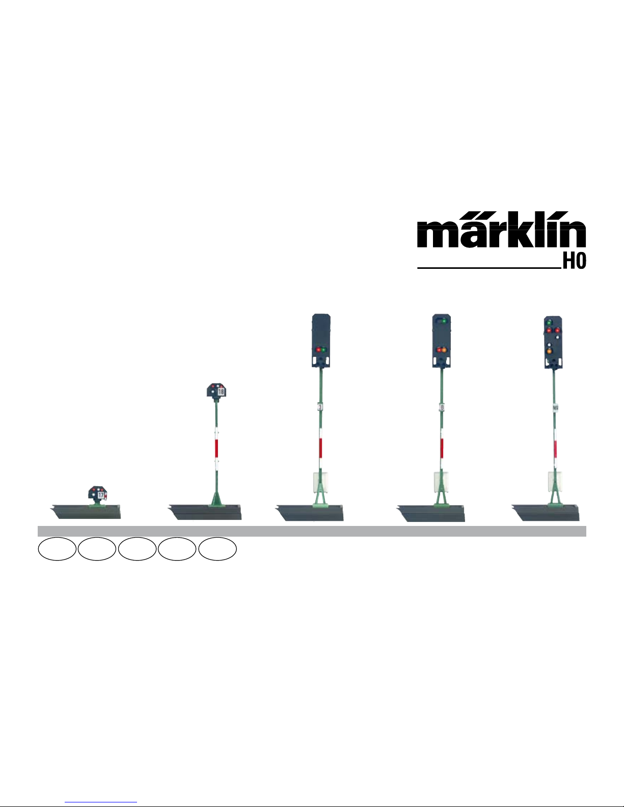
ThissignalisforinstallationonH0digitalmodelrailroadlayouts.
• Thissignalmayonlybeusedforanalogoperationwiththe
72760controlbox.
• Useonlyinenclosedareas.
Contents as Delivered
1 Signal
1 Decoder with mounting plate
1 Cable with plug, 2-conductor, red and brown
1 Cable with plug, 3-conductor, red and red
1 white and violet wires with 2-pin plugs for plugs
1 Cable with plug, 3-conductor, violet, red-green, red-braun
1 foundation piece of C Track with a cover
1 K Track base with a cover
1 grade wedge
1 cover for below-baseboard installation
1 screw 2 x 10 mm
2screws2.5x20mm
4 Insulator sleeves (red) for C track (1 sprue)
2 Center conductor insulators (gray) for K Track
1 Center conductor connector for K Track
1 Set of decals for identification
Installation instructions
Warranty card
Safety Notes
• IMPORTANT! The product has sharp edges and points due to
thewayitworks.
• Dowiringandinstallationworkonlywhenthereisnovoltage
present.Failuretoadheretothismaycauselife-threatening
currentandinjury.
• This signal is to be operated only with the permissible
voltage (seetechnicaldata).
Important Notes
• Theoperatinginstructionsareacomponentpartofthe
product and must therefore be kept in a safe place as well as
fortransferoftheproducttothirdparties.
• Thesignalmastsforthe76371/76372/76391/76393/76394
signalscannotbeusedwiththiselectroniccircuit(decoder).
• PleaseseeyourauthorizedMärklinspecialtydealerforrepairs.
• Disposingoftheproduct:www.maerklin.com/en/imprint.html
Technical Data
• Voltagesupply 16-20V
• Load ≤100 milliamps
• Loadatthetrackoutput max.2amps
• Electricalstrength max.40volts
Functions
• Capableofmulti-protocols:fx(MM),mfx*,andDCC
• ModeofoperationsetbymeansofDIPswitches
• AddressescanbesetbymeansofDIPswitches:
1-256 fx (MM) (Control Unit 6021)
1-320 fx (MM) (Central Station 6021x/Mobile Station 60653)
1-511 (DCC)
*mfxnotuntilCS2SoftwareVersion4.0(2ndquarterof2015)

10
•ProgrammableaddressesbymeansofCVs1-2,040 DCC
•CharacteristicscanbechangedbymeansofCVs
•Powersuppliedbymeansofthedigitalcurrentcircuit
Signal Installation
Thesignalmustbeprogrammedbeforeactuallyinstallingit.
The following work steps may be done only when there is no
voltage present:
SettingtheaddressandthemodeofoperationwiththeDIPswitches:
• SettingthemodeofoperationwithDIPSwitch10
Switch 10 off = fx (MM) / mfx
Switch 10 on = DCC
• fx(MM)/DCCSettingtheaddresswithDIPswitches(See
table starting on Page 18)
Please note: Always do settings with the DIP switches when
thereisnovoltagepresent.Thesignaldoesnotrecognizethe
currentswitchsettingsuntilthevoltageisturnedon.
Programming with the CS 2
fx (MM)
TheCVprogrammingmustbedoneontheprogrammingtrack.
Only one signal may be connected to the programming track at
a time.
ThefollowingCVscanbechangedinfx(MM):CV40,45,48and50.
Duringtheprogrammingprocedure,thesignallightwillblink.
During programming with the Central Station, by contrast the
signalisswitched.Aftertheendoftheprogrammingprocedure,
thesignalissetat“Go”.
An fx dummy locomotive with the address of the signal must be
enteredbeforeprogrammingwiththeMobileStation2.Activate
thesignalonce.Afterthat,changethedesiredCVsettingsand
switchthesignalonemoretime.
The procedure for programming with the 6021 Control Unit can
befoundatwww.maerklin.de->Tools&Downloads->Tech-
nischeInformationen.
Please see the operating instructions for the control devices in
questionforprogrammingwithotherdevices.
DCC
CVprogrammingmustbedoneontheprogrammingtrack.Only
one signal may be connected to the programming track at a
time.
The signal will blink for monitoring purposes during the data
transfer.
Please see the operating instructions for the control devices in
questionforprogrammingwithotherdevices.
CV for fx (MM) and DCC
Withfx(MM)theaddresscanbesetonlywiththeDIPswitches.
Thevaluesinparenthesesarefactorydefaultsettings.
CV Meaning Values
1 Address 1 - 255 1-255 (1) only DCC
9 Addresses 256 - 2040 0-7 (0) only DCC
33 Numer of output
addresses read only DCC

11
CV Meaning Values
40
PoM*
Meaning Lighting 0 - 15 (15) 0 light off
Dimming 0-15,
whereby 15 = 100%
brightness
45
PoM*
Home signal
76471/76472
76491
76493
76494
1
2
3
4
Track block / yard signal
Block signal
Entry signal
Exit signal
48
PoM*
Switching duration
LED on/off 0 - 3 0 = 0 seconds
1=0.175seconds
2=0.35seconds
3=0.5seconds
50 Cross fading behavior 0 - 3 0 = simultaneously
1 = one after the other
2 = one after the other
0.1sec.pause
3 = one after the other
0.5sec.pause
*PoMprogrammingcanbedoneonthemaintrackaslongasit
issupportedbythecontroldevice.
Setting and Calculating Addresses Greater than 255 (DCC):
Example:Address1044->1044:256=4.078125.Thevaluebefore
thedecimalpoint(4)isenteredinCV9.Thevalueafterthe
decimalpoint(0.078125)ismultipliedby2560.078125x256=20.
Thecalculatedvalueof20mustbeenteredinCV1.
Disposing
Products marked with a trash container with a line
through it may not be disposed of at the end of
theirusefullifeinthenormalhouseholdtrash.They
must be taken to a collection point for the
recyclingofelectricalandelectronicdevices.
There is a symbol on the product, the operating
instructions,orthepackagingtothiseffect.The
materials in these items can be used again according to this
marking.Byreusingolddevices,materiallyrecycling,or
recycling in some other form of old devices such as these you
make an important contribution to the protection of our
environment.Pleaseaskyourcity,town,community,orcounty
authoritiesforthelocationoftheappropriatedisposalsite.
Warranty
The warranty card included with this product specifies the
warrantyconditions.
• PleasecontactyourauthorizedMärklindealerforrepairsor
contact:
Gebr.Märklin&Cie.GmbH
Reparaturservice
StuttgarterStr.55-57
73033 Göppingen
Germany
:+497161608222
E-Mail:[email protected]

12
Utilisation conforme
•Lesignalestconçupourêtremontésurdescircuitsferrovi-
airesminiaturesnumériquesH0.
•Lesignalnedoitêtreutiliséenmodeanaloguequ’avecun
pupitredecommande72760.
•Nedoitêtreutiliséquedansunepiècefermée.
Livraison
1 signal
1 Décodeur avec plaque support
1 câble avec prise bipolaire, rouge et marron
1 câble avec prise tripolaire, rouge et rouge
1 câble avec connecteurs 2 pôles blanc et violet
1 câble avec prise tripolaire, violet, rouge-brun, rouge-vert
1 socle voie C avec cache
1 socle voie K avec cache
1 cale pour rampe
1 cache pour montage sous le plateau
1 vis 2 x 10mm
2 vis 2,5 x 20mm
4isolations(rouge)voieC(1piècemouléeparinjection)
2 isolations pour conducteur central (gris) voie K
1 connecteur pour conducteur central voie K
1 image à coulisser pour la signalisation
Instructions de montage
Certificat de garantie
Consignes de sécurité
• ATTENTION ! Le matériel comporte des bords coupants et
despointes.
• Effectuerlestravauxdecâblageetdemontageuniquement
lorsquelecircuitesthorstension.Danslecascontraire,vous
risquezdevousélectrocuteretdevousblesser.
• Utiliser le signal uniquement avec la tension autorisée (cf.
caractéristiquestechniques).
Consignes importantes
• Lemoded’emploifaitpartieintégranteduproduit.Vousdevez
donclaconserveretlatransmettreavecleproduit.
• Lesmâtsdessignaux76371/76372/76391/76393/76394ne sont
pas compatiblesaveccemoduleélectronique(décodeur).
• Pourlestravauxderéparation,veuillezvousadresseràvotre
revendeurMärklin.
• Élimination:www.maerklin.com/en/imprint.html
Caractéristiques techniques
• D‘alimentation 16-20V
• Charge ≤100 mA
• Chargesortievoie max.2A
• Rigiditédiélectrique max.40V
Fonctions
• Multiprotocole:fx(MM),mfx*etDCC
• Réglagedumodedefonctionnementaumoyend’uninterrup-
teur DIP
• Adressesréglablesaumoyendel’interrupteurDIP:
1-256 fx (MM) (Control Unit 6021)
1-320 fx (MM) (Central Station 6021x/Mobile Station 60653)
1-511 (DCC)
• AdressesprogrammablesviaCV
1-2 040 DCC
• ModicationdespropriétésviaCV
• Alimentationélectriqueviacircuitélectriquenumérique
*mfxàpartirdelaversionlogicielleCS24.0(2etrimestre2015)

13
Montage du signal
Avant le montage à proprement parler, vous devez programmer
lesignal.
Vous réaliserez les étapes suivantes uniquement lorsque le
circuit est hors tension :
Réglage de l’adresse et du mode de fonctionnement via
l’interrupteurDIP:
• Réglagedumodedefonctionnementaumoyend’uninterrup-
teur DIP 10
Interrupteur 10 off = fx (MM) / mfx
Interrupteur 10 on = DCC
• fx(MM)/DCCRéglagedel’adressevial’interrupteurDIP
(tableau à partir de la page 18)
Attention : Effectuer les réglages via l’interrupteur DIP unique-
menthorstension.Lesignalreconnaitlespositionsducommuta-
teurdèsl’activationdelatension.
Programmation avec CS 2
fx (MM)
La programmation CV doit se faire au niveau de la voie de
programmation.Vousne devez brancher qu’un seul signal sur la
voiedeprogrammation.
VouspouvezmodierlesCVsuivantdansfx(MM):CV40,45,
48et50.
Pendant la programmation, la lampe du signal clignote, et, in-
dépendamment de cela, le signal est couplé à la Central Station
pendantlaprogrammation.Unefoislaprocéduredeprogram-
mationterminée,lesignalestmissur«circulation».
Avant la programmation avec la Mobile Station 2, une loco-
motivefacticefxdoitavoirétécrééeavecl’adressedusignal.
Actionnezunefoislesignal,puisaccédezauxparamètresCV
souhaités,modiez-lesetcommutezànouveaulesignal.
Vous trouverez la procédure de programmation au moyen de
laControlUnit6021àlapagewww.maerklin.de->Tools&Down-
loads->TechnischeInformationen(www.marklin.fr/fr/produits/
outils/base_donnees_produits.html)
Pour la programmation avec d’autres appareils, veuillez
consulter les modes d’emploi des pupitres de commande
correspondant.
DCC
La programmation CV doit se faire au niveau de la voie de
programmation.nedevezbrancherqu’un seul signal sur la voie
deprogrammation.
Pendant la transmission des données, le signal clignote pour
contrôle.
Pour la programmation avec d’autres appareils, veuillez
consulter les modes d’emploi des pupitres de commande
correspondant.
CV pour fx (MM) et DCC
Dans fx (MM), vous pouvez configurer l’adresse uniquement
vial’interrupteurDIP.Lesvaleursentreparenthèsessontles
paramètresd’usine.
CV Éclairage Valeur
1 Adresse 1 - 255 1-255 (1) uniquement DCC
9 Adresses 256 - 2040 0-7 (0) uniquement DCC

14
CV Éclairage Valeur
33 Nombre d’adresses de
départ —Lire uniquement
40
PoM*
Éclairage 0 - 15
(15)
0lumièreéteinte
variateur 0-15,
15 = 100% de luminosité
45
PoM*
Signald’exécution:
76471/76472
76491
76493
76494
1
2
3
4
Signal de blocage de
la voie
Signal de block
Signal d’entrée
Signal de sortie
48
PoM*
Temps de commutation
LED allumée/éteinte 0 - 3
0 =0s
1 = 0,175s
2 = 0,35s
3 = 0,5s
50 Passage d’une indication
à l’autre
0 - 3
0 = simultanément
1 = successivement
2 = successivement
avec pause 0,1s
3 = successivement
avec pause 0,5s
*VouspouvezeffectuerlaprogrammationPoM,sielleestprise
enchargeparlepupitredecommande,surlavoieprincipale.
Réglage et calcul des adresses supérieures à 255 (DCC):Parex.
adresse1044->1044:256=4,078125.Vousdevezreporterlavaleur
avantlavirgule(4)dansCV9.Multipliezlavaleuraprèslavirgule
(0,078125)par2560,078125x256=20.Reportezlavaleurcalculée
20dansCV1.
Elimination
Indications relatives à la protection de l’environne-
ment:Lesproduitsmarquésdusignereprésentant
une poubelle barrée ne peuvent être éliminés en fin
devievialesorduresménagèresnormales,mais
doivent être remis à un centre de collecte pour le
recyclagedesappareilsélectriquesetélectroniques.
Le symbole figurant sur le produit lui-même, la notice
d’utilisationoul’emballagel’indique.Lesmatériauxsontrecyclables
selonleurmarquage.Aveclerecyclage,larécupérationdes
matériaux ou autres formes de valorisation de vieux appareils, vous
contribuezsensiblementàlaprotectiondenotreenvironnement.
Renseignez-vousauprèsdevotremunicipalitésurlescentres
compétentspourletraitementdesdéchets.
Garantie
Garantie légale et garantie contractuelle conformément au bon
degarantieci-joint.
• Pourtouteréparation,veuillezvousadresseràvotre
détaillant spécialisé Märklin ou à
Gebr.Märklin&Cie.GmbH
Reparaturservice
StuttgarterStr.55-57
73033 Göppingen / Allemagne
:+497161608222
E-mail:[email protected]

15
Beoogd gebruik
• HetseinisbestemdvoorhetinbouweninH0-modelbanen.
• Hetseinmaginanaloogbedrijfalleenincombinatiemethet
schakelkastje72760gebruiktworden.
• Hetmagalleeningeslotenruimtesgebruiktworden.
Leveringsomvang
1 Sein
1 Decoder met houderplaat
1 Kabel met stekker 2-polig rood en bruin
1 Kabel met stekker 3-polig rood en rood
1 Kabel met stekker 2 polig wit en violet
1 Kabel met stekker 3-polig violet, rood-groen, rood-bruin
1 Fundament C-rail met afdekking
1 Fundament K-rail met afdekking
1 Stijgingswig
1 Afdekking voor ondervloermontage
1 Schroef 2 x 10mm
2 Schroeven 2,5 x 20mm
4 Isolaties (rood) C-rail (1 gietstuk)
2 Middenrail isolaties (grijs) K-rail
1 Middenrail aansluiting K-rail
1 Transfer voor herkenning
Inbouwaanwijzing met sjabloon voor ondervloermontage
Garantiebewijs
Veiligheidsvoorschriften
• LETOP!Heeft vanwege de functionaliteit scherpe kanten en
punten.
• Bedradingenmontagewerkzaamhedenalleeninspanninglo-
zetoestanduitvoeren.Alsditnietinachtgenomenwordt
kunt u gevaarlijke stroomschokken krijgen met de daarmee
samenhangendeverwondingen.
• Hetseinalleenmetdetoegelatenspanning (zie technische
gegevens) gebruiken.
Belangrijke aanwijzingen
• Degebruiksaanwijzingiseenbestandsdeelvanhetproduct
en dient daarom bewaard en meegegeven worden met het
product.
• Deseinmastenvandeseinen76371/76372/76391/76394
kunnenmetdezeelektronica(decoder)nietgebruiktworden.
• VoorreparatieskuntuzichtotuwMärklindealerwenden.
• Verwijderingaanwijzing:www.maerklin.com/en/imprint.html
Technische gegevens
• Voedingsspanning 16-20V
• Belasting ≤100 mA
• Belastingrailuitgang max.2A
• Spanning max.40V
Functies
• Multi-protocolgeschiktvoor:fx(MM),mfx*enDCC
• Instellenvanhetbedrijfssysteemmetdipschakelaar
• Instelbareadressenmetdipschakelaars:
1-256 fx (MM) (Control Unit 6021)
1-320 fx (MM) (Central Station 6021x/ Mobile Station 60653)
1-511 (DCC)
*mfxpasvanafCS2softwareversie4.0(2dekwartaal2015)

16
• ProgrammeerbareadressenviaCV
1-2040 DCC
• VeranderenvandeeigenschappenviaCV
• Stroomvoorzieningviadigitalestroomkring
Sein inbouwen
Voor het inbouwen moet het sein eerst geprogrammeerd
worden.
De volgende werkzaamheden mogen alleen in spanningloze
toestand worden uitgevoerd:
•
Instellenvanhetadresenhetbedrijfssysteemmetdipschakelaar:
• Instellenvanhetbedrijfssysteemmetdipschakelaar10
Schakelaar 10 off = fx (MM) / mfx
Schakelaar 10 on = DCC
• fx(MM)/DCCinstellenvanhetadresmetdipschakelaar
(tabel zie pagina 18)
Let op: instelling met de dipschakelaar altijd in spanningloze
toestanduitvoeren.Hetseinherkentdeactueleinstellingpasna
hetinschakelenvandespanning.
Programmeren met CS2
fx (MM)
De CV programmering moet op het programmeerspoor worden
uitgevoerd.Ermagaltijd maar één sein op het programmeer-
spoorzijnaangesloten.
DevolgendeCV’skunnenbijfx(MM)veranderdworden:40,45,
48en50.
Tijdens het programmeren knippert het licht van het sein,
afwijkend daarvan wordt tijdens het programmeren met het
CentralStationhetseingeschakeld.Nahetafsluitenvanhet
programmerenwordthetseinindestand“veilig”gezet.
Voor het programmeren met het Mobile Station 2 moet een fx
dummie-locwordenaangemaaktmethetadresvanhetsein.Het
sein eenmaal bedienen, daarna naar gewenste CV instellingen
wisselen,wijzigenenafsluitendhetseinnogmaalsschakelen.
De werkwijze voor het programmeren met de Control Unit 6021
vindtuopwww.maerklin.de->Tools&Downloads->Tech-
nische Informationen
De wijze van programmering met andere apparaten vindt u in de
gebruiksaanwijzingvanhetdesbetreffendeapparaat.
DCC
De CV programmering moet op het programmeerspoor worden
uitgevoerd.Ermagaltijd maar één sein op het programmeer-
spoorzijnaangesloten.
Tijdens de dataoverdracht knippert de seinverlichting ter
controle.
De wijze van programmering met andere apparaten vindt u in de
gebruiksaanwijzingvanhetdesbetreffendeapparaat.
CV voor fx (MM) en DCC
Onder fx (MM) kan het adres alleen met de dipschakelaar
wordeningesteld.Dewaardentussenhaakjeszijndefabrieks-
instellingen.
CV Omschrijving Waarde
1 Adres 1 - 255 1-255 (1) alleen DCC
9 Adres 256 - 2040 0-7 (0) alleen DCC
33 Aantal uitgangadressen — alleen lezen/DCC

17
CV Omschrijving Waarde
40
PoM*
Verlichting 0 - 15 (15) 0=licht uit, dimmen
0-15 waarbij
15 = 100% helderheid
45
PoM*
Hoofdsein
76471/76472
76491
76493
76494
1
2
3
4
Spersein
Bloksein
Inrijdsein
Uitrijdsein
48
PoM*
Omschakeltijd
LED aan/uit 0 - 3
0=0s
1=0,175s
2=0,35s
3= 0,5s
50 Overvloei gedrag
0 - 3
0=gelijktijdig
1=na elkaar
2=na elkaar 0,1s pauze
3=na elkaar 0,5s pauze
*PoMprogrammerenkan,voorzoverhetbesturingsapparaatdit
ondersteund,ophethoofdspoorgebeuren.
Instellen en berekenen van de adressen groter dan 255 (DCC):
Bijv.adres144->1044:256=4,078125.Dewaardevoordekomma
(4)moetinCV9ingevoerdworden.Dewaardenadekomma
(0,078125)wordtmet256vermenigvuldigd,078125x256=20.De
berekendewaarde(20)wordtinCV1ingevoerd.
Afdanken
Milieu-informatie:producten,diemetde
doorgestreepte afvalcontainer zijn gemarkeerd,
mogen aan het einde van hun levensduur niet met
het normale huisvuil meegegeven worden, maar
moeten op een verzamelpunt voor de recycling van
elektrische en elektronische apparatuur afgegeven
worden.Hetsymboolophetproduct,opde
handleidingofopdeverpakkinggeeftditaan.Dematerialen
wordengerecycledinovereenstemmingmethunidenticatie.
Met het hergebruik van de grondstoffen of andere vormen van
het hergebruik van oude apparatuur levert u een belangrijke
bijdrageaandebeschermingvanonsmilieu.Neemcontactop
metuwgemeentevooreenbevoegdeplaatselijkeinzamelplaats.
Garantie
Waarborgengarantievolgensbijgevoegdgarantiebewijs.
• VoorreparatieskuntuzichwendentotuwMärklindealer
of tot
Gebr.Märklin&Cie.GmbH
Reparaturservice
StuttgarterStr.55-57
73033 Göppingen
Germany
Tel:+497161608222
E-Mail:[email protected]

18
10 ( 0/1 )
1 1 1 1 fx (MM)/DCC
2 1 2 2 fx (MM)/DCC
3 1 3 1 2 fx (MM)/DCC
4 1 4 3 fx (MM)/DCC
5 1 5 1 3 fx (MM)/DCC
6 1 6 2 3 fx (MM)/DCC
7 1 7 1 2 3 fx (MM)/DCC
8 1 8 4 fx (MM)/DCC
9 1 9 1 4 fx (MM)/DCC
10 1 10 2 4 fx (MM)/DCC
11 1 11 1 2 4 fx (MM)/DCC
12 1 12 3 4 fx (MM)/DCC
13 1 13 1 3 4 fx (MM)/DCC
14 1 14 2 3 4 fx (MM)/DCC
15 1 15 1 2 3 4 fx (MM)/DCC
16 1 16 5 fx (MM)/DCC
17 2 1 1 5 fx (MM)/DCC
18 2 2 2 5 fx (MM)/DCC
19 2 3 1 2 5 fx (MM)/DCC
20 2 4 3 5 fx (MM)/DCC
21 2 5 1 3 5 fx (MM)/DCC
22 2 6 2 3 5 fx (MM)/DCC
23 2 7 1 2 3 5 fx (MM)/DCC
24 2 8 4 5 fx (MM)/DCC
25 2 9 1 4 5 fx (MM)/DCC
26 2 10 2 4 5 fx (MM)/DCC
keyboard
Betriebsart und Adressen einstellen
Setting the mode of operation and addresses
Définir le mode d’exploitation et les adresses
Bedrijfsmodus en adres instellen

19
10 ( 0/1 )
27 2 11 1 2 4 5 fx (MM)/DCC
28 2 12 3 4 5 fx (MM)/DCC
29 2 13 1 3 4 5 fx (MM)/DCC
30 2 14 2 3 4 5 fx (MM)/DCC
31 2 15 1 2 3 4 5 fx (MM)/DCC
32 2 16 6 fx (MM)/DCC
33 3 1 1 6 fx (MM)/DCC
34 3 2 2 6 fx (MM)/DCC
35 3 3 1 2 6 fx (MM)/DCC
36 3 4 3 6 fx (MM)/DCC
37 3 5 1 3 6 fx (MM)/DCC
38 3 6 2 3 6 fx (MM)/DCC
39 3 7 1 2 3 6 fx (MM)/DCC
40 3 8 4 6 fx (MM)/DCC
41 3 9 1 4 6 fx (MM)/DCC
42 3 10 2 4 6 fx (MM)/DCC
43 3 11 1 2 4 6 fx (MM)/DCC
44 3 12 3 4 6 fx (MM)/DCC
45 3 13 1 3 4 6 fx (MM)/DCC
46 3 14 2 3 4 6 fx (MM)/DCC
47 3 15 1 2 3 4 6 fx (MM)/DCC
48 3 16 5 6 fx (MM)/DCC
49 4 1 1 5 6 fx (MM)/DCC
50 4 2 2 5 6 fx (MM)/DCC
51 4 3 1 2 5 6 fx (MM)/DCC
keyboard
10 ( 0/1 )
52 4 4 3 5 6 fx (MM)/DCC
53 4 5 1 3 5 6 fx (MM)/DCC
54 4 6 2 3 5 6 fx (MM)/DCC
55 4 7 1 2 3 5 6 fx (MM)/DCC
56 4 8 4 5 6 fx (MM)/DCC
57 4 9 1 4 5 6 fx (MM)/DCC
58 4 10 2 4 5 6 fx (MM)/DCC
59 4 11 1 2 4 5 6 fx (MM)/DCC
60 4 12 3 4 5 6 fx (MM)/DCC
61 4 13 1 3 4 5 6 fx (MM)/DCC
62 4 14 2 3 4 5 6 fx (MM)/DCC
63 4 15 1 2 3 4 5 6 fx (MM)/DCC
64 4 16 7 fx (MM)/DCC
65 5 1 1 7 fx (MM)/DCC
66 5 2 2 7 fx (MM)/DCC
67 5 3 1 2 7 fx (MM)/DCC
68 5 4 3 7 fx (MM)/DCC
69 5 5 1 3 7 fx (MM)/DCC
70 5 6 2 3 7 fx (MM)/DCC
71 5 7 1 2 3 7 fx (MM)/DCC
72 5 8 4 7 fx (MM)/DCC
73 5 9 1 4 7 fx (MM)/DCC
74 5 10 2 4 7 fx (MM)/DCC
75 5 11 1 2 4 7 fx (MM)/DCC
76 5 12 3 4 7 fx (MM)/DCC
keyboard

20
10 ( 0/1 )
77 5 13 1 3 4 7 fx (MM)/DCC
78 5 14 2 3 4 7 fx (MM)/DCC
79 5 15 1 2 3 4 7 fx (MM)/DCC
80 5 16 5 7 fx (MM)/DCC
81 6 1 1 5 7 fx (MM)/DCC
82 6 2 2 5 7 fx (MM)/DCC
83 6 3 1 2 5 7 fx (MM)/DCC
84 6 4 3 5 7 fx (MM)/DCC
85 6 5 1 3 5 7 fx (MM)/DCC
86 6 6 2 3 5 7 fx (MM)/DCC
87 6 7 1 2 3 5 7 fx (MM)/DCC
88 6 8 4 5 7 fx (MM)/DCC
89 6 9 1 4 5 7 fx (MM)/DCC
90 6 10 2 4 5 7 fx (MM)/DCC
91 6 11 1 2 4 5 7 fx (MM)/DCC
92 6 12 3 4 5 7 fx (MM)/DCC
93 6 13 1 3 4 5 7 fx (MM)/DCC
94 6 14 2 3 4 5 7 fx (MM)/DCC
95 6 15 1 2 3 4 5 7 fx (MM)/DCC
96 6 16 6 7 fx (MM)/DCC
97 7 1 1 6 7 fx (MM)/DCC
98 7 2 2 6 7 fx (MM)/DCC
99 7 3 1 2 6 7 fx (MM)/DCC
100 7 4 3 6 7 fx (MM)/DCC
101 7 5 1 3 6 7 fx (MM)/DCC
keyboard
10 ( 0/1 )
102 7 6 2 3 6 7 fx (MM)/DCC
103 7 7 1 2 3 6 7 fx (MM)/DCC
104 7 8 4 6 7 fx (MM)/DCC
105 7 9 1 4 6 7 fx (MM)/DCC
106 7 10 2 4 6 7 fx (MM)/DCC
107 7 11 1 2 4 6 7 fx (MM)/DCC
108 7 12 3 4 6 7 fx (MM)/DCC
109 7 13 1 3 4 6 7 fx (MM)/DCC
110 7 14 2 3 4 6 7 fx (MM)/DCC
111 7 15 1 2 3 4 6 7 fx (MM)/DCC
112 7 16 5 6 7 fx (MM)/DCC
113 8 1 1 5 6 7 fx (MM)/DCC
114 8 2 2 5 6 7 fx (MM)/DCC
115 8 3 1 2 5 6 7 fx (MM)/DCC
116 8 4 3 5 6 7 fx (MM)/DCC
117 8 5 1 3 5 6 7 fx (MM)/DCC
118 8 6 2 3 5 6 7 fx (MM)/DCC
119 8 7 1 2 3 5 6 7 fx (MM)/DCC
120 8 8 4 5 6 7 fx (MM)/DCC
121 8 9 1 4 5 6 7 fx (MM)/DCC
122 8 10 2 4 5 6 7 fx (MM)/DCC
123 8 11 1 2 4 5 6 7 fx (MM)/DCC
124 8 12 3 4 5 6 7 fx (MM)/DCC
125 8 13 1 3 4 5 6 7 fx (MM)/DCC
126 8 14 2 3 4 5 6 7 fx (MM)/DCC
127 8 15 1 2 3 4 5 6 7 fx (MM)/DCC
keyboard
This manual suits for next models
4
Table of contents
Other marklin Toy manuals

marklin
marklin 36426 User manual

marklin
marklin 37682 User manual

marklin
marklin 29342 User manual

marklin
marklin 36824 User manual

marklin
marklin 39402 User manual

marklin
marklin 37293 User manual

marklin
marklin 29450 User manual

marklin
marklin 29100 User manual

marklin
marklin 37175 User manual

marklin
marklin BR 86 29532 User manual

marklin
marklin 55248 User manual

marklin
marklin 37146 User manual

marklin
marklin BR 61 User manual

marklin
marklin T 299 DSB User manual

marklin
marklin 36501 User manual

marklin
marklin 37414 User manual

marklin
marklin Dampflok BR 99 4653 User manual

marklin
marklin 7294 User manual

marklin
marklin 37083 User manual

marklin
marklin 29481 User manual