Metrica BRAVO ROTATIVO H User manual

Ref. 60719BM
BRAVO
LASER
ROTATIVO H

2
MANUALE D’USO
CORPO PRINCIPALE
MODULO
LASER
MANIGLIA
FINESTRE
USCITA
LASER
PANNELLO
DI CONTROLLO
REGOLAZIONE
DELLA SCANSIONE
LED ALIMENTAZIONE
INTERRUTTORE
ACCESO/SPENTO
RICEVENTE A INFRAROSSI
REGOLAZIONE VELOCITA’
DI ROTAZIONE
ADS LED
INTERRUTTORE TILT
LED MANUALE
PANNELLO DI CONTROLLO
Funzioni del pannello:
1. ON/OFF: Pulsante per accensione e spegnimento.
2. Led di alimentazione e modalità: quando il led è acceso, lo
strumento è ON, quando il led è spentolo strumento è OFF
3. Led di alimentazione e modalità: quando il led è illuminato, lo
strumento si sta livellando manualmente. Quando il led lam-
peggia lo strumento è in allarme. (La pendenza dello strumen-
to è fuori dalla portata massima consentita).
4. Pulsante TILT: avvisa l’utente per un disallineamento del dispo-
sitivo
5. LED TILT: quando il led lampeggia lentamente, la funzione è
inserita, Quando il led lampeggia rapidamente, indica che il
laser è stato scosso e non si livellerà fino a nuova accensione.
6. Pulsante regolazione della velocità. La velocità di rotazione
include 5 valori: 0-60-120-300-600-0 g/m
7. Modalità scansione: la modalità di scansione prevede 5 angoli:
0°-10°-45°-90°-180°
Avviso: utilizzando il telecomando si possono avere ulteriori
altre funzioni.
Installazione della batteria
1. Le batterie ricaricabili Ni-MH 4X1.2V (ricaricabili esternamen-
te con apposito caricatore incluso) possono essere utilizzate
nello strumento.

3
2. Rimuovere il coperchio dell’alloggiamento della batteria nella
parte posteriore dello strumento.
3. Inserire le batterie nella custodia secondo la polarità giusta.
4. Appoggiare il coperchio sulla scatola, quindi serrare tutte le viti.
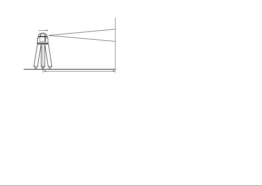
Posizionamento dello strumento
Appoggiare lo strumento sul treppiede o su una superficie pia-
na stabile o uniforme mantenere la pendenza dello strumento
nell’intervallo da -5 ° a + 5 °.
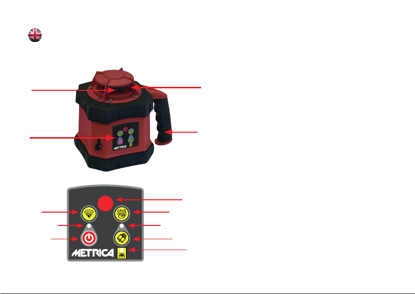
OPERAZIONI
Accensione
1. Premere il tasto ON/OFF per attivare lo strumento e il livella-
mento automatico. L’indicatore di alimentazione si illumina.
2. Premere nuovamente il tasto ON/OFF per spegnere lo stru-
mento. l’indicatore di alimentazione si spegne.
Livellamento
1. Premendo il tasto ON/OFF oltre all’accensione si attiva il livel-
lamento automatico che terminerà dopo la fine del lampeggio
del laser. Dopo il livellamento automatico, il modulo laser ruo-
terà a destra alla velocità di 600 giri/min.
2. Se lo strumento non è posizionato correttamente o la penden-
za dello strumento supera l’intervallo da -5° a +5 °, l’indica-
tore di modalità e il raggio laser lampeggeranno all’unisono.
Quindi posizionare il strumento correttamente.
Avviso: lo strumento si chiuderà automaticamente dopo al-
larme di cinque minuti.
ROTAZIONI
Rotazione continua
Premere il tasto “VELOCITA’ DI ROTAZIONE” per controllare la ve-
locità del modulo laser. Se si preme ripetutamente il tasto, della
velocità di rotazione, la velocità del modulo laser cambierà come
segue: 0-60-120-300-600-0 giri/min.
Passo a passo
Con il dispositivo acceso ed a una velocità di o giri/min. (sul te-
lecomando) premere il tasto rotazione a destra, il modulo laser
si sposterà in senso orario. Poi se si preme il tasto rotazione a
sinistra, il modulo laser si sposterà Antiorario.
Scansione
1.Premendo il tasto della scansione; il modulo laser eseguirà la
scansione direzionale. Se si preme ripetutamente il tasto, l’an-
golo di scansione del modulo laser cambierà continuamente
come segue: 0 ° - 10 ° - 45 ° - 90 ° - 180 ° - 0 °.
2.(sul telecomando) Premere il tasto rotazione a sinistra o il tasto
rotazione a destra su cambia la direzione di scansione.
REGOLAZIONE SLOPE (CON TELCOMANDO)
A dispozitivo acceso, e la rotazione a 0 giri/min., Premere il tasto
Manuale/Automatico quando l’indicatore della modalità si illumi-
na, lo strumento
entra nella modalità di livellamento manuale.

4
Pendenza dell’asse X.
Puntare il raggio X1 nella direzione della pendenza richiesta per
regolare,come illustrato di seguito
Y2
Y1
X2 X1
Premere il tasto o per spostare il raggio laser verso
l’alto o verso il basso.
Pendenza dell’asse Y.
Puntare il raggio Y1 nella direzione della pendenza richiesta per
regolare.
Premere il tasto o per spostare il raggio laser verso l’alto
o verso il basso.
Avvertenze: premendo nuovamente il tasto Manuale/Auto-
matico l’indicatore si spegnerà e lo strumento entrerà in
modalità livellamento automatico.
TELECOMANDO
Il telecomando dello strumento adotta la tecnica
a infrarossi, pertanto puntare per il funzionamen-
to, puntare il telecomando verso lo strumento (di-
stanza disponibile: interna: 30 M; esterno: 20 M).
Il pannello di telecontrollo include 9 pulsanti. E
un led per confermare che il segnale operativo
è stato inviato.
Funzioni dal telecomando
1. Velocita di rotazione
2. Scansione
3. Senso di rotazione passo a passo
4. Livellamento Manuale / Automatico
5. Regolazione della pendenza: in metodo manuale
CONTROLLO LIVELLAMENTO
Posizionare lo strumento nel punto di 50 m davanti al muro per
marcare il punto h1 sul il muro, come illustrato di seguito:
Telecomando

5
X1 - raggio
h1
h2
X1
X2 - raggio
50 m (approsimativamente)
Accendere lo strumento, livellarlo automaticamente e portarlo ad
una rotazione di 0 giri al minuto.
Marcare il punto h1 del raggio X1 sulla parete
Allentare la vite del treppiede, quindi girare lo strumento di 180 °
per marcare il punto h2 del raggio X2 sulla parete.
Se il valore D tra h1 e h2 è inferiore a 10 mm lo strumento è
in tolleranza.
Controllare il raggio a Y allo stesso modo.

6
INFORMAZIONI TECNICHE
Precisione di livellamento ± 3mm/30m
Campo di autolivellamento ± 5º
Campo di lavoro 400 m (utilizzando il rilevatore laser)
Velocità di rotazione 0, 60, 120, 300, 600 giri/min
Scansione 0º, 10 º, 45 º, 90 º, 180 º
Intervallo di regolazione pendenza ± 5º (bidirezionale)
Tipo laser 635nm
Distanza di controllo remoto Circa 20m
Temperatura di lavoro 10 ° C / 45 ° C (14ºF / 113ºF)
Alimentatore CC 4,8-6 V (4 sezioni di batterie NI-MH o 4 sezioni di batterie ricaricabili NI-MH)
Ore in uso continuo Circa 8 ore
Impermeabilità IP 54
Dimensione 120 (L) × 120 (W) × 150 (H) mm
Peso 1,2 kg

7
OPERATING MANUAL
MAIN BODY
LASER MODULE
HANDLE
WINDOWS OF BEAM
KEYBOARDS
SCANNER
LED
ON/OFF
INFRARED RECEIVER
VELOCITIES
TILT LED
TILT FUNCTION
MANUAL / AUTOMATIC
KEYBOARD FUNCTIONS
1. ON/OFF: Control of the power state.
2. Power indicator: When it is lit, the unit starts.
3. Mode indicator: When it is lit, the instrument levels manually. If
it flashes, it remains in alarm standby mode (the instrument’s
inclination is outside the levelling range).
4.Tilt function:warns the user of a misalignment of the instrument.
5. Tilt function LED: if the LED flashes slowly, it is in tilt mode.
When the LED flashes rapidly, the instrument stops leveling.
6. Speeds: there are 5 to choose from: 0-60-120-300-600-0 rpm.
7. Scanner: the scanning angle is 5 steps: 0-10°-45°-90°-180°.
Note: You can use the remote control to access additional
functions.
OPERATION
Inserting the battery
1. 4×C size Ni-MH batteries can be used in the unit.
2. Remove the cover of the battery compartment on the bottom
of the unit.
3. Insert the batteries into the housing according to the right
electrode.
4. Place the cover on the battery compartment and tighten all
screws.
Positioning the unit
Place the unit on a tripod or stable flat surface or even hang it on

8
the wall. Place the unit in an upright position and keep the inclina-
tion of the instrument within the range of -5° to +5°.
OPERATION
Power
1. Press the ON/OFF button to activate the automatic levelling
function, the power indicator (Led) will light. 2.
2. When the power indicator (Led) is lit, it indicates that the
voltage of the batteries is insufficient. Then the rechargeable
batteries must be charged.
3. Press the ON/OFF button again to turn off the unit, the power
indicator goes out.
Levelling
Press the ON/OFF button to start automatic levelling, the laser
beam flashes. After automatic levelling, the laser module rotates
to the right at a speed of 600 rpm. 2. When the instrument is in
operation, the laser beam flashes.
If the instrument is improperly positioned or the inclination of the
instrument exceeds the range of -5° to +5°, the mode indicator
and the laser beam will flash simultaneously. Re-position the in-
strument within the self-levelling range.
Note: The unit turns off automatically after five minutes of
alarm.
ROTATION
Continuous rotation
Press the speed button to control the rotation speed of the laser
module. By repeatedly pressing the key, the speed of the laser
module changes continuously as follows: 0-60-120-300-600-
600-0 rpm.
Step Turning
Set the speed to 0 rpm, the laser module stops. Press the key
The laser module rotates clockwise. If you press the left turn but-
ton, the laser module moves counterclockwise.
Scanning
1. Press the scanning button; the laser module scans directional-
ly. If you press the button repeatedly, the scanning angle of the
laser module changes continuously as follows: 0°- 10°- 45°-
90°- 180°- 0°.
1. Press the Left Rotate key or the Right Rotate key to change the
scan direction.
TILT ADJUSTMENT (WITH REMOTE CONTROL)
When the unit is set upright to scan horizontally, the tilt of the
X-axis and Y-axis can be adjusted. Press the Manual/Automatic
button when the mode indicator is lit and the unit switches to the
manual leveling mode.

9
Inclination of the X axis
Align the X1 beam with the direction of the tilt required for
adjustment, as shown below:
Y2
Y1
X2 X1
Press the buttons or to move the laser beam up or
down.
Inclination of the Y-axis
Align the Y1 beam with the direction of the tilt required for
adjustment.
Press the keys or buttons to move the laser beam up
or down.
Notes: Press the Manual/Automatic button again when the
mode indicator goes off, the instrument switches to the au-
tomatic levelling mode.
REMOTE CONTROL
The remote control of the device transmits via
infrared technology.
Point the opening of the infrared beam at the la-
ser device (as shown below) to use the remote
control (distance: inside: 30 m; outside: 20 m).
The keyboard has 9 keys; the display on the unit
flashes to indicate that the operating signal has
been sent after pressing any key.
Remote control functions:
1. Rotation: Operating method referring to SPINNING
2. Scanner: Operating method referring to Directional scan-
ning
3. Inclination adjustment: Operating method referring to SLOPE
ADJUSTMENT
ACCURACY CHECK
Place the device 50 m away from a wall, then align the device in
direction X1 (see drawing):
Remote control

10
X1 - beam
h1
h2
X1
X2 - beam
50 m (approximately)
After putting the device into operation, measure h1. Loosen the
screw on the tripod and turn the device by 180 °; now measure
h2 on the wall. The value D, difference between h1 and h2, must
be less than 10 mm. Measure the Y-axis in the same way.
D-value between h1 and h2 ought to be less than 10mm.
Check the Y-beam in the same way.

11
TECHNICAL FEATURES
Horizontal levelling accuracy ± 3mm/30m
Self-levelling range ±5º
Measuring range Diameter: 400m (with laser receiver)
Rotation speeds 0, 60, 120, 300 and 600 rpm.
Scanner angle 0°, 45 °, 90 °, 180 °
Tilt adjustment range ±5º (bidirectional)
Laser type Wavelength: 635nm
Remote control distance approx. 20m
Operating temperature 10° - 45° (14ºF - 113ºF)
Power supply DC 4,8-6V (4 NI-MH batteries, normal or rechargeable)
Autonomy approx. 8 hours
Protection class IP 54
Dimensions 120(L) ×120(W) ×150(H) mm
Weight 1,2kg

12
MODE D’EMPLOI
CORPS PRINCIPAL
MODULE LASER
POIGNÉE
FENÊTRE DU
RAYON LASER
CLAVIER
SCANNER
LED
MARCHE/ARRÊT
RÉCEPTEUR INFRAROUGE
VITESSES
LED DU TILT
FONCTION D’INCLINAISON
MANUEL/AUTOMATIQUE
CLAVIER
Fonctions du clavier
1. ON/OFF : Contrôle de l’état de l’appareil.
2. Indicateur de puissance : lorsqu’il est allumé, l’appareil
démarre.
3. Indicateur de mode : lorsqu’il est allumé, l’appareil se met à
niveau manuellement. S’il clignote, il reste en mode veille d’a-
larme (l’inclinaison de l’instrument est en dehors de la plage
de nivellement).
4. Fonction d’inclinaison : avertit l’utilisateur d’un désalignement
de l’appareil.
5. LED de la fonction d’inclinaison : si la LED clignote lentement,
le laser est en mode inclinaison. Lorsque la LED clignote ra-
pidement, l’instrument est en alarme (l’inclinaison est hors
plage d’auto-nivellement).
6. Vitesses : il y a un choix de 5 : 0-60-120-120-300-600-600-0
tr/min.
7. Scanner: l’angle de balayage comprend 5 étapes : 0-10°-45°-
90°-180°.
Remarque: Vous pouvez utiliser la télécommande pour appe-
ler des fonctions supplémentaires.
PRÉPARATION
Mise en place de la batterie
1. Quatre piles rechargeables Ni-MH C peuvent être utilisées
dans l’instrument.

13
2. Retirez le couvercle du compartiment à piles situé sous l’ap-
pareil.
3. Insérez les piles dans le boîtier selon l’électrode de droite.
4. Placez le couvercle sur le compartiment des piles et serrez
toutes les vis.
Positionnement de l’appareil
Placez l’appareil sur un trépied ou une surface plane et stable ou
accrochez-le au mur. Placez l’appareil à la verticale et maintenez
l’inclinaison de l’instrument dans la plage de -5° à +5°.
Utilisation
1. Appuyez sur le bouton ON/OFF pour démarrer le nivellement
automatique, le voyant d’alimentation (Led) s’allume.
2. Lorsque le voyant d’alimentation (Led) est allumé, cela indique
que la tension de la batterie est insuffisante. Les piles rechar-
geables doivent être rechargées.
3. Appuyez de nouveau sur le bouton ON/OFF pour éteindre l’ap-
pareil, l’indicateur d’alimentation s’éteint.
Niveler
1. Appuyez sur la touche ON/OFF pour lancer le nivellement au-
tomatique, le faisceau laser clignote. Après le nivellement au-
tomatique, le module laser tourne vers la droite à une vitesse
de 600 tr/min.
2. Si l’appareil n’est pas correctement installé ou si l’inclinaison
de l’appareil dépasse la plage d’auto-nivellement de -5° à
+5°, l’indicateur de mode et le faisceau laser clignotent simul-
tanément. Replacer l’appareil dans la plage de mise à niveau
automatique.
Remarque: l’appareil s’éteint automatiquement après cinq
minutes d’alarme.
ROTATION
Rotation continue
Appuyez sur le bouton de vitesse pour contrôler la vitesse de ro-
tation du module laser. En appuyant plusieurs fois sur la touche,
la vitesse du module laser change continuellement comme suit :
0-60-120-300-300-600-600-600-0 tr/min.
Rotation pas-à-pas
Régler la vitesse à 0 tr/min, le module laser s’arrête. Appuyer sur
la touche ….. Le module laser tourne dans le sens des aiguilles
d’une montre. Si vous appuyez sur le bouton de rotation gauche,
le module laser se déplace dans le sens antihoraire.
Scanner
1. Appuyez sur la touche de balayage (scanner) ; le module laser
effectue un balayage directionnel. Si vous appuyez plusieurs
fois sur la touche, l’angle de balayage du module laser change
continuellement comme suit: 0°- 10°- 45°- 90°- 180°- 0°.

14
2. Appuyez sur la touche Rotation gauche ou Rotation droite
pour changer le sens de balayage.
RÉGLAGE DE L’INCLINAISON (AVEC TÉLÉCOMMANDE)
Lorsque l’appareil est placé verticalement pour numériser ho-
rizontalement, l’inclinaison de l’axe X et de l’axe Y peut être
réglée. Appuyez sur la touche Manuel/Automatique lorsque le
voyant de mode est allumé et que l’instrument passe en mode
de nivellement manuel.
Inclinaison de l’axe X
Alignez le rayon X1 avec la direction de l’inclinaison requise pour
le réglage, comme indiqué ci-dessous :
Y2
Y1
X2 X1
Appuyer sur la touche or pour déplacer le faisceau
laser vers le haut ou vers le bas.
Inclinaison de l’axe Y
Alignez le rayon Y1 avec la direction de l’inclinaison requise pour
le réglage.
Appuyer sur les touches or pour déplacer le faisceau laser
vers le haut ou vers le bas.
Remarques: lorsque l’indicateur de mode s’éteint, appuyez à
nouveau sur la touche Manuel/Automatique, l’appareil pas-
se en mode de nivellement automatique.
TÉLÉCOMMANDE
La télécommande de l’appareil transmet en
technologie infrarouge.
Dirigez l’ouverture du faisceau infrarouge vers
l’appareil laser (comme indiqué ci-dessous) pour
utiliser la télécommande (distance : intérieur :
30 m ; extérieur : 20 m). Le clavier contient 9
touches ; l’affichage de l’appareil clignote pour
indiquer que le signal de fonctionnement a été
envoyé après qu’une touche a été actionnée.
Fonctions de la télécommande:
1. Rotation: Operating method referring to SPINNING
2. Rotation pas-à-pas: Operating method referring to Directio-
nal scanning
3. Réglage de l’inclinaison: Operating method referring to SLO-
PE ADJUSTMENT
Télécommande

15
VÉRIFICATION DE PRÉCISION
Placez l’appareil à 50 m d’un mur, puis alignez l’appareil dans la
direction X1 (voir dessin):
X1 - rayon
h1
h2
X1
X2 - rayon
50 m (approximativement)
Après la mise en service de l’appareil, mesurer h1. Desserrer la
vis du trépied et tourner l’appareil de 180° ; maintenant mesurer
h2 sur le mur. La valeur D, différence entre h1 et h2, doit être
inférieure à 10 mm. Effectuer la mesure de l’axe Y de la même
manière.
La valeur D entre h1 et h2 doit être inférieure à 10 mm.
Vérifier la poutre en Y de la même manière.

16
CARACTÉRISTIQUES TECHNIQUES
Précision du nivellement horizontal ± 3mm/30m
Plage d’auto-nivellement ±5º
Plage de mesure Diamètre : 400m (avec récepteur laser)
Vitesses de rotation 0, 60, 120, 300 et 600 tr/min.
Angles de balayage (scanner) 0°, 45 °, 90 °, 180 °.
Plage de réglage de l’inclinaison ±5º (bidirectionnelle)
Type de laser 635 nm
Distance de télécommande env. 20m
Température de fonctionnement -10° - 45° (14ºF - 113ºF)
Alimentation DC 4,8-6V (4 piles NI-MH, normales ou rechargeables)
Autonomie env. 8 heures
Indice de protection IP 54
Dimensions 120 (L) ×120 (l) ×150 (H) mm
Poids 1,2kg

17
BEDIENUNGSANLEITUNG
HAUPTTEIL
LASERMODUL
GRIFF
FENSTER DES
STRAHLS
TASTATUR
SCANNER
LED
EIN/AUS
INFRAROTEMPFÄNGER
GESCHWINDIGKEITE
TILT-LED
TILT-FUNKTION
MANUELL/AUTOMATISCH
TASTATUR
Funktionen der Tastatur
1. EIN/AUS: Steuerung des Leistungszustands.
2. Stromanzeige: Wenn sie leuchtet, startet das Gerät.
3. Modusanzeige:Wenn sie leuchtet, nivelliert das Gerät manuell.
Wenn sie blinkt, bleibt es in Alarmbereitschaft (die Neigung
des Instruments ist außerhalb des Nivellierbereichs).
4. Tilt-Funktion: Warnt den Benutzer vor einer Fehlausrichtung
des Geräts.
5. LED der Tilt-Funktion: wenn die Led langsam blinkt, befindet
es sich im Tilt-Modus. Wenn die Led schnell blinkt, ist das
Gerät im Alarmmodus (außerhalb des Selbstnivellierberei-
ches).
6. Geschwindigkeiten: es stehen 5 zur Wahl: 0-60-120-300-
600-0 U/min.
7. Scanner: der Abtastwinkel umfasst 5 Stufen: 0-10°-45°-90°-
180°.
Hinweis: Mit der Fernbedienung können Sie zusätzliche
Funktionen aufrufen.
BEDIENUNG
Einlegen der Batterie
1. Ni-MH-AkkusderGröße4×CkönnenimGerätverwendetwerden.
2. Entfernen Sie den Deckel des Batteriefachs an der Unterseite
des Gerätes.

18
3. Legen Sie die Batterien entsprechend der rechten Elektrode in
das Gehäuse ein.
4. Legen Sie den Deckel auf das Batteriefach und ziehen Sie alle
Schrauben an.
Positionieren des Geräts
Legen Sie das Gerät auf das Stativ oder eine stabile ebene Fläche
oder hängen Sie es sogar an die Wand. Stellen Sie das Gerät au-
frecht und halten Sie die Neigung des Instruments im Bereich
von -5° bis +5°.
BETRIEB
1. Drücken Sie die Taste EIN/AUS, um die automatische Nivellie-
rung in Betrieb zu nehmen, die Betriebsanzeige (Led) leuchtet.
2. Wenn die Betriebsanzeige (Led) leuchtet, zeigt sie an, dass die
Spannung der Batterien unzureichend ist. Dann müssen die
wiederaufladbaren Batterien aufgeladen werden.
3. Drücken Sie die Taste EIN/AUS erneut, um das Gerät auszu-
schalten, die Betriebsanzeige erlischt.
Nivellierung
1. Drücken Sie die Taste EIN/AUS, um die automatische Nivellie-
rung in Betrieb zu nehmen, der Laserstrahl blinkt. Nach dem
automatischen Nivellieren dreht sich das Lasermodul mit einer
Geschwindigkeit von 600 U/min nach rechts.
2. Wenn das Gerät unsachgemäß aufgestellt wird oder die Nei-
gung des Geräts den Bereich von -5° bis +5° überschreitet,
blinken die Modusanzeige und der Laserstrahl gleichzeitig.
Positionieren Sie das Gerät erneut innerhalb des Selbstnivel-
lierbereichs.
Hinweis: Das Gerät schaltet sich nach fünf Minuten Alarm
automatisch ab.
ROTATION
Kontinuierliche Rotation
Drücken Sie die Geschwindigkeitstaste, um die Rotationsge-
schwindigkeit des Lasermoduls zu steuern. Durch wiederholtes
Drücken der Taste ändert sich die Geschwindigkeit des Laser-
moduls kontinuierlich wie folgt: 0-60-120-300-600-600-0 U/min
Schrittdrehen
Stellen Sie die Geschwindigkeit auf 0 U/min, das Lasermodul
stoppt. Drücken Sie die Taste
der Rechtsdrehung, das Lasermodul dreht im Uhrzeigersinn.
Wenn Sie die Taste Linksdrehung drücken, bewegt sich das La-
sermodul gegen den Uhrzeigersinn.
Scanning
1. Drücken Sie die Scanning-Taste; das Lasermodul scannt
richtungsweisend. Wenn Sie die Taste wiederholt drücken, än-
dert sich der Scanning-Winkel des Lasermoduls kontinuierlich
wie folgt: 0°- 10°- 45°- 90°- 180°- 0°.

19
2. Drücken Sie die Taste Linksdrehung oder die Taste
Rechtsdrehung, um die Scan-Richtung zu ändern.
NEIGUNGSVERSTELLUNG (MIT FERNSTEUERUNG)
Wenn das Gerät aufrecht aufgestellt ist, um horizontal zu scan-
nen, kann die Neigung der X-Achse und der Y-Achse eingestellt
werden. Drücken Sie die Taste Manuell/Automatisch, wenn die
Modusanzeige leuchtet und das Gerät in den Modus der manuel-
len Nivellierung wechselt.
Neigung der X-Achse
Richten Sie den X1-Strahl auf die Richtung der zur Einstellung
erforderlichen Neigung aus, wie unten dargestellt:
Y2
Y1
X2 X1
Drücken Sie die Tasten oder um den Laserstrahl nach
oben oder unten zu bewegen.
Neigung der Y-Achse
Richten Sie den Y1-Strahl auf die Richtung der zur Einstellung
erforderlichen Neigung aus.
Drücken Sie die Tasten oder um den Laserstrahl nach
oben oder unten zu bewegen.
Notizen: Drücken Sie die Taste Manuell/Automatisch erneut,
wenn die Modusanzeige erlischt, das Gerät wechselt in den Mo-
dus der automatischen Nivellierung.
FERNBEDIENUNG
Die Fernbedienung des Gerätes überträgt per
Infrarottechnik.
Richten Sie die Öffnung des Infrarot-Strahls auf
das Lasergerät (wie unten dargestellt), um die
Fernbedienung zu nutzen (Entfernung: Innen: 30
m; Außen: 20 m). Die Tastatur beinhaltet 9 Ta-
sten; die Anzeige am Gerät blinkt, um anzuzei-
gen, dass das Betriebssignal nach Drücken einer
beliebigen Taste gesendet wurde.
Funktionen der Fernbedienung
1. Rotation: Operating method referring to SPINNING
2. Schrittdrehen: Operating method referring to Directional
scanning
3. Neigungsverstellung: Operating method referring to SLOPE
ADJUSTMENT
Fernbedienung

20
GENAUIGKEITSPRÜFUNG
Platzieren Sie das Gerät 50 m von einer Wand entfernt, dann
richten Sie das Gerät in Richtung X1 aus (s. Zeichnung):
X1 - Strahl
h1
h2
X1
X2 - Strahl
50 m (ungefähr)
Nach Inbetriebnahmen des Gerätes, messen Sie h1. Lösen Sie die
Schraube am Stativ und drehen Sie das Gerät um 180 °; messen
Sie nun h2 an der Wand. Der Wert D, Unterschied zwischen h1
und h2, muss geringer als 10 mm sein. Führen Sie die Messung
der Y-Achse genauso durch.
Der D-Wert zwischen h1 und h2 sollte kleiner als 10mm sein.
Überprüfen Sie den Y Strahl auf die gleiche Weise.
This manual suits for next models
1
Table of contents
Languages:
Other Metrica Measuring Instrument manuals

Metrica
Metrica CALIBRO IP 67 User manual

Metrica
Metrica 10080 User manual

Metrica
Metrica 60291 User manual

Metrica
Metrica BRAVO LASER ROTATIVO User manual

Metrica
Metrica 61530 User manual

Metrica
Metrica c80 User manual

Metrica
Metrica DIGIGRAD 29890 User manual

Metrica
Metrica 61345 User manual

Metrica
Metrica 61160 User manual

Metrica
Metrica H4 User manual