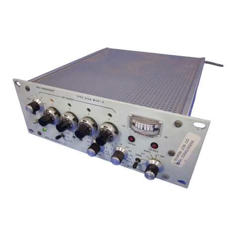
MKS 153D User manual

115714-P1
Rev D, 3/99
Instruction Manual
MKS Type 153D and 1253D
Throttle Valve
Controllers
Six Shattuck Road
Andover, MA 01810-2449
(800) 227-8766 or (978) 975-2350
Fax: (978) 975-0093
E-mail: mks@mksinst.com
Web site: http://www.mksinst.com

WARRANTY
Type 153D/1253D Equipment
MKS Instruments, Inc. (MKS) warrants that the equipment described above (th
e
“equipment”) manufactured by MKS shall be free from defects in materials and
workmanship for a period of one year from date of shipment and will for a period of tw
o
years from the date of shipment, correctly perform all date-related operations, including
without limitation accepting data entry, sequencing, sorting, comparing, and reporting,
regardless of the date the operation is performed or the date involved in the operation,
provided that, if the equipment exchanges data or is otherwise used with equipment,
software, or other products of others, such products of others themselves correctl
y
perform all date-related operations and store and transmit dates and date-related dat
a
in a format compatible with MKS equipment. THIS WARRANTY IS MKS’ SOLE
WARRANTY CONCERNING DATE-RELATED OPERATIONS.
For the period commencing with the date of shipment of this equipment and ending one
year later in the case of defects in materials and workmanship, but two years later in the
case of failure to comply with the date-related operations warranty, MKS will, at its
option, either repair or replace any part which is defective in materials or workmanship
or with respect to the date-related operations warranty without charge to the purchaser.
The foregoing shall constitute the exclusive and sole remedy of the purchaser for an
y
breach by MKS of this warranty.
The purchaser, before returning any equipment covered by this warranty, which is
asserted to be defective by the purchaser, shall make specific written arrangements
with respect to the responsibility for shipping the equipment and handling any othe
r
incidental charges with the MKS sales representative or distributor from which the
equipment was purchased or, in the case of a direct purchase from MKS, with the MKS
home office in Andover, Massachusetts, USA.
This warranty does not apply to any equipment which has not been installed and used
in accordance with the specifications recommended by MKS for the proper and normal
use of the equipment. MKS shall not be liable under any circumstances for indirect,
special, consequential, or incidental damages in connection with, or arising out of, th
e
sale, performance, or use of the equipment covered by this warranty.
MKS recommends that all MKS pressure and flow products be calibrated periodicall
y
(typically every 6 to 12 months) to ensure accurate readings. When a product is
returned to MKS for this periodic re-calibration it is considered normal preventativ
e
maintenance not covered by any warranty.
THIS WARRANTY IS IN LIEU OF ALL OTHER RELEVANT WARRANTIES,
EXPRESSED OR IMPLIED, INCLUDING THE IMPLIED WARRANTY OF
MERCHANTABILITY AND THE IMPLIED WARRANTY OF FITNESS FOR
A
PARTICULAR PURPOSE, AND ANY WARRANTY AGAINST INFRINGEMENT O
F
ANY PATENT.
11-98 115714-P1

115714-P1

Rev D, 3/99
MKS Type 153D and 1253D
Throttle Valve
Controllers

Copyright © 1999 by MKS Instruments, Inc.
All rights reserved. No part of this work may be reproduced or transmitted in any form or by
any means, electronic or mechanical, including photocopying and recording, or by any
information storage or retrieval system, except as may be expressly permitted in writing by MKS
Instruments, Inc.
Printed in the United States of America
Cluster Gauge™ is a trademark of MKS Instruments, Inc.
Firmware Version 1.1
Please Note:
MKS Instruments provides these documents as the latest version for the revision indicated.
The material is subject to change without notice, and should be verified if used in a critical
application.

Table of Contents
iii
Table of Contents
Valve Safety Information ....................................................................................................... 1
Symbols Used in This Instruction Manual.................................................................. 1
Symbols Found on the Unit ....................................................................................... 2
Safety Procedures and Precautions............................................................................. 3
Informations relatives àla sécuritépour la valve..................................................................... 5
Symboles utilisés dans ce manuel d'utilisation ........................................................... 5
Symboles apparaissant sur l'unité............................................................................... 6
Mesures de sécuritéet précautions ............................................................................. 7
Sicherheitshinweise für das Ventil.......................................................................................... 9
In dieser Betriebsanleitung vorkommende Symbole................................................... 9
Erklärung der am Gerät angebrachten Symbole.......................................................... 10
Sicherheitsvorschriften und Vorsichtsmaßnahmen...................................................... 11
Medidas de seguridad de la válvula ........................................................................................ 13
Símbolos usados en este manual de instrucciones....................................................... 13
Símbolos hallados en la unidad.................................................................................. 14
Procedimientos y precauciones de seguridad.............................................................. 15
Chapter One: General Information......................................................................................... 17
Introduction............................................................................................................... 17
How This Manual Is Organized.................................................................................. 18
Customer Support...................................................................................................... 18
Chapter Two: Installation......................................................................................................19
How To Unpack the 153/1253 Unit............................................................................ 19
Unpacking Checklist ..................................................................................... 19
Interface Cables ......................................................................................................... 20
Interconnections for the 153 Unit .................................................................. 21
Interconnections for the 1253 Unit................................................................. 24
Generic Shielded Cable Guidelines................................................................ 25
Product Location and Requirements........................................................................... 26

Table of Contents
iv
153 Unit: Heated Valves...............................................................................26
System Considerations...................................................................................26
Size of the 253 Valve.....................................................................................26
Setup..........................................................................................................................26
Mounting the 153 Unit...................................................................................26
Mounting the 1253 Unit.................................................................................26
Chapter Three: Overview.......................................................................................................27
General Information ...................................................................................................27
Labels ........................................................................................................................28
Serial Number Label......................................................................................28
Pump Label (153 units only)..........................................................................28
External Connectors and Controls on the 153 Unit .....................................................29
J1 - INPUT Connector...................................................................................29
J2 - POWER Connector.................................................................................31
Manual Switch...............................................................................................31
HOLD/NORMAL Switch..............................................................................31
External Connectors and Controls on the 1253 Unit ...................................................32
J3 Connector - VALVE Connector.................................................................32
Manual Switch...............................................................................................33
Internal Controls on the 153/1253 Controller..............................................................34
Factory Settings .........................................................................................................36
RS-232 Configuration....................................................................................36
Control Parameters ........................................................................................37
Power-Down Constants..............................................................................................38
Valve Slippage Signal................................................................................................39
Valve Slippage...............................................................................................39
Chapter Four: Operation ........................................................................................................41
General Information ...................................................................................................41
How To Learn the Valve with the 1253 Controller .....................................................42
How To Tune the 153/1253 Controller.......................................................................43
How To Calibrate the 153/1253 Controller.................................................................44
How the 153/1253 Controller Handles the Calibration Voltages.....................45

Table of Contents
v
How To Switch Between Normal and Reverse Modes................................................ 46
How To Communicate via RS-232 ............................................................................ 46
How To Connect to a PC............................................................................... 46
How To Change the Dipswitch Settings ........................................................ 47
How To Connect to the MKS PT-1 ...............................................................48
Standard Protocol ...................................................................................................... 49
How To Reset the 153/1253 Controller ......................................................... 51
Portable Terminal (PT-1) Protocol............................................................................. 51
New Set Point Syntax.................................................................................... 52
How To Connect the 153/1253 to the Type 146 Cluster Gauge™.............................. 52
Chapter Five: Maintenance.................................................................................................... 53
General Information................................................................................................... 53
How To Clean the Unit .................................................................................53
Appendix A: Product Specifications...................................................................................... 55
Electrical Specifications............................................................................................. 55
Performance Specifications........................................................................................ 56
Physical Specifications .............................................................................................. 56
Environmental Specifications..................................................................................... 56
Appendix B: Model Code Explanation.................................................................................. 57
Model Code for the Type 153 Unit ............................................................................ 57
Model Code for the Type 1253 Unit........................................................................... 60
Index...................................................................................................................................... 61

Table of Contents
vi

List of Fi
g
ures and Tables
vii
List of Figures and Tables
Figures
Figure 1: Piping and Cable Interconnections for the Type 153 Unit....................................... 21
Figure 2: Returned Leads Tied to System Ground ................................................................. 23
Figure 3: Piping and Cable Interconnections for the Type 1253 Unit ..................................... 24
Figure 4: Serial Number Label .............................................................................................. 28
Figure 5: Pump Label............................................................................................................ 28
Figure 6: Top Panel of the 153 Unit ...................................................................................... 29
Figure 7: Front Panel of the 1253 Unit .................................................................................. 32
Figure 8: Dipswitch Bank on the Motherboard...................................................................... 34
Figure 9: RS-232 Communication Cable (Null Modem)........................................................ 46
Tables
Table 1: Definition of Symbols Found on the Unit .....................................................................2
Tableau 2: Définition des symboles apparaissant sur l'unité........................................................6
Tabelle 3: Bedeutung der am Gerät angebrachten Symbole.......................................................10
Tabla 4: Definición de los símbolos hallados en la unidad........................................................14
Table 5: Interface Cables..........................................................................................................20
Table 6: Cables for the Type 153 Unit......................................................................................21
Table 7: INPUT Connector (J1) Pinout.....................................................................................30
Table 8: POWER Connector (J2) Pinout..................................................................................31
Table 9: VALVE Connector (J3) Pinout...................................................................................33
Table 10: Explanation of the Dipswitch Settings ......................................................................35
Table 11: Factory Settings for the RS-232 Communication Parameters ....................................36
Table 12: Factory Settings for Control Parameters....................................................................37
Table 13: RS-232 Communications Settings.............................................................................47
Table 14: Standard Protocol Commands...................................................................................49
Table 15: Report Command Responses ....................................................................................50
Table 16: Operating Values Established By The “B”Command...............................................50
Table 17: Dipswitch Settings for Portable Terminal Protocol....................................................51

List of Figures and Tables
viii

Valve Safety Information S
y
mbols Used in This Instruction Manual
1
Valve Safety Information
Symbols Used in This Instruction Manual
Definitions of WARNING, CAUTION, and NOTE messages used throughout the manual.
Warning The WARNING sign denotes a hazard to personnel. It calls
attention to a procedure, practice, condition, or the like,
which, if not correctly performed or adhered to, could result
in injury to personnel.
Caution The CAUTION sign denotes a hazard to equipment. It calls
attention to an operating procedure, practice, or the like, which, if
not correctly performed or adhered to, could result in damage to or
destruction of all or part of the product.
Note The NOTE sign denotes important information. It calls attention to a
procedure, practice, condition, or the like, which is essential to highlight.

Symbols Found on the Unit Valve Safet
y
Information
2
Symbols Found on the Unit
The following table describes symbols that may be found on the unit.
Definition of Symbols Found on the Unit
|
On (Supply)
IEC 417, No.5007 Off (Supply)
IEC 417, No.5008 Earth (
g
round)
IEC 417, No.5017
Protective earth
(
g
round)
IEC 417, No.5019
Frame or chassis
IEC 417, No.5020 Equipotentiality
IEC 417, No.5021 Direct current
IEC 417, No.5031 Alternatin
g
current
IEC 417, No.5032
Both direct and
alternatin
g
current
IEC 417, No.5033-a Class ll equipment
IEC 417, No.5172-a
Three phase
alternatin
g
current
IEC 617-2 No.020206
Caution, refer to
accompanyin
g
documents
ISO 3864, No.B.3.1
Caution, risk of
electric shock
ISO 3864, No.B.3.6 Caution, hot surface
IEC 417, No.5041
Table 1: Definition of Symbols Found on the Unit

Valve Safety Information Safet
y
Procedures and Precautions
3
Safety Procedures and Precautions
Observe the following general safety precautions during all phases of valve operation.
Failure to comply with these precautions or with specific warnings elsewhere in this
manual violates safety standards of intended use of the valve and may impair the
protection provided by the equipment. MKS Instruments, Inc. assumes no liability for the
customer’s failure to comply with these requirements.
Warning Moving parts in the valve create a risk of personal injury until
the valve is securely incorporated into a system. To avoid
injury, keep all bodily parts away from any valve opening.
1. Do not insert objects into openings where contact with
moving parts is possible.
2. Isolate the valve from any electrical or pneumatic power
supply before handling the valve.
DO NOT SUBSTITUTE PARTS OR MODIFY VALVE
Do not install substitute parts or perform any unauthorized modification to the valve. Return the
valve to an MKS Calibration and Service Center for service and repair to ensure that all safety
features are maintained.
SERVICE BY QUALIFIED PERSONNEL ONLY
Operating personnel must not attempt component replacement and internal adjustments. Any
service must be performed by qualified service personnel only.
USE CAUTION WHEN OPERATING WITH HAZARDOUS MATERIALS
If hazardous materials are used, observe the proper safety precautions, completely purge the
valve when necessary, and ensure that the material used is compatible with the wetted materials
in this product, including any sealing materials.
PURGE THE VALVE
After installing the unit, or before removing it from a system, purge the unit completely with a
clean, dry gas to eliminate all traces of the previously used flow material.
USE PROPER PROCEDURES WHEN PURGING
This valve must be purged under a ventilation hood, and gloves must be worn for protection.

Safety Procedures and Precautions Valve Safet
y
Information
4
DO NOT OPERATE IN AN EXPLOSIVE ENVIRONMENT
To avoid explosion, do not operate this product in an explosive environment unless it has been
specifically certified for such operation.
USE PROPER FITTINGS AND TIGHTENING PROCEDURES
All valve fittings must be consistent with valve specifications, and compatible with the intended
use of the valve. Assemble and tighten fittings according to manufacturer's directions.
CHECK FOR LEAK-TIGHT FITTINGS
Carefully check all vacuum component connections to ensure leak-tight installation.
OPERATE AT SAFE INLET PRESSURES
Never operate the valve at pressures higher than the rated maximum pressure (refer to the product
specifications for the maximum allowable pressure).
INSTALL A SUITABLE BURST DISC
When operating from a pressurized gas source, install a suitable burst disc in the vacuum system
to prevent system explosion should the system pressure rise.
KEEP THE UNIT FREE OF CONTAMINANTS
Do not allow contaminants to enter the unit before or during use. Contamination such as dust,
dirt, lint, glass chips, and metal chips may permanently damage the unit or contaminate the
process.
KEEP AWAY FROM VALVE OPENING
Keep fingers, other body parts, and other materials away from the valve opening when the valve
is in operation.

Informations relatives àla sécuritépour la valve S
y
mboles utilisés dans ce manuel d'utilisation
5
Informations relatives à la sécurité pour la valve
Symboles utilisés dans ce manuel d'utilisation
Définitions des indications AVERTISSEMENT, ATTENTION, et REMARQUE utilisées dans
ce manuel.
Avertissement L'indication AVERTISSEMENT signale un danger pour le
personnel. Elle attire l'attention sur une procédure, une
pratique, une condition, ou toute autre situation
présentant un risque d'accident pour le personnel, en
cas d'exécution incorrecte ou de non respect des
consignes.
Attention L'indication ATTENTION signale un danger pour l'appareil.
Elle attire l'attention sur une procédure d'exploitation, une
pratique, ou toute autre situation, présentant un risque
d'endommagement ou de destruction d'une partie ou de la
totalitéde l'appareil, en cas d'exécution incorrecte ou de non
respect des consignes.
Remarque L'indication REMARQUE si
g
nale une information im
p
ortante. Elle
attire l'attention sur une procédure, une pratique, une condition, ou
toute autre situation, présentant un intérêt particulier.

Symboles apparaissant sur l'unitéInformations relatives àla sécurité
p
our la valve
6
Symboles apparaissant sur l'unité
Le tableau suivant décrit les symboles pouvant apparaître sur l'unité.
Définition des symboles apparaissant sur l'unité
|
Marche
(sous tension)
IEC 417, No.5007 Arrêt (hors tension)
IEC 417, No.5008 Terre (masse)
IEC 417, No.5017
Terre de protection
(masse)
IEC 417, No.5019
Masse
IEC 417, No.5020 Equipotentialité
IEC 417, No.5021 Courant continu
IEC 417, No.5031 Courant alternatif
IEC 417, No.5032
Courant continu et
alternatif
IEC 417, No.5033-a Matériel de classe II
IEC 417, No.5172-a
Courant alternatif
triphasé
IEC 617-2, No.020206
Attention : se reporter
à la documentation
ISO 3864, No.B.3.1
Attention : risque de
choc électrique
ISO 3864, No.B.3.6
Attention : surface
brûlante
IEC 417, No.5041
Tableau 2: Définition des symboles apparaissant sur l'unité

Informations relatives àla sécuritépour la valve Mesures de sécuritéet
p
récautions
7
Mesures de sécuritéet précautions
Prendre les précautions générales de sécuritésuivantes pendant toutes les phases
d'exploitation de la valve. Le non respect des ces précautions ou des avertissements
contenus dans ce manuel constitue une violation des normes de sécuritérelatives à
l'utilisation de la valve et peut diminuer la protection fournie par l'appareil. MKS
Instruments, Inc. n'assume aucune responsabilitéconcernant le non respect des consignes
par les clients.
Avertissement Les pièces mobiles de la valve peuvent être une cause
d'accident tant que la valve n'est pas solidement
incorporée dans un système. Pour éviter tout accident,
tenir toute partie du corps àdistance de toute ouverture
de la valve.
1. Ne pas insérer des objets dans les ouvertures oùle
contact avec des pièces mobiles est possible.
2. Isoler la valve de toute source d'alimentation
électrique ou pneumatique pendant la manipulation de
la valve.
PAS DE SUBSTITUTION DE PIÈCES OU DE MODIFICATION DE LA VALVE
Ne pas installer des pièces de substitution ou effectuer des modifications non autorisées sur la
valve. Renvoyer la valve àun centre de service et de calibrage MKS pour tout dépannage ou
réparation afin de garantir le l'intégritédes dispositifs de sécurité.
DÉPANNAGE UNIQUEMENT PAR DU PERSONNEL QUALIFIÉ
Le personnel d'exploitation ne doit pas essayer de remplacer des composants ou de faire des
réglages internes. Tout dépannage doit être uniquement effectuépar du personnel qualifié.
PRÉCAUTION EN CAS D'UTILISATION AVEC DES PRODUITS DANGEREUX
Si des produits dangereux sont utilisés, prendre les mesures de précaution appropriées, purger
complètement la valve quand cela est nécessaire, et s'assurer que les produits utilisés sont
compatibles avec les composants liquides de l'appareil, y compris les matériaux d'étanchéité.
PURGE DE LA VALVE
Après l'installation de l'unité, ou avant son enlèvement d'un système, purger l'unitécomplètement
avec un gaz propre et sec afin d'éliminer toute trace du produit de flux utiliséprécédemment.
UTILISATION DES PROCÉDURES APPROPRIÉES POUR LA PURGE
Cette valve doit être purgée sous une hotte de ventilation, et il faut porter des gants de protection.

Mesures de sécuritéet précautions Informations relatives àla sécurité
p
our la valve
8
PAS D'EXPLOITATION DANS UN ENVIRONNEMENT EXPLOSIF
Pour éviter toute explosion, ne pas utiliser cet appareil dans un environnement explosif, sauf en
cas d'homologation spécifique pour une telle exploitation.
UTILISATION D'ÉQUIPEMENTS APPROPRIÉS ET PROCÉDURES DE SERRAGE
Tous les équipements de la valve doivent être cohérents avec ses spécifications, et compatibles
avec l'utilisation prévue de la valve. Assembler et serrer les équipements conformément aux
directives du fabricant.
VÉRIFICATION DE L'ÉTANCHÉITÉDES CONNEXIONS
Vérifier attentivement toutes les connexions des composants pour le vide afin de garantir
l'étanchéitéde l'installation.
EXPLOITATION AVEC DES PRESSIONS D'ENTRÉE NON DANGEREUSES
Ne jamais utiliser la valve avec des pressions supérieures àla pression nominale maximum (se
reporter aux spécifications de l'unitépour la pression maximum admissible).
INSTALLATION D'UN DISQUE D'ÉCHAPPEMENT ADAPTÉ
En cas d'exploitation avec une source de gaz pressurisé, installer un disque d'échappement adapté
dans le système àvide afin d'éviter une explosion du système en cas d'augmentation de la
pression.
MAINTIEN DE L'UNITÉÀL'ABRI DES CONTAMINATIONS
Ne pas laisser des produits contaminants pénétrer dans l'unitéavant ou pendant l'utilisation. Des
produits contaminants tels que des poussières et des fragments de tissu, de glace et de métal
peuvent endommager l'unitéd'une manière permanente ou contaminer le processus.
PRÉCAUTION AVEC L'OUVERTURE DE LA VALVE
Éviter tout contact des mains, toute autre partie du corps, ou tout autre matériel avec l'ouverture
de la valve quand celle-ci est en fonctionnement.

Sicherheitshinweise für das Ventil In dieser Betriebsanleitun
g
vorkommende S
y
mbole
9
Sicherheitshinweise für das Ventil
In dieser Betriebsanleitung vorkommende Symbole
Bedeutung der mit WARNUNG!, VORSICHT! und HINWEIS gekennzeichneten Absätze in
dieser Betriebsanleitung.
Warnung! Das Symbol WARNUNG! weist auf eine Gefahr für das
Bedienpersonal hin. Es macht auf einen Arbeitsablauf, eine
Arbeitsweise, einen Zustand oder eine sonstige Gegebenheit
aufmerksam, deren unsachgemäße Ausführung bzw.
ungenügende Berücksichtigung zu Verletzungen führen kann.
Vorsicht! Das Symbol VORSICHT! weist auf eine Gefahr für das Gerät hin. Es
macht auf einen Bedienungsablauf, eine Arbeitsweise oder eine
sonstige Gegebenheit aufmerksam, deren unsachgemäße Ausführung
bzw. ungenügende Berücksichtigung zu einer Beschädigung oder
Zerstörung des Gerätes oder von Teilen des Gerätes führen kann.
Hinweis Das S
y
mbol HINWEIS macht auf wichti
g
e Informationen bezü
g
lich eines
Arbeitsablaufs, einer Arbeitsweise, eines Zustands oder einer sonstige
Gegebenheit aufmerksam.

Erklärung der am Gerät angebrachten Symbole Sicherheitshinweise für das Ventil
10
Erklärung der am Gerät angebrachten Symbole
Nachstehender Tabelle sind die Bedeutungen der Symbole zu entnehmen, die am Gerät
angebracht sein können.
Bedeutung der am Gerät angebrachten Symbole
|
Ein (Netz)
IEC 417, No.5007 Aus (Netz)
IEC 417, No.5008 Erde
IEC 417, No.5017 Schutzerdung
IEC 417, No.5019
Rahmen, Chassis
IEC 417, No.5020
Aquipotential-
anschluß
IEC 417, No.5021 Gleichstrom
IEC 417, No.5031 Wechselstrom
IEC 417, No.5032
Gleichstrom und
Wechselstrom
IEC 417, No.5033-a Geräteklasse II
IEC 417, No.5172-a Drehstrom
IEC 617-2, No.020206
Vorsicht! Bitte
Begleitdokumente
lesen!
ISO 3864, No.B.3.1
Vorsicht!
Stromschlaggefahr!
ISO 3864, No.B.3.6
Vorsicht!
Heiße Oberfläche!
IEC 417, No.5041
Tabelle 3: Bedeutung der am Gerät angebrachten Symbole
This manual suits for next models
1
Table of contents
Other MKS Controllers manuals
Popular Controllers manuals by other brands

Eaton
Eaton PKZM01 Series Instruction leaflet

Mitsubishi
Mitsubishi A Software manual

Mitsubishi
Mitsubishi MELSEC QJ71C24-R2 user manual

cashco
cashco B2 Installation, operation & maintenance manual

Belimo
Belimo NM24A-MOD Technical data sheet

JLCooper Electronics
JLCooper Electronics MCS-3800 User's reference manual

LEGRAND
LEGRAND radiant WNRCB40WH installation instructions

Dungs
Dungs MultiBloc MBC-VEF Series Operation and assembly instructions

ANAVI
ANAVI Infrared pHAT manual

Crestron
Crestron IPAC installation guide

Srne
Srne SL2410 user manual

National Instruments
National Instruments CompactRIO cRIO-9002 operating instructions