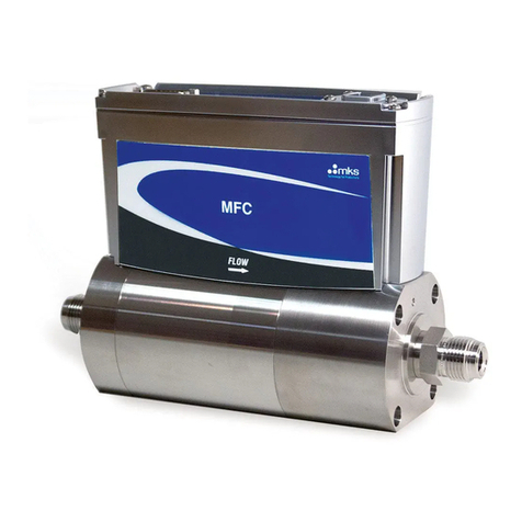
MKS 649B User manual

1023590-001
Rev B, 07/08
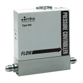
MKS Type 649B
(ROHS Compliant)
Pressure Controller
with an Integral Mass Flow Meter
Instruction Manual

Copyright © 2008 by MKS Instruments, Inc.
All rights reserved. No part of this work may be reproduced or transmitted in any form or by any
means, electronic or mechanical, including photocopying and recording, or by any information
storage or retrieval system, except as may be expressly permitted in writing by MKS Instruments,
Inc.
Baratron®is a registered trademark of MKS Instruments, Inc., Andover, MA
Cajon®and VCR®are registered trademarks of Cajon Company, Macedonia, OH
Viton®is registered trademark of DuPont Dow Elastomers, Inc., Wilmington, DE
Kel-F®is a registered trademark of 3M, Minneapolis, MN
Elgiloy®is a registered trademark of Elgiloy Limited Partnership, Elgin, IL
Protected by U. S. Patent 5461913; foreign patents pending.

Table of Contents
iii
Table of Contents
Safety Information.......................................................................................................................1
Symbols Used in This Instruction Manual......................................................................1
Symbols Found on the Unit............................................................................................2
Sicherheitshinweise......................................................................................................................5
In dieser Betriebsanleitung vorkommende Symbole ......................................................5
Erklärung der am Gerät angebrachten Symbole.............................................................5
Sicherheitsvorschriften und Vorsichtsmaßnahmen.........................................................6
Niemals Teile austauschen oder Änderungen am Gerät vornehmen!..........................................6
Wartung nur durch qualifizierte Fachleute!.................................................................................6
Vorsicht vor stromführenden Leitungen!.....................................................................................6
Vorsicht beim Arbeiten mit gefährlichen Stoffen!.......................................................................6
Spülen des Gerätes mit Gas!........................................................................................................6
Anweisungen zum Spülen des Gerätes........................................................................................6
Gerät nicht zusammen mit explosiven Stoffen, Gasen oder Dämpfen benutzen!........................6
Anweisungen zum Installieren der Armaturen!...........................................................................6
Verbindungen auf Undichtigkeiten prüfen!.................................................................................6
Gerät nur unter zulässigen Anschlussdrücken betreiben!............................................................6
Geeignete Berstscheibe installieren!............................................................................................6
Verunreinigungen im Gerät vermeiden!......................................................................................6
Bei Geräten mit Temperaturkontrolle korrekte Anwärmzeit einhalten!......................................7
Informations de Sécurité..............................................................................................................9
Symboles utilisés dans ce manuel d'utilisation...............................................................9
Symboles figurant sur l'unité ..........................................................................................9
Mesures de sécurité et précautions .................................................................................10
PAS DE REMPLACEMENT DE PIÈCES OU DE MODIFICATION DE L'APPAREIL.........10

Table of Contents
iv
DÉPANNAGE UNIQUEMENT PAR DU PERSONNEL QUALIFIÉ.......................................10
ÉLOIGNEMENT DES CIRCUITS SOUS-TENSION................................................................10
PRÉCAUTION EN CAS D'UTILISATION AVEC DES PRODUITS DANGEREUX.............10
PURGE DE L'APPAREIL...........................................................................................................10
UTILISATION DES PROCÉDURES APPROPRIÉES POUR LA PURGE..............................10
PAS D'EXPLOITATION DANS UN ENVIRONNEMENT EXPLOSIF...................................10
UTILISATION D'ÉQUIPEMENTS ET PROCÉDURES DE SERRAGE APPROPRIÉS .........10
VÉRIFICATION DE L'ÉTANCHÉITÉ DES CONNEXIONS...................................................10
EXPLOITATION AVEC DES PRESSIONS D'ENTRÉE NON DANGEREUSES...................10
INSTALLATION D'UN DISQUE D'ÉCHAPPEMENT ADAPTÉ ............................................10
MAINTIEN DE L'UNITÉ À L'ABRI DES CONTAMINATIONS ............................................10
RESPECT DU TEMPS D'ÉCHAUFFEMENT APPROPRIÉ POUR LES UNITÉS Á
RÉGULATION DE TEMPÉRATURE........................................................................................11
Medidas de Seguridad..................................................................................................................13
Símbolos usados en este manual de instrucciones..........................................................13
Símbolos hallados en la unidad.......................................................................................13
Procedimientos y precauciones de seguridad..................................................................14
NO UTILICE PIEZAS NO ORIGINALES O MODIFIQUE EL INSTRUMENTO...................14
LAS REPARACIONES DEBEN SER EFECTUADAS ÚNICAMENTE POR
TÉCNICOS AUTORIZADOS.....................................................................................................14
MANTÉNGASE ALEJADO DE LOS CIRCUITOS ACTIVOS................................................14
TENGA CUIDADO CUANDO TRABAJE CON MATERIALES TÓXICOS ..........................14
PURGUE EL INSTRUMENTO..................................................................................................14
USE PROCEDIMIENTOS ADECUADOS PARA REALIZAR LA PURGA............................14
NO HAGA FUNCIONAR EL INSTRUMENTO EN AMBIENTES CON RIESGO DE
EXPLOSIÓN ...............................................................................................................................14
USE ACCESORIOS ADECUADOS Y REALICE CORRECTAMENTE LOS
PROCEDIMIENTOS DE AJUSTE.............................................................................................14

Table of Contents
v
COMPRUEBE QUE LOS ACCESORIOS SEAN A PRUEBA DE FUGAS .............................14
HAGA FUNCIONAR EL INSTRUMENTO CON PRESIONES DE ENTRADA
SEGURAS ...................................................................................................................................14
INSTALE UNA CÁPSULA DE SEGURIDAD ADECUADA ..................................................14
MANTENGA LA UNIDAD LIBRE DE CONTAMINANTES..................................................14
CALIENTE ADECUADAMENTE LAS UNIDADES CONTROLADAS POR MEDIO
DE TEMPERATURA..................................................................................................................15
安全に関する情報........................................................................................................................17
本取扱説明書のマーク ....................................................................................................17
本機器のマーク ................................................................................................................17
安全対策について............................................................................................................17
勝手に部品を変えたり、本体を改造しないこと ..............................................................................18
修理は必ず専門の修理サービスを利用すること.............................................................................18
電流が通じている回路から切断すること ........................................................................................18
危険な材料を使用する場合は慎重に機器を使用すること............................................................18
機器を浄化すること.......................................................................................................................18
浄化する場合は適切な手順で行うこと .........................................................................................18
爆発の危険性のある環境で機器を使用しないこと........................................................................18
適切な金具類を使用し、手順に従って金具の締めを行うこと........................................................18
液体の漏れがないよう接続箇所を確認すること.............................................................................18
安全なインレット圧力で使用すること .............................................................................................18
適切なバーストディスクを取り付けること .........................................................................................18
本機器に異物やゴミが混入しないようにすること.............................................................................18
温度調整された機器を十分に温めてから使用すること ..................................................................18
장치 안전 정보............................................................................................................................1
본지침 매뉴얼에 사용되는 기호들.............................................................................1

Table of Contents
vi
장치에 표시된 기호들...................................................................................................1
안전 절차 및예방조치..................................................................................................2
부품을 교체하거나 기계를 개조하지 마십시오......................................................................2
자격이 있는 사람에게만 서비스를 받으십시오......................................................................2
전류가 통하는 회로에서 분리해 보관하십시오......................................................................2
위험한 물질과 함께 작동할 때는 주의를 기울이십시오........................................................2
기계를 청소하십시오.................................................................................................................2
청소 시에는 적절한 절차를 사용하십시오..............................................................................2
폭발성 환경에서 작동하지 마십시오.......................................................................................2
적절한 조립부품과 조임 절차를 사용하십시오......................................................................2
누출방지 조립부품을 점검하십시오........................................................................................2
안전한 흡입 압력에서 작동하십시오.......................................................................................2
적합한 안전 파열판을 설치하십시오.......................................................................................2
장치를 오염이 없는 곳에 보관하십시오..................................................................................3
온도 제어 장치의 경우 알맞은 시동 시간을 두십시오...........................................................3
Chapter One: General Information .............................................................................................5
Introduction.....................................................................................................................5
Design Features of the Integral Mass Flow Meter.............................................5
Cleanliness Features...........................................................................................6
How This Manual is Organized......................................................................................6
Manual Conventions..........................................................................................6
Customer Support...........................................................................................................7
Chapter Two: Installation ...........................................................................................................9
How To Unpack the Type 649 Unit................................................................................9
Opening the Package .........................................................................................9
Unpacking Checklist..........................................................................................10
Interface Cables ..............................................................................................................11

Table of Contents
vii
Generic Shielded Cable Description..................................................................11
Product Location and Requirements...............................................................................12
Dimensions .....................................................................................................................13
Front and Back Views........................................................................................13
Side View...........................................................................................................14
Bottom View......................................................................................................15
Setup ...............................................................................................................................16
Fittings...............................................................................................................16
Mounting Hardware...........................................................................................16
Gas Pressure.......................................................................................................16
Installing the Unit ..............................................................................................17
Electrical Information.....................................................................................................18
I/O Connector ....................................................................................................18
Initial Configuration .......................................................................................................20
Chapter Three: Overview............................................................................................................21
General Information........................................................................................................21
Pressure Control Range .....................................................................................21
Flow Range........................................................................................................22
A Typical Control System .................................................................................22
How The 649 Pressure Controller Works.......................................................................23
Flow Measurement Overview.........................................................................................24
Flow Path...........................................................................................................24
Measurement Technique....................................................................................24
Tuning the 649 Pressure Controller................................................................................25
Proportional Term..............................................................................................25
Integral Term .....................................................................................................26
Tuning the 649 Controller .................................................................................27
Priority of Commands.....................................................................................................29
Trip Points ......................................................................................................................30
Action of the Trip Points ...................................................................................30
Applications with a Large Differential Pressure.............................................................31
Labels..............................................................................................................................31
Chapter Four: Operation.............................................................................................................33

Table of Contents
viii
How To Check the Pressure Transducer Zero ................................................................33
How To Adjust the Pressure Transducer Span ...............................................................34
How To Zero the Integral Mass Flow Meter ..................................................................35
How To Tune the 649 Controller....................................................................................36
How To Adjust the Trip Point Values ............................................................................37
How To Select the Trip Point Action .............................................................................38
How To Use Trip Points as Error Indicators...................................................................40
How To Change the Pressure Output Signal Range.......................................................41
Chapter Five: Maintenance.........................................................................................................43
General Information........................................................................................................43
Zero Adjustment .............................................................................................................43
Appendix A: Product Specifications...........................................................................................45
Performance Specifications.............................................................................................45
Physical Specifications ...................................................................................................46
Environmental Specifications.........................................................................................47
Trip Point Specifications.................................................................................................47
Appendix B: Model Code Explanation.......................................................................................49
Model Code.....................................................................................................................49
Appendix C: Valve Orifice Selection .........................................................................................53
General Information........................................................................................................53
Checking the Valve Orifice Size........................................................................53
How To Verify the Orifice Selection..............................................................................54
Index ............................................................................................................................................57

Table of Contents
ix


List of Figures
xi
List of Figures
Figure 1: Front View of the Type 649 Controller.......................................................................14
Figure 2: Back View of the Type 649 Controller .......................................................................14
Figure 3: Side View (Inlet) of the Type 649 Controller .............................................................15
Figure 4: Bottom View of the Type 649 Controller....................................................................15
Figure 5: Downstream Pressure Control.....................................................................................17
Figure 6: Top View of the Type 649 Controller.........................................................................21
Figure 7: Location of the Mass Flow Meter Adjustments ..........................................................22
Figure 8: Effects of the Proportional Control .............................................................................25
Figure 9: Effects of the Integral Control.....................................................................................26
Figure 10: Controller Response with Initial P Term and I Term Values....................................27
Figure 11: Controller Response with Increased P Term.............................................................28
Figure 12: Controller Response with Increased I Term..............................................................28
Figure 13: Serial Number Label .................................................................................................31
Figure 14: Jumper Positions on the Transducer Board...............................................................39
Figure 15: Flow Range Selection................................................................................................55

List of Figures
xii

List of Tables
xiii
List of Tables
Table 1: Definition of Symbols Found on the Unit ........................................................................2
Tabelle 2: Bedeutung der am Gerät angebrachten Symbole...........................................................5
Tableau 3: Définition des symboles sur l'unité...............................................................................9
Tabla 4: Definición de los símbolos hallados en la unidad...........................................................13
表5: 本機器に使用されているマークについて .................................................................................17
표6: 장치에 표시된 기호들의 정의.............................................................................................1
Table 7: I/O Connector Pinout......................................................................................................18
Table 8: Initial Configuration .......................................................................................................20
Table 9: Highest Pressure for Zero Adjustment of the Pressure Transducer................................ 34
Table 10: Valve Orifice Size......................................................................................................... 53
Table 11: Valve Orifice Index Number ........................................................................................54

List of Tables
xiv

Safety Information
1
Safety Information
Symbols Used in This Instruction Manual
Definitions of WARNING, CAUTION, and NOTE messages used throughout the manual.
Warning
The WARNING sign denotes a hazard. It calls attention to a
procedure, practice, condition, or the like, which, if not
correctly performed or adhered to, could result in injury to
personnel.
Caution
The CAUTION sign denotes a hazard. It calls attention to an
operating procedure, practice, or the like, which, if not correctly
performed or adhered to, could result in damage to or destruction of
all or part of the product.
Note
The NOTE sign denotes important information. It calls attention to a
procedure, practice, condition, or the like, which is essential to highlight.

Safety Information
2
Symbols Found on the Unit
The following table describes symbols that may be found on the unit.
Definition of Symbols Found on the Unit
|
On (Supply)
IEC 417, No.5007
Off (Supply)
IEC 417, No.5008
Earth (ground)
IEC 417, No.5017
Protective earth
(ground)
IEC 417, No.5019
Frame or chassis
IEC 417, No.5020
Equipotentiality
IEC 417, No.5021
Direct current
IEC 417, No.5031
A
lternating current
IEC 417, No.5032
Both direct and
alternating current
IEC 417, No.5033-a Class ll equipment
IEC 417, No.5172-a
Three phase
alternating current
IEC 617-2 No.020206
Caution, refer to
accompanying
documents
ISO 3864, No.B.3.1
Caution, risk of
electric shock
ISO 3864, No.B.3.6 Caution, hot surface
IEC 417, No.5041
Table 1: Definition of Symbols Found on the Unit

Safety Information
3
DO NOT SUBSTITUTE PARTS OR MODIFY INSTRUMENT
Do not install substitute parts or perform any unauthorized modification to the instrument.
Return the instrument to an MKS Calibration and Service Center for service and repair to ensure
that all safety features are maintained.
SERVICE BY QUALIFIED PERSONNEL ONLY
Operating personnel must not remove instrument covers. Component replacement and internal
adjustments must be made by qualified service personnel only.
KEEP AWAY FROM LIVE CIRCUITS
Do not replace components with power cable connected. Under certain conditions, dangerous
voltages may exist even with the power cable removed. To avoid injuries, always disconnect
power and discharge circuits before touching them.
USE CAUTION WHEN OPERATING WITH HAZARDOUS MATERIALS
If hazardous materials are used, users must take responsibility to observe the proper safety
precautions, completely purge the instrument when necessary, and ensure that the material used is
compatible with sealing materials.
PURGE THE INSTRUMENT
After installing the unit, or before its removal from a system, be sure to purge the unit completely
with a clean dry gas to eliminate all traces of the previously used flow material.
USE PROPER PROCEDURES WHEN PURGING
This instrument must be purged under a ventilation hood, and gloves must be worn to protect
personnel.
DO NOT OPERATE IN AN EXPLOSIVE ENVIRONMENT
To avoid explosion, do not operate this product in an explosive environment unless it has been
specifically certified for such operation.

Safety Information
4
USE PROPER FITTINGS AND TIGHTENING PROCEDURES
All instrument fittings must be consistent with instrument specifications, and compatible with the
intended use of the instrument. Assemble and tighten fittings according to manufacturer's
directions.
CHECK FOR LEAK-TIGHT FITTINGS
Before proceeding to instrument setup, carefully check all plumbing connections to the
instrument to ensure leak-tight installation.
OPERATE AT SAFE INLET PRESSURES
This unit should never be operated at pressures higher than the rated maximum pressure (refer to
the product specifications for the maximum allowable pressure).
INSTALL A SUITABLE BURST DISC
When operating from a pressurized gas source, a suitable burst disc should be installed in the
vacuum system to prevent system explosion should the system pressure rise.
KEEP THE UNIT FREE OF CONTAMINANTS
Do not allow contaminants of any kind to enter the unit before or during use. Contamination
such as dust, dirt, lint, glass chips, and metal chips may permanently damage the unit.

Sicherheitshinweise
5
Sicherheitshinweise
In dieser Betriebsanleitung vorkommende Symbole
Bedeutung der mit WARNUNG!, VORSICHT! und HINWEIS gekennzeichneten Absätze in dieser
Betriebsanleitung.
Warnung! Das Symbol WARNUNG! weist auf eine Gefahr für das Bedienpersonal hin. Es
macht auf einen Arbeitsablauf, eine Arbeitsweise, einen Zustand oder eine
sonstige Gegebenheit aufmerksam, deren unsachgemäße Ausführung bzw.
ungenügende Berücksichtigung zu Verletzungen führen kann.
Vorsicht! Das Symbol VORSICHT! weist auf eine Gefahr für das Gerät hin. Es macht auf
einen Bedienungsablauf, eine Arbeitsweise oder eine sonstige Gegebenheit
aufmerksam, deren unsachgemäße Ausführung bzw. ungenügende
Berücksichtigung zu einer Beschädigung oder Zerstörung des Gerätes oder von
Teilen des Gerätes führen kann.
Hinweis Das Symbol HINWEIS macht auf wichtige Informationen bezüglich eines
Arbeitsablaufs, einer Arbeitsweise, eines Zustands oder einer sonstige Gegebenheit
aufmerksam.
Erklärung der am Gerät angebrachten Symbole
Nachstehender Tabelle sind die Bedeutungen der Symbole zu entnehmen, die am Gerät angebracht sein können.
Tabelle 2: Bedeutung der am Gerät angebrachten Symbole
|
Ein (Energie)
IEC 417, No.5007 Aus (Energie)
IEC 417, No.5008 Erdanschluss
IEC 417, No.5017 Schutzleiteranschluss
IEC 417, No.5019
Masseanschluss
IEC 417, No.5020 Aquipotentialanschluss
IEC 417, No.5021 Gleichstrom
IEC 417, No.5031 Wechselstrom
IEC 417, No.5032
Gleich- oder Wechselstrom
IEC 417, No.5033-a Durchgängige doppelte oder
verstärkte Isolierung
IEC 417, No.5172-a
Dreileiter-Wechselstrom (Drehstrom)
IEC 617-2, No.020206
Warnung vor einer Gefahrenstelle
(Achtung, Dokumentation beachten)
ISO 3864, No.B.3.1
Warnung vor gefährlicher
elektrischer Spannung
ISO 3864, No.B.3.6
Höhere Temperatur an leicht
zugänglichen Teilen
IEC 417, No.5041

Sicherheitshinweise
6
Sicherheitsvorschriften und Vorsichtsmaßnahmen
Folgende allgemeine Sicherheitsvorschriften sind während allen Betriebsphasen dieses Gerätes zu
befolgen. Eine Missachtung der Sicherheitsvorschriften und sonstiger Warnhinweise in dieser
Betriebsanleitung verletzt die für dieses Gerät und seine Bedienung geltenden Sicherheitsstandards,
und kann die Schutzvorrichtungen an diesem Gerät wirkungslos machen. MKS Instruments, Inc.
haftet nicht für Missachtung dieser Sicherheitsvorschriften seitens des Kunden.
Niemals Teile austauschen oder Änderungen am Gerät vornehmen!
Ersetzen Sie keine Teile mit baugleichen oder ähnlichen Teilen, und nehmen Sie keine eigenmächtigen Änderungen am
Gerät vor. Schicken Sie das Gerät zwecks Wartung und Reparatur an den MKS-Kalibrierungs- und -Kundendienst ein.
Nur so wird sichergestellt, dass alle Schutzvorrichtungen voll funktionsfähig bleiben.
Wartung nur durch qualifizierte Fachleute!
Das Auswechseln von Komponenten und das Vornehmen von internen Einstellungen darf nur von qualifizierten
Fachleuten durchgeführt werden, niemals vom Bedienpersonal.
Vorsicht vor stromführenden Leitungen!
Ersetzen Sie keine Komponente von Geräten, die an Netzstrom angeschlossen sind. Unter Umständen kann gefährliche
Spannung auch dann bestehen, wenn das Netzanschlusskabel von der Strmversorgung entfernt wurde. Um Verletzungen
vorzubeugen sollten zuerst alle Geräte von der Stromversorgung getrennt und alle Stromkreusläufe entladen werden.
Vorsicht beim Arbeiten mit gefährlichen Stoffen!
Wenn gefährliche Stoffe verwendet werden, muss der Bediener die entsprechenden Sicherheitsvorschriften genauestens
einhalten, das Gerät, falls erforderlich, vollständig spülen, sowie sicherstellen, dass der Gefahrstoff die am Gerät
verwendeten Materialien, insbesondere Dichtungen, nicht angreift.
Spülen des Gerätes mit Gas!
Nach dem Installieren oder vor dem Ausbau aus einem System muss das Gerät unter Einsatz eines reinen Trockengases
vollständig gespült werden, um alle Rückstände des Vorgängermediums zu entfernen.
Anweisungen zum Spülen des Gerätes
Das Gerät darf nur unter einer Ablufthaube gespült werden. Schutzhandschuhe sind zu tragen.
Gerät nicht zusammen mit explosiven Stoffen, Gasen oder Dämpfen benutzen!
Um der Gefahr einer Explosion vorzubeugen, darf dieses Gerät niemals zusammen mit (oder in der Nähe von)
explosiven Stoffen aller Art eingesetzt werden, sofern es nicht ausdrücklich für diesen Zweck zugelassen ist.
Anweisungen zum Installieren der Armaturen!
Alle Anschlussstücke und Armaturenteile müssen mit der Gerätespezifikation übereinstimmen, und mit dem geplanten
Einsatz des Gerätes kompatibel sein. Der Einbau, insbesondere das Anziehen und Abdichten, muss gemäß den
Anweisungen des Herstellers vorgenommen werden.
Verbindungen auf Undichtigkeiten prüfen!
Überprüfen Sie sorgfältig alle Verbindungen der Vakuumkomponenten auf undichte Stellen.
Gerät nur unter zulässigen Anschlussdrücken betreiben!
Betreiben Sie das Gerät niemals unter Drücken, die den maximal zulässigen Druck (siehe Produktspezifikationen)
übersteigen.
Geeignete Berstscheibe installieren!
Wenn mit einer unter Druck stehenden Gasquelle gearbeitet wird, sollte eine geeignete Berstscheibe in das
Vakuumsystem installiert werden, um eine Explosionsgefahr aufgrund von steigendem Systemdruck zu vermeiden.
Verunreinigungen im Gerät vermeiden!
Other manuals for 649B
1
Table of contents
Other MKS Controllers manuals
Popular Controllers manuals by other brands

Afriso EURO-INDEX
Afriso EURO-INDEX RG 210 instruction manual

Eaton
Eaton MFD-Titan MFD-80 Series Instruction leaflet

Renesas
Renesas Applilet user manual

LEGRAND
LEGRAND 0 784 48 quick start guide

Southwest Windpower
Southwest Windpower AIR-X datasheet

Compit
Compit SOLARCOMP 951 Installation and operating instructions