MKS 649A User manual

121004-P1
Rev A, 11/97
Instruction Manual
MKS Type 649A
Pressure Controller
with an Integral Mass Flow Meter
Six Shattuck Road
Andover, MA 01810-2449
(800) 227-8766 or (978) 975-2350
Fax: (978) 975-0093
E-mail: mks@mksinst.com
Web site: http://www.mksinst.com

WARRANTY
Type 649A Equipment
MKS Instruments, Inc. (MKS) warrants that for two years from the date of shipment
the equipment described above (the “equipment”) manufactured by MKS shall be
free from defects in materials and workmanship and will correctly perform all date-
related operations, including without limitation accepting data entry, sequencing,
sorting, comparing, and reporting, regardless of the date the operation is performed
or the date involved in the operation, provided that, if the equipment exchanges
data or is otherwise used with equipment, software, or other products of others,
such products of others themselves correctly perform all date-related operations
and store and transmit dates and date-related data in a format compatible with
MKS equipment. THIS WARRANTY IS MKS’ SOLE WARRANTY CONCERNING
DATE-RELATED OPERATIONS.
For the period commencing with the date of shipment of this equipment and ending
two years later, MKS will, at its option, either repair or replace any part which is
defective in materials or workmanship or with respect to the date-related operations
warranty without charge to the purchaser. The foregoing shall constitute the
exclusive and sole remedy of the purchaser for any breach by MKS of this
warranty.
The purchaser, before returning any equipment covered by this warranty, which is
asserted to be defective by the purchaser, shall make specific written arrange-
ments with respect to the responsibility for shipping the equipment and handling
any other incidental charges with the MKS sales representative or distributor from
which the equipment was purchased or, in the case of a direct purchase from MKS,
with the MKS home office in Andover, Massachusetts, USA.
This warranty does not apply to any equipment which has not been installed and
used in accordance with the specifications recommended by MKS for the proper
and normal use of the equipment. MKS shall not be liable under any circumstances
for indirect, special, consequential, or incidental damages in connection with, or
arising out of, the sale, performance, or use of the equipment covered by this
warranty.
MKS recommends that all MKS pressure and flow products be calibrated
periodically (typically every 6 to 12 months) to ensure accurate readings. When a
product is returned to MKS for this periodic re-calibration it is considered normal
preventative maintenance not covered by any warranty.
THIS WARRANTY IS IN LIEU OF ALL OTHER RELEVANT WARRANTIES,
EXPRESSED OR IMPLIED, INCLUDING THE IMPLIED WARRANTY OF
MERCHANTABILITY AND THE IMPLIED WARRANTY OF FITNESS FOR A
PARTICULAR PURPOSE, AND ANY WARRANTY AGAINST INFRINGEMENT OF
ANY PATENT.
11-98 121004-P1

121004-P1
Rev A, 11/97
MKS Type 649A
Pressure Controller
with an Integral Mass Flow Meter

Copyright © 1997 by MKS Instruments, Inc.
All rights reserved. No part of this work may be reproduced or transmitted in any form or by
any means, electronic or mechanical, including photocopying and recording, or by any
information storage or retrieval system, except as may be expressly permitted in writing by MKS
Instruments, Inc.
Baratronis a registered trademark of MKS Instruments, Inc., Andover, MA
Cajonand VCRare registered trademarks of Cajon Company, Macedonia, OH
Vitonis registered trademark of DuPont Dow Elastomers, Inc., Wilmington, DE
Kel-Fis a registered trademark of 3M, Minneapolis, MN
Elgiloyis a registered trademark of Elgiloy Limited Partnership, Elgin, IL
Protected by U. S. Patent 5461913; foreign patents pending.

Table of Contents
iii
Table of Contents
Safety Information.................................................................................................................. 1
Symbols Used in This Instruction Manual.................................................................. 1
Symbols Found on the Unit ....................................................................................... 2
Chapter One: General Information......................................................................................... 5
Introduction............................................................................................................... 5
Design Features of the Integral Mass Flow Meter.......................................... 5
Cleanliness Features...................................................................................... 6
How This Manual is Organized.................................................................................. 6
Manual Conventions ..................................................................................... 6
Customer Support...................................................................................................... 7
Chapter Two: Installation......................................................................................................9
How To Unpack the Type 649 Unit ........................................................................... 9
Opening the Package..................................................................................... 9
Unpacking Checklist ..................................................................................... 10
Interface Cables ......................................................................................................... 11
Generic Shielded Cable Description .............................................................. 11
Product Location and Requirements........................................................................... 12
Dimensions................................................................................................................ 13
Front and Back Views................................................................................... 13
Side View ..................................................................................................... 14
Bottom View................................................................................................. 15
Setup ......................................................................................................................... 16
Fittings.......................................................................................................... 16
Mounting Hardware ...................................................................................... 16
Gas Pressure.................................................................................................. 16
Installing the Unit.......................................................................................... 17
Electrical Information................................................................................................ 18
I/O Connector................................................................................................ 18
Initial Configuration .................................................................................................. 20

Table of Contents
iv
Chapter Three: Overview.......................................................................................................21
General Information ...................................................................................................21
Pressure Control Range..................................................................................21
Flow Range ...................................................................................................22
A Typical Control System..............................................................................22
How The 649 Pressure Controller Works....................................................................23
Flow Measurement Overview.....................................................................................24
Flow Path ......................................................................................................24
Measurement Technique................................................................................24
Tuning the 649 Pressure Controller ............................................................................25
Proportional Term..........................................................................................25
Integral Term.................................................................................................26
Tuning the 649 Controller..............................................................................27
Priority of Commands................................................................................................29
Trip Points .................................................................................................................30
Action of the Trip Points................................................................................30
Applications with a Large Differential Pressure..........................................................31
Labels ........................................................................................................................31
The Gas Correction Factor (GCF) for Flow Metering .................................................32
Chapter Four: Operation ........................................................................................................33
How To Check the Pressure Transducer Zero .............................................................33
How To Adjust the Pressure Transducer Span............................................................34
How To Zero the Integral Mass Flow Meter...............................................................35
How To Tune the 649 Controller................................................................................36
How To Adjust the Trip Point Values.........................................................................37
How To Select the Trip Point Action..........................................................................38
How To Use Trip Points as Error Indicators ...............................................................40
How To Change the Pressure Output Signal Range ....................................................41
Chapter Five: Maintenance ....................................................................................................43
General Information ...................................................................................................43
Zero Adjustment ........................................................................................................43
Appendix A: Product Specifications.......................................................................................45

Table of Contents
v
Performance Specifications........................................................................................ 45
Physical Specifications .............................................................................................. 46
Environmental Specifications..................................................................................... 47
Trip Point Specifications............................................................................................ 47
Appendix B: Model Code Explanation.................................................................................. 49
Model Code............................................................................................................... 49
Appendix C: Valve Orifice Selection..................................................................................... 53
General Information................................................................................................... 53
Checking the Valve Orifice Size.................................................................... 53
How To Verify the Orifice Selection.......................................................................... 54
Using Different Gases ................................................................................... 56
Appendix D: Gas Correction Factors..................................................................................... 59
Index...................................................................................................................................... 63

Table of Contents
vi

List of Fi
g
ures
vii
List of Figures
Figure 1: Front View of the Type 649 Controller................................................................... 13
Figure 2: Back View of the Type 649 Controller ................................................................... 14
Figure 3: Side View (Inlet) of the Type 649 Controller.......................................................... 14
Figure 4: Bottom View of the Type 649 Controller................................................................ 15
Figure 5: Downstream Pressure Control ................................................................................ 17
Figure 6: Top View of the Type 649 Controller..................................................................... 21
Figure 7: Location of the Mass Flow Meter Adjustments....................................................... 22
Figure 8: Effects of the Proportional Control......................................................................... 25
Figure 9: Effects of the Integral Control ................................................................................ 26
Figure 10: Controller Response with Initial P Term and I Term Values ................................. 27
Figure 11: Controller Response with Increased P Term ......................................................... 28
Figure 12: Controller Response with Increased I Term .......................................................... 28
Figure 13: Serial Number Label............................................................................................. 31
Figure 14: Jumper Positions on the Transducer Board ........................................................... 39
Figure 15: Flow Range Selection........................................................................................... 55

List of Figures
viii

List of Tables
ix
List of Tables
Table 1: Definition of Symbols Found on the Unit .....................................................................2
Table 2: I/O Connector Pinout..................................................................................................18
Table 3: Initial Configuration...................................................................................................20
Table 4: Highest Pressure for Zero Adjustment of the Pressure Transducer...............................34
Table 5: Valve Orifice Size ......................................................................................................53
Table 6: Valve Orifice Index Number.......................................................................................54

List of Tables
x

Safety Information
1
Safety Information
Symbols Used in This Instruction Manual
Definitions of WARNING, CAUTION, and NOTE messages used throughout the manual.
Warning The WARNING sign denotes a hazard. It calls attention to a
procedure, practice, condition, or the like, which, if not
correctly performed or adhered to, could result in injury to
personnel.
Caution The CAUTION sign denotes a hazard. It calls attention to an
operating procedure, practice, or the like, which, if not correctly
performed or adhered to, could result in damage to or destruction of
all or part of the product.
Note The NOTE sign denotes important information. It calls attention to a
procedure, practice, condition, or the like, which is essential to highlight.

Safet
y
Information
2
Symbols Found on the Unit
The following table describes symbols that may be found on the unit.
Definition of Symbols Found on the Unit
|
On (Supply)
IEC 417, No.5007 Off (Supply)
IEC 417, No.5008 Earth (
g
round)
IEC 417, No.5017
Protective earth
(
g
round)
IEC 417, No.5019
Frame or chassis
IEC 417, No.5020 Equipotentiality
IEC 417, No.5021 Direct current
IEC 417, No.5031 Alternatin
g
current
IEC 417, No.5032
Both direct and
alternatin
g
current
IEC 417, No.5033-a Class ll equipment
IEC 417, No.5172-a
Three phase
alternatin
g
current
IEC 617-2 No.020206
Caution, refer to
accompanyin
g
documents
ISO 3864, No.B.3.1
Caution, risk of
electric shock
ISO 3864, No.B.3.6 Caution, hot surface
IEC 417, No.5041
Table 1: Definition of Symbols Found on the Unit

Safety Information
3
DO NOT SUBSTITUTE PARTS OR MODIFY INSTRUMENT
Do not install substitute parts or perform any unauthorized modification to the instrument.
Return the instrument to an MKS Calibration and Service Center for service and repair to ensure
that all safety features are maintained.
SERVICE BY QUALIFIED PERSONNEL ONLY
Operating personnel must not remove instrument covers. Component replacement and internal
adjustments must be made by qualified service personnel only.
KEEP AWAY FROM LIVE CIRCUITS
Do not replace components with power cable connected. Under certain conditions, dangerous
voltages may exist even with the power cable removed. To avoid injuries, always disconnect
power and discharge circuits before touching them.
USE CAUTION WHEN OPERATING WITH HAZARDOUS MATERIALS
If hazardous materials are used, users must take responsibility to observe the proper safety
precautions, completely purge the instrument when necessary, and ensure that the material used
is compatible with sealing materials.
PURGE THE INSTRUMENT
After installing the unit, or before its removal from a system, be sure to purge the unit completely
with a clean dry gas to eliminate all traces of the previously used flow material.
USE PROPER PROCEDURES WHEN PURGING
This instrument must be purged under a ventilation hood, and gloves must be worn to protect
personnel.
DO NOT OPERATE IN AN EXPLOSIVE ENVIRONMENT
To avoid explosion, do not operate this product in an explosive environment unless it has been
specifically certified for such operation.

Safet
y
Information
4
USE PROPER FITTINGS AND TIGHTENING PROCEDURES
All instrument fittings must be consistent with instrument specifications, and compatible with the
intended use of the instrument. Assemble and tighten fittings according to manufacturer's
directions.
CHECK FOR LEAK-TIGHT FITTINGS
Before proceeding to instrument setup, carefully check all plumbing connections to the
instrument to ensure leak-tight installation.
OPERATE AT SAFE INLET PRESSURES
This unit should never be operated at pressures higher than the rated maximum pressure (refer to
the product specifications for the maximum allowable pressure).
INSTALL A SUITABLE BURST DISC
When operating from a pressurized gas source, a suitable burst disc should be installed in the
vacuum system to prevent system explosion should the system pressure rise.
KEEP THE UNIT FREE OF CONTAMINANTS
Do not allow contaminants of any kind to enter the unit before or during use. Contamination
such as dust, dirt, lint, glass chips, and metal chips may permanently damage the unit.

Chapter One: General Information Introduction
5
Chapter One: General Information
Introduction
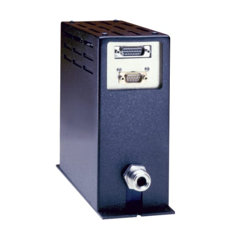
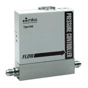
The MKS Type 649A Pressure Controller with an Integral Mass Flow Meter combines pressure
control and flow metering capabilities into one compact unit. The 649 pressure controller
includes a Baratroncapacitance manometer, proportioning control valve, closed-loop
electronics, and patented thermal mass flow sensor. The closed-loop control circuitry enables the
unit to function as a proportional-integral (PI) controller. The combination of a pressure
controller and mass flow meter in one unit makes the 649 pressure controller the ideal solution
for backside wafer cooling applications. In addition, the unit’s compact size and small footprint
reduce space requirements compared to multi-component systems.
The 649 pressure controller is available with full scale pressure ranges from 10 to 1000 Torr and
full scale flow rates from 10 to 5000 sccm (nitrogen equivalent). The 649 unit is metal sealed;
the valve plug material can be metal, Viton, Kel-F, or Kalrez. The unit can have either
Cajon4-VCRmale (or equivalent) or 8-VCR male (or equivalent) male fittings.
One Type “D” connector, located on the top of the unit, accepts the input power and has both the
pressure (input and output) and flow (output) signals. You can connect the 649 controller to an
MKS Type 247 or 246 Mass Flow Controller Power Supply/Readout or a Type 647 Mass Flow
and Pressure Programmer/Display unit.
The 649 pressure controller provides two user-settable alarm trip points. The pressure trip points
can be set from 1 to 100% of full scale. Each trip point controls an open collector transistor. An
LED light located on the top of the unit, indicates the trip point status.
Caution The control valve within the 649 unit is not a positive shutoff valve.
You may need to install a separate positive shutoff valve in your
system.
Design Features of the Integral Mass Flow Meter
The design of the integral mass flow meter incorporates an advanced flow sensor (U.S. Patent1;
Foreign Patents Pending) and an optimized bypass. The latest generation two-element sensing
circuit provides accurate, repeatable performance even in low flow ranges (< 10 sccm). Low
temperature effect from ambient temperature change and a low attitude sensitivity effect are also
ensured. The newly optimized sensor/bypass arrangement minimizes the flow splitting error for
gases with different densities, which dramatically improves measurement accuracy when gases
other than the calibration gas are used.
1U.S. Patent 5461913; foreign patents pending.

How This Manual is Organized Cha
p
ter One: General Information
6
Cleanliness Features
The design of the pressure controller ensures extremely low external leakage and minimizes a
key source of particle generation, outgassing, and permeation. The design also incorporates
minimal wetted surface area. To further ensure its cleanliness, the 649 controller undergoes
precision machining as well as a proprietary cleaning process. The instrument is assembled and
double-bagged in a Class 100 clean room.
How This Manual is Organized
This manual is designed to provide instructions on how to set up, install, and operate a Type 649
unit.
Before installing your Type 649 unit in a system and/or operating it, carefully read and
familiarize yourself with all precautionary notes in the Safety Messages and Procedures
section at the front of this manual. In addition, observe and obey all WARNING and
CAUTION notes provided throughout the manual.
Chapter One, General Information, (this chapter) introduces the product and describes the
organization of the manual.
Chapter Two, Installation, explains the environmental requirements and describes how to mount
the instrument in your system.
Chapter Three, Overview, gives a brief description of the instrument and its functionality.
Chapter Four, Operation, describes how to use the instrument and explains all the functions and
features.
Chapter Five, Maintenance, lists any maintenance required to keep the instrument in good
working condition.
Chapter Six, Troubleshooting, provides a reference should the instrument malfunction.
Appendix A: Product Specifications, lists the specifications of the instrument.
Appendix B: Model Code Explanation, describes the model code.
Appendix C: Valve Orifice Selection, presents the information used to select the appropriate flow
range for nitrogen and other gases.
Appendix D: Gas Correction Factors, lists the gas correction factors of commonly used gases.
Manual Conventions
The following conventions apply throughout this manual:
XXXXXX For inputs: Indicates that the line must be pulled low to activate the function.
XXXXXX For outputs: Indicates that the output is active low.

Chapter One: General Information Customer Su
pp
ort
7
Customer Support
Standard maintenance and repair services are available through all of our regional MKS
Calibration and Service Centers, listed on the back cover. In addition, MKS accepts the
instruments of other manufacturers for recalibration using the Primary and Transfer Standard
calibration equipment located at all of our regional service centers. Should any difficulties arise
in the use of your Type 649 instrument, or to obtain information about companion products MKS
offers, contact any authorized MKS Calibration and Service Center. If it is necessary to return
the instrument to MKS, please obtain an ERA Number (Equipment Return Authorization
Number) from the MKS Calibration and Service Center before shipping. The ERA Number
expedites handling and ensures proper servicing of your instrument.
Please refer to the inside of the back cover of this manual for a list of MKS Calibration and
Service Centers.
Warning All returns to MKS Instruments must be free of harmful,
corrosive, radioactive, or toxic materials.

Customer Support Cha
p
ter One: General Information
8
This page intentionally left blank.
Table of contents
Other MKS Controllers manuals