MKS 653B User manual

117082-P1
Rev D, 1/98
Instruction Manual
MKS Type 653B
Exhaust Throttle Valve
Six Shattuck Road
Andover, MA 01810-2449
(800) 227-8766 or (978) 975-2350
Fax: (978) 975-0093
E-mail: mks@mksinst.com
Web site: http://www.mksinst.com

WARRANTY
Type 653B Equipment
MKS Instruments, Inc. (MKS) warrants that for two years from the date of shipment
the equipment described above (the “equipment”) manufactured by MKS shall be
free from defects in materials and workmanship and will correctly perform all date-
related operations, including without limitation accepting data entry, sequencing,
sorting, comparing, and reporting, regardless of the date the operation is performed
or the date involved in the operation, provided that, if the equipment exchanges
data or is otherwise used with equipment, software, or other products of others,
such products of others themselves correctly perform all date-related operations
and store and transmit dates and date-related data in a format compatible with
MKS equipment. THIS WARRANTY IS MKS’ SOLE WARRANTY CONCERNING
DATE-RELATED OPERATIONS.
For the period commencing with the date of shipment of this equipment and ending
two years later, MKS will, at its option, either repair or replace any part which is
defective in materials or workmanship or with respect to the date-related operations
warranty without charge to the purchaser. The foregoing shall constitute the
exclusive and sole remedy of the purchaser for any breach by MKS of this
warranty.
The purchaser, before returning any equipment covered by this warranty, which is
asserted to be defective by the purchaser, shall make specific written arrange-
ments with respect to the responsibility for shipping the equipment and handling
any other incidental charges with the MKS sales representative or distributor from
which the equipment was purchased or, in the case of a direct purchase from MKS,
with the MKS home office in Andover, Massachusetts, USA.
This warranty does not apply to any equipment which has not been installed and
used in accordance with the specifications recommended by MKS for the proper
and normal use of the equipment. MKS shall not be liable under any circumstances
for indirect, special, consequential, or incidental damages in connection with, or
arising out of, the sale, performance, or use of the equipment covered by this
warranty.
MKS recommends that all MKS pressure and flow products be calibrated
periodically (typically every 6 to 12 months) to ensure accurate readings. When a
product is returned to MKS for this periodic re-calibration it is considered normal
preventative maintenance not covered by any warranty.
THIS WARRANTY IS IN LIEU OF ALL OTHER RELEVANT WARRANTIES,
EXPRESSED OR IMPLIED, INCLUDING THE IMPLIED WARRANTY OF
MERCHANTABILITY AND THE IMPLIED WARRANTY OF FITNESS FOR A
PARTICULAR PURPOSE, AND ANY WARRANTY AGAINST INFRINGEMENT OF
ANY PATENT.
11-98 117082-P1
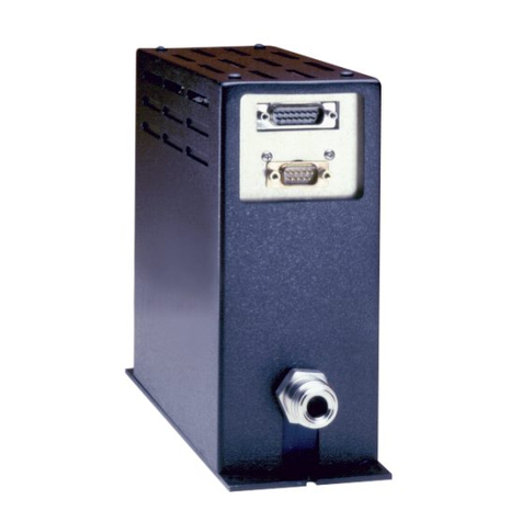
117082-P1

Rev D, 1/98
MKS Type 653B
Exhaust Throttle Valve

Copyright © 1998 by MKS Instruments, Inc.
All rights reserved. No part of this work may be reproduced or transmitted in any form or by
any means, electronic or mechanical, including photocopying and recording, or by any
information storage or retrieval system, except as may be expressly permitted in writing by MKS
Instruments, Inc.
Printed in the United States of America
Baratron®is a registered trademark of MKS Instruments, Inc., Andover, MA
Chemraz®is a registered trademark of Greene, Tweed & Co., Inc., Kulpsville, PA
Viton®and Kalrez®are registered trademarks of DuPont Dow Elastomers, Inc., Wilmington, DE
Parker®is a registered trademark of Parker Seals, Lexington, KY
Please Note:
MKS Instruments provides these documents as the latest version for the revision indicated.
The material is subject to change without notice, and should be verified if used in a critical
application.

Table of Contents
iii
Table of Contents
Valve Safety Information ....................................................................................................... 1
Symbols Used in This Instruction Manual.................................................................. 1
Symbols Found on the Unit ....................................................................................... 2
Safety Procedures and Precautions............................................................................. 3
Chapter One: General Information......................................................................................... 5
Introduction............................................................................................................... 5
How This Manual is Organized.................................................................................. 6
Customer Support...................................................................................................... 6
Chapter Two: Installation......................................................................................................7
How To Unpack the Type 653 Unit ........................................................................... 7
Unpacking Checklist ..................................................................................... 7
Environmental Requirements..................................................................................... 8
Setup ......................................................................................................................... 8
Choosing A Pressure Controller .................................................................... 9
Flange Types ............................................................................................................. 9
ASA Series Flanges....................................................................................... 10
CF Series Flanges.......................................................................................... 11
ISO-NW Series Flanges................................................................................. 12
JIS Series Flanges ......................................................................................... 13
KF Series Flanges ......................................................................................... 14
Interface Cables ......................................................................................................... 15
Generic Shielded Cable Description .............................................................. 16
Interface Connector.................................................................................................... 17
Chapter Three: Operation ...................................................................................................... 19
Theory of Operation................................................................................................... 19
General Operation Information................................................................................... 20
Chapter Four: Maintenance ................................................................................................... 21
General Information................................................................................................... 21

Table of Contents
iv
Safety Precautions .........................................................................................21
Cleaning the Valve.....................................................................................................22
Appendix A: Product Specifications.......................................................................................23
General Specifications................................................................................................23
Appendix B: ASA Series Flange Specifications.....................................................................25
Appendix C: ISO-NW Series Flange Specifications...............................................................27
Appendix D: CF Series Flange Specifications........................................................................29
Appendix E: JIS Series Flange Specifications........................................................................31
Index ......................................................................................................................................33

List of Fi
g
ures and Tables
v
List of Figures and Tables
Figures
Figure 1: Outline Dimensions of the Motor Driver Assembly................................................ 9
Figure 2: Outline Dimensions of an ASA Series Flange......................................................... 10
Figure 3: Outline Dimensions of a CF Series Flange ............................................................. 11
Figure 4: Outline Dimensions of an ISO-NW Series Flange .................................................. 12
Figure 5: Outline Dimensions of a JIS Series Flange............................................................. 13
Figure 6: Outline Dimensions of a KF Series Flange............................................................. 14
Tables
Table 1: Definition of Symbols Found on the Unit .....................................................................2
Table 2: Size Options for ASA Series Flanges..........................................................................10
Table 3: Size Options for CF Series Flanges.............................................................................11
Table 4: Size Options for ISO-NW Series Flanges....................................................................12
Table 5: Size Options for JIS Series Flanges.............................................................................13
Table 6: Size Options for KF Series Flanges.............................................................................14
Table 7: Interface Cables..........................................................................................................15
Table 8: Interface Connector Pinout .........................................................................................17

List of Figures and Tables
vi

Valve Safety Information S
y
mbols Used in This Instruction Manual
1
Valve Safety Information
Symbols Used in This Instruction Manual
Definitions of WARNING, CAUTION, and NOTE messages used throughout the manual.
Warning The WARNING sign denotes a hazard to personnel. It calls
attention to a procedure, practice, condition, or the like,
which, if not correctly performed or adhered to, could result
in injury to personnel.
Caution The CAUTION sign denotes a hazard to equipment. It calls
attention to an operating procedure, practice, or the like, which, if
not correctly performed or adhered to, could result in damage to or
destruction of all or part of the product.
Note The NOTE sign denotes important information. It calls attention to a
procedure, practice, condition, or the like, which is essential to highlight.

Symbols Found on the Unit Valve Safet
y
Information
2
Symbols Found on the Unit
The following table describes symbols that may be found on the unit.
Definition of Symbols Found on the Unit
|
On (Supply)
IEC 417, No.5007 Off (Supply)
IEC 417, No.5008 Earth (
g
round)
IEC 417, No.5017
Protective earth
(
g
round)
IEC 417, No.5019
Frame or chassis
IEC 417, No.5020 Equipotentiality
IEC 417, No.5021 Direct current
IEC 417, No.5031 Alternatin
g
current
IEC 417, No.5032
Both direct and
alternatin
g
current
IEC 417, No.5033-a Class ll equipment
IEC 417, No.5172-a
Three phase
alternatin
g
current
IEC 617-2 No.020206
Caution, refer to
accompanyin
g
documents
ISO 3864, No.B.3.1
Caution, risk of
electric shock
ISO 3864, No.B.3.6 Caution, hot surface
IEC 417, No.5041
Table 1: Definition of Symbols Found on the Unit

Valve Safety Information Safet
y
Procedures and Precautions
3
Safety Procedures and Precautions
Observe the following general safety precautions during all phases of valve operation. Failure
to comply with these precautions or with specific warnings elsewhere in this manual violates
safety standards of intended use of the valve and may impair the protection provided by the
equipment. MKS Instruments, Inc. assumes no liability for the customer’s failure to comply
with these requirements.
Warning Moving parts in the valve create a risk of personal injury until
the valve is securely incorporated into a system. To avoid
injury, keep all bodily parts away from any valve opening.
1. Do not insert objects into openings where contact with
moving parts is possible.
2. Isolate the valve from any electrical or pneumatic power
supply before handling the valve.
DO NOT SUBSTITUTE PARTS OR MODIFY VALVE
Do not install substitute parts or perform any unauthorized modification to the valve. Return the
valve to an MKS Calibration and Service Center for service and repair to ensure that all safety
features are maintained.
SERVICE BY QUALIFIED PERSONNEL ONLY
Operating personnel must not attempt component replacement and internal adjustments. Any
service must be performed by qualified service personnel only.
USE CAUTION WHEN OPERATING WITH HAZARDOUS MATERIALS
If hazardous materials are used, observe the proper safety precautions, completely purge the
valve when necessary, and ensure that the material used is compatible with the wetted materials
in this product, including any sealing materials.
PURGE THE VALVE
After installing the unit, or before removing it from a system, purge the unit completely with a
clean, dry gas to eliminate all traces of the previously used flow material.
USE PROPER PROCEDURES WHEN PURGING
This valve must be purged under a ventilation hood, and gloves must be worn for protection.

Safety Procedures and Precautions Valve Safet
y
Information
4
DO NOT OPERATE IN AN EXPLOSIVE ENVIRONMENT
To avoid explosion, do not operate this product in an explosive environment unless it has been
specifically certified for such operation.
USE PROPER FITTINGS AND TIGHTENING PROCEDURES
All valve fittings must be consistent with valve specifications, and compatible with the intended
use of the valve. Assemble and tighten fittings according to manufacturer's directions.
CHECK FOR LEAK-TIGHT FITTINGS
Carefully check all vacuum component connections to ensure leak-tight installation.
OPERATE AT SAFE INLET PRESSURES
Never operate the valve at pressures higher than the rated maximum pressure (refer to the product
specifications for the maximum allowable pressure).
INSTALL A SUITABLE BURST DISC
When operating from a pressurized gas source, install a suitable burst disc in the vacuum system
to prevent system explosion should the system pressure rise.
KEEP THE UNIT FREE OF CONTAMINANTS
Do not allow contaminants to enter the unit before or during use. Contamination such as dust,
dirt, lint, glass chips, and metal chips may permanently damage the unit or contaminate the
process.
KEEP AWAY FROM VALVE OPENING
Keep fingers, other body parts, and other materials away from the valve opening when the valve
is in operation.

Chapter One: General Information Introduction
5
Chapter One: General Information
Introduction
The Type 653B Exhaust Throttle Valve is designed for a wide range of pressure control
conductance and has the high torque rating necessary for sealing-type and large-size valves. The
653’s motor and gear/driver assembly combined with the Type 651, Type 1651 or Type 652B
Self-Tuning Controller, provides fast and precise pressure control over the entire operating range
of the valve. High accuracy control is attained by micro-stepping the flapper to give more
precise control of the pressure at the desired pressure set point without drift around the set point.
The Type 653 valve has a torque reserve exceeding that which is required to operate a
4-inch sealing valve or a 12-inch non-sealing valve and is constructed of corrosion-resistant 316L
sst. The valve body can be heated up to 150°C (using the appropriate sealing material) without
damaging the motor or drive assembly, thereby allowing for operation in high-temperature
applications and processes. Heating the valve, along with the high torque and corrosion resistant
material of the 653 valve, prevents condensation and deposit buildup that can occur in some of
the most demanding and dirty processes.
The 653 valve has a flapper position indicator to identify valve angle during system
troubleshooting operations. The indicator also acts as a mechanical stop to prevent the flapper
from traveling beyond normal open and closed positions. The Type 653 valve is available in
most common flange styles (ASA, CF, ISO-NW, JIS and KF) to ensure that mating with existing
hardware is an easy operation.

How This Manual is Organized Cha
p
ter One: General Information
6
How This Manual is Organized
This manual is designed to provide information and instructions in the proper installation,
operation, and maintenance of the MKS Type 653 valve.
Before installing your valve in a system and/or operating it, carefully read and familiarize
yourself with all precautionary notes in the Safety Messages and Procedures section at the
beginning of this manual. In addition, observe and obey all WARNING and CAUTION
notes provided throughout the manual.
Chapter One, General Information, (this chapter) introduces the product.
Chapter Two, Installation, explains the environmental requirements and describes how to mount
the valve in your system.
Chapter Three, Operation, describes how to use the valve and explains all its features.
Chapter Four, Maintenance provides instructions on how to clean the valve.
Appendix A, Product Specifications, lists the specifications of the valve.
Appendices B through E, contain the Flange Specifications.
Customer Support
Standard maintenance and repair services are available at all of our regional MKS Calibration
and Service Centers, listed on the back cover. In addition, MKS accepts the instruments of other
manufacturers for recalibration using the Primary and Transfer Standard calibration equipment
located at all of our regional service centers. Should any difficulties arise in the use of MKS
instruments, or to obtain information about companion products MKS offers, contact any
authorized MKS Calibration and Service Center. If it is necessary to return an instrument to
MKS, please obtain an ERA Number (Equipment Return Authorization Number) from the MKS
Calibration and Service Center before shipping. The ERA Number expedites handling and
ensures proper servicing of your instrument.
Please refer to the inside of the back cover of this manual for a list of MKS Calibration and
Service Centers.
Warning All returns to MKS Instruments must be free of harmful,
corrosive, radioactive, or toxic materials. The Type 653 valve,
in particular,
must
be purged of all contaminants.

Chapter Two: Installation How To Un
p
ack the T
yp
e 653 Unit
7
Chapter Two: Installation
How To Unpack the Type 653 Unit
MKS has carefully packed the Type 653 unit so that it will reach you in perfect operating order.
Upon receiving the unit, however, you should check for defects, cracks, broken connectors, etc.,
to be certain that damage has not occurred during shipment.
Note Do not discard any packing materials until you have completed your
inspection and are sure the unit arrived safely.
If you find any damage, notify your carrier and MKS immediately. If it is necessary to return the
unit to MKS, obtain an ERA Number (Equipment Return Authorization Number) from the MKS
Service Center before shipping. Please refer to the inside of the back cover of this manual for a
list of MKS Calibration and Service Centers.
Unpacking Checklist
Standard Equipment:
•Type 653 Unit
•Type 653 Instruction Manual (this book)

Environmental Requirements Cha
p
ter Two: Installation
8
Environmental Requirements
The following temperature requirements should be adhered to when installing and using a Type
653 valve.
•Standard operating temperature of the valve body is in the range of 0°to 100°C
The Type 653 valve is optionally available for operation in temperatures of 0°to
150°C1
•The valve motor ambient operating temperature ranges from -20°to +40°C
For general requirements of the Type 653 valve, refer to Appendix A, Product Specifications,
page 23. Specific requirements of the available flange types are provided in Appendices B
through E, on pages 25 through 31.
Setup
MKS products are designed and tested to provide the highest degree of safety attainable. To use
your MKS valve safely, you must always conform to the following instructions:
Warning !The moving parts in the valve create a risk of personal injury
until the valve is securely incorporated into a system. To
avoid injury keep all objects away from any valve opening.
•Do not insert objects into openings where contact with moving parts is possible.
•Isolate the equipment from any electrical or pneumatic power supply before handling the
valve.
The Type 653 valve may be mounted in any position, but the PUMP label must be oriented
toward the pump. Provide proper clearances for valve removal, as routine cleaning may be
necessary due to buildup of process contaminants. Refer to Figure 1, page 9, for outline
dimensions of the valve.
Note All dimensions listed in this manual are referenced in inches with the
equivalent units of measure (mm) listed in parenthesis.
1Consistent with shaft seal and flapper seal O-ring material.

Chapter Two: Installation Flan
g
e T
yp
es
9
Choosing A Pressure Controller
The 653 valve works with the following pressure controllers:
•Type 651 (any revision)
•Type 1651 (any revision)
•Type 652 (Revision B or later)
Note Revision A of the 652 controller does not support the 653 valve.
90°75°60°45°30°15°0°
0.31 Max
(
7.9
)
6.06
(
154.1
)
9-pin T
y
pe "D"
(
male
)
3.95 Dia.
(100.3)
Figure 1: Outline Dimensions of the Motor Driver Assembly
Flange Types
The 653 valve has available five series of flange types: ASA, CF, ISO-NW, JIS, and KF. Refer
to the appropriate tables and outline drawings on the following pages for information about the
various flange types.

Flange Types Cha
p
ter Two: Installation
10
ASA Series Flanges
1.886
(48) 5.95
(151) .75
(19) 4 4.750
(121) 3.365
(85) .185
(4.7) .112
(2.8) 2-237
AB EG
2.360
(60)
2.886
(74)
45°
H
2.886
(73) 7.40
(188) .75
(19) 4 6.000
(152) 45° 4.475
(114) .285
(7.2) .172
(4.4) 2-349
3.885
(99)
3.885
(99) 8.90
(226) .75
(19) 87.500
(191) 22.5° 5.995
(152) .175
(4.4) .100
(2.5) 2-258
F
-2-2-1
-3-2-1
-3-3-1
-4-3-1
-4-4-1
-60-2-2
653
653
653
653
653
653
-2-2-2
-3-2-2
-3-3-2
-4-3-2
-4-4-2
-60-2-1
C
6.16
(156.6)
7.65
(194.3)
9.17
(233.0)
653 -6-4-2
653 -6-6-2
653 -8-6-2
653 -8-8-2
653 -10-10-2
5.503.
5.869
7.636
7.636
10.118
10.90
13.19
16.00
9.79
11.81
14.11
16.94
.88
1.00 12
7.500
9.500
11.750
14.250 15°
5.995
8.000
9.750
11.938 .185 .112
2-266
2-273
2-278
(140 )
(149)
(194)
(194 )
(257)
(277)
(335)
(
406
)
(249)
(300)
(358)
(430)
(22)
(25)
(152)
(203)
(248)
(303) (4.7) (2.8)
(190)
(241)
(298)
(362)
L
1.00
(25)
1.62
(41)
Model No. J O-Ring Groove O-Ring
Size
ID Width Depth
Total
Height
12.22
(310)
13.71
(348)
15.23
(387)
15.85
(403)
17.87
(454)
20.17
(512)
23.0
(584)
Table 2: Size Options for ASA Series Flanges
H
C
Groove J
O-Ring
Supplied with Valve
A Dia.
B Dia.
L
E = Dia. of the Hole
F = Number of Holes, Equally Space
G = Dia. from Hole to Hole
Figure 2: Outline Dimensions of an ASA Series Flange

Chapter Two: Installation Flan
g
e T
yp
es
11
CF Series Flanges
Total
Height
10.24
10.74
(273)
13.76
(350)
16.82
(427)
(260)
11.97
(304)
1.886
(48)
-4-6CF-1 (99)
3.885
-3-6CF-2
-2-4CF-1
-2-3CF-2
-20-2CF-1
-1-2CF-2 1.270
(32) 2.75
(70) 4.18
(106) .27
(6.8) 62.312
(59) 30° 2-3/4"
.779
(20)
1.886
(48) 3.25
(83) .34
(8.6) 8 2.850
(72) 22°30' 3-3/8"
4.47
(114) 3.628
(92) 4-1/2"
2.886
(73) 7.40
(188) 7.70
(196) 16 5.128
(130) 11°15' 6"
ABCEFGH
4.68
(119)
-4-6CF-2
-3-6CF-1
-2-4CF-2
-2-3CF-1
-20-2CF-2
-1-2CF-1
5.91
(150)
5.869
(149) 8.90
(226)
7.650
(194) 11.22
10.76
(273)
12.53
(318)
.33
(8.4)
20
24
7.128
(181)
9.128
(232)
9°
7.5°
8"
10"
(285)
L
1.00
(25)
1.62
(41)
Model No. CF Size
18.59
(472)
653
653
653
653
653
653
653 -6-8CF-2
653 -8-10CF-2
Table 3: Size Options for CF Series Flanges
H
Mates with CF Style
Flange K
A Dia.
L
B Dia.
C
E = Dia. of the Hole
F = Number of Holes, Equally Spaced
G = Dia. from Hole to Hole
Figure 3: Outline Dimensions of a CF Series Flange

Flange Types Cha
p
ter Two: Installation
12
ISO-NW Series Flanges
Model No. A B C E F G H K L Total
Height
653 -60-63-1
653 -60-63-2 2.360
(60) 5.95
(151) 6.16
(157) 0.35
(9) 4 4.330
(110) 45ºNW-63 100
(25) 12.22
(310)
653 -3-80-1
653 -3-80-2 2.886
(73) 5.95
(151) 6.16
(157) 8 4.920
(125) 22.5ºNW-80 12.22
(310)
653 -4-100-1
653 -4-100-2 3.885
(99) 7.40
(188) 7.65
(194) 5.710
(145) NW-100 13.71
(348)
653 -6-160-2 5.869
(149) 8.90
(22.6) 9.79
(249) 0.43
(11) 7.870
(200) NW-160 1.62
(41) 15.85
(403)
653 -8-200-2 7.650
(194) 11.22
(285) 12.13
(308) 12 10.240
(260) 15ºNW-200 18.19
(462)
653 -10-250-2 9.700
(246) 13.19
(335) 14.11
(358) 12.200
(310) NW-250 20.17
(512)
653 -12-320-2 12.370
(314) 16.73
(425) 17.67
(449) 0.55
(14) 15.550
(395) NW-320 23.73
(603)
Table 4: Size Options for ISO-NW Series Flanges
H
A Dia.
LAccepts K
Centerin
g
Seal Assy
Both Faces B Dia.
C
E = Dia. of the Hole
F = Number of Holes, Equally Spaced
G = Dia. from Hole to Hole
Figure 4: Outline Dimensions of an ISO-NW Series Flange
Table of contents
Other MKS Controllers manuals
Popular Controllers manuals by other brands

Altronix
Altronix MAXIMAL FIT MaxFit3F5AP installation guide

Sealey
Sealey SA4FR/38 instructions

Flex-a-Lite
Flex-a-Lite 31165 installation instructions

Bromic Heating
Bromic Heating Smart-Heat BH3130011-2 user manual

Siemens
Siemens Powermite 599 MT Series Technical instructions

Danfoss
Danfoss AME 140X operating guide