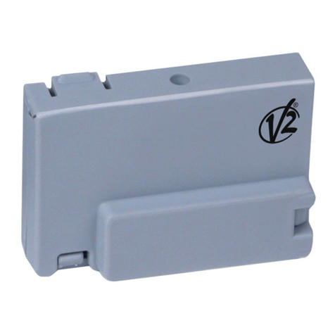
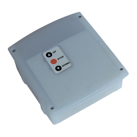
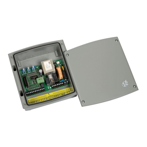
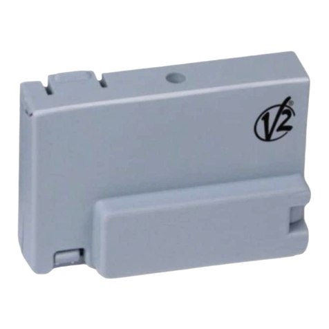
V2 LUX2+ User manual

Value moves the world
ZIS347
IL 383
EDIZ. 08/11/2016
LUX2+
I
MODULO OPZIONALE PER LA
GESTIONE DI LUCI, SEMAFORO O
ELETTROFRENO
GB
OPTIONAL MODULE FOR THE
MANAGEMENT OF LIGHTS,
SEMAPHORE, OR ELECTRICAL
BRAKE
F
MODULE OPTION POUR
LA GESTION DE LUMIÈRES,
SÉMAPHORE OU ÉLECTRO-FREIN
E
MÓDULO OPCIONAL PARA LA
GESTIÓN DE LUCES, SEMÁFORO Y
ELECTROFRENO
P
MÓDULO OPCIONAL PARA A
GESTÃO DE LUZES, SEMÁFORO
OU ELECTROTRAVÃO
D
OPTIONALES MODUL FÜR DIE
STEUERUNG VON BELEUCHTUNG,
AMPEL ODER ELEKTROBREMSE
NL
OPTIONELE MODULE VOOR HET
BEHEER VAN LICHTEN, STOPLICHT
EN ELEKTROREM

Fig. 1

- 3 -
Ch1 Ch2
FUNCTION
M1 M2 M3
12-24 Vdc
Ch1 Ch2
FUNCTION
M1 M2 M3
120-230 Vac
120-230 Vac
N
L
Fig. 2
Fig. 3

ITALIANO
- 4 -
AVVERTENZE IMPORTANTI
Per chiarimenti tecnici o problemi di installazione la V2 SPA
dispone di un servizio di assistenza clienti attivo durante le ore di
ufcio TEL. (+39) 01 72 81 24 11
V2 SPA si riserva il diritto di apportare eventuali modiche al
prodotto senza preavviso; inoltre declina ogni responsabilità per
danni a persone o cose dovuti ad un uso improprio o ad un’errata
installazione.
• Ilpresentemanualediistruzionièdestinatosolamentea
personale tecnico qualicato nel campo delle installazioni di
automazioni.
• Nessunadelleinformazionicontenuteall’internodelmanuale
può essere interessante o utile per l’utilizzatore nale.
• Qualsiasioperazionedimanutenzioneodiprogrammazione
deve essere eseguita esclusiavamente da personale qualicato.
• L’installatoredeveprovvedereall’installazionediundispositivo
(es. interruttore magnetotermico) che assicuri il sezionamento
onnipolare del sistema dalla rete di alimentazione. La normativa
richiede una separazione dei contatti di almeno 3 mm in
ciascunpolo(EN60335-1).
• Unavoltaeffettuatiicollegamentisullamorsettiera,è
necessario mettere delle fascette rispettivamente sui conduttori
a tensione di rete in prossimità della morsettiera e sui
conduttori per i collegamenti delle parti esterne (accessori).
Intalmodo,nelcasodiundistaccoaccidentalediun
conduttore,sievitachelepartiatensionediretepossano
andare in contatto con parti a bassissima tensione di sicurezza.
• Perlaconnessioneditubirigidieessibiliopassacaviutilizzare
raccordiconformialgradodiprotezioneIP55osuperiore.
• Anchel’impiantoelettricoamontedell’automazionedeve
rispondere alle vigenti normative ed essere eseguito a regola
d’arte.
COMPATIBILITÀ
IldispositivoLUX2+ècompatibileconleseguenticentralidi
comando:
CITY1-EVO dallaversione1.0inpoi
CITY1-ECD dallaversione2.4inpoi
CITY2+ dallaversione2.3inpoi
CITY4 dallaversione2.2inpoi
INSTALLAZIONE
LUX2+èunmoduloopzionalechepermettediaumentarele
funzionidellecentraledicomandoV2pilotandodueusciterelè
indipendenti.
Leuscitesonoprogrammabilicon5funzionidifferentitramiteil
menù di programmazione i.Adi della centrale di comando.
mATTENZIONE: l’installazione del dispositivo deve
essere eseguita con l’alimentazione della centrale di
comando scollegata.
AlloggiarelaschedaLUX2+all’internodellascatoladellacentrale
dicomandoecollegareidueconnettoriADI(LUX2+ecentraledi
comando)tramitel’appositocavoatindotazione(Fig.1).
Alimentare la centrale di comando: il led verde presente sul
moduloLUX2+iniziaalampeggiareperindicarecheildispositivo
èattivo.
Effettuare i collegamenti elettrici e procedere con la
programmazione dei parametri di funzionamento.
COLLEGAMENTI ELETTRICI
Sul dispositivo sono presenti 3 morsettiere:
M1 uscitarelè1
M2 uscita per alimentare dispositivi in bassa tensione
M3 uscitarelè2
Se il modulo deve pilotare delle luci in bassa tensione effettuare i
collegamenti come riportato in g. 2.
ATTENZIONE: la tensione fornita dall’uscita M2 dipende
dalla centrale di comando:
• centrali230V-120V g M2=20Vdc-100mA
• centrali24V g M2=12Vdc-100mA
Se il modulo deve pilotare delle luci o altri dispositivi
(es. elettrofreno) a 230V/120V effettuare i collegamenti come
riportato in g. 3.
LED
Sul dispositivo sono presenti 3 led di segnalazione:
FUNCTION:ledverdechelampeggiaquandoLUX2+èinfunzione
Ch1:ledrossochesiaccendequandol’uscitarelè1vienechiusa
Ch2:ledrossochesiaccendequandol’uscitarelè2vienechiusa
USO DEI TASTI PER LA PROGRAMMAZIONE
La programmazione delle funzioni viene eseguita tramite un
appositomenùdicongurazione,accessibileedesplorabile
tramite i 3 tasti h(UP),i(DOWN)eOK posti sotto al display
della centrale.
Diseguitounatabellachedescrivelefunzionideitasti:
Premere e rilasciare il tasto OK / MENU
Premere e rilasciare il tasto h/ UP
Premere e rilasciare il tasto i/ DOWN

ITALIANO
- 5 -
PROGRAMMAZIONE
Avviare la procedura di programmazione sulla centrale di
comando e selezionare il menù i.Adi
1. Selezionare la voce Si e premere OK: il display visualizza LUX
NOTA: per visualizzare la versione rmware del dispositivo
premere il tasto OK
2. Tramite i tasti he iselezionare l’uscita (rEL1 o rEL2) di cui
si vuole programmare la logica di funzionamento e premere
OK
3. Tramite i tasti he iselezionare il parametro che si vuole
programmare:
AUX Canale ausiliario.L’uscitarelèvienecomandatadaun
trasmettitore memorizzato sul canale 4 del ricevitore
innestatonellacentraledicomando.L’uscitarelèpuò
essere programmata con diverse logiche di
funzionamento
LAM Luce di segnalazione lampeggiante.Inbaseallalogica
programmatal’uscitarelèvieneattivatainmodo
intermittente durante le fasi di apertura / chiusura /
pausa del cancello
LUCE Luce di cortesia.Inbaseallalogicaprogrammatailrelè
viene attivato quando la centrale di comando riceve
un comando di START
SEM Semaforo.L’uscitarelèvieneapertaochiusainbase
alle impostazioni delle varie fasi del ciclo di
funzionamento(cancellofermoechiuso,cancello
inapertura,cancelloinchiusura,cancelloinstop,
cancello in pausa)
LSW Segnalazione ne corsa.L’uscitarelèvieneutilizzata
per segnalare il raggiungimento del necorsa delle
ante
FrEn Elettrofreno.L’uscitarelècomandal’elettrofreno
delmotore,aprendosiochiudendosiquandoilmotore
viene azionato.
4. Terminata la programmazione dei parametri selezionare la voce
SAvE per salvare le impostazioni e la voce ESC per uscire dal
menù di programmazione
no
i.Adi
rEL1
LUCE
FrEn
rEL2
SAvE
ESC
LSW
Si
Fv I.0

ITALIANO
- 6 -
CANALE AUSILIARIO
L’uscitarelèvienecomandatadauntrasmettitorememorizzatosul
canale 4 del ricevitore.
L’uscitarelèpuòessereprogrammatacondiverselogichedi
funzionamento:
Mon Monostabile:l’uscitarelèvienechiusapertuttaladurata
della trasmissione del telecomando.
Rilasciandoilpulsantedeltelecomandol’uscitarelèviene
aperta.
biSt Bistabile:lostatodell’uscitarelècommutaadogni
trasmissione del telecomando ricevuta.
tiM Timer 1:l’uscitarelèvienechiusaalricevimento
della trasmissione del telecomando e aperta dopo il
tempo impostato. Se viene ricevuta un’altra trasmissione
durantelafasediattivazione,iltimervienereinizializzato.
toUt Timer 2:l’uscitarelèvienechiusaalricevimento
della trasmissione del telecomando e aperta dopo il
tempo impostato.
Se viene ricevuta un’altra trasmissione durante la fase di
attivazione,l’uscitarelèvieneaperta.
rEL1
biSt
toUt

ITALIANO
- 7 -
LUCE DI SEGNALAZIONE LAMPEGGIANTE
Inbaseallalogicaprogrammatal’uscitarelèvieneazionatain
modo intermittente durante le fasi di apertura e/o chiusura del
cancello.
FLSh Lampeggiante 1:l’uscitarelèvieneazionatainmodo
intermittentea2Hzquandoilcancelloèinmovimento,
comprese eventuali fasi di prelampeggio prima della
partenza
FL.PA Lampeggiante 2:l’uscitarelèvieneazionatainmodo
intermittentea2Hzquandoilcancelloèinmovimento,
durante eventuali fasi di prelampeggio e quando il
cancelloèapertoinpausa
LUCE DI CORTESIA
Inbaseallalogicaprogrammatailrelèvienechiusoquandola
centrale di comando riceve un comando di START
CYCL L’uscitarelèvienechiusaquandolacentralericeveun
comandodiSTART.Quandoilcancellosichiudel’uscita
relèrimaneancorachiusaperiltempoimpostato,quindi
si apre.
W.L. Lampada spia:indicaintemporealelostatodelcancello,
il tipo di lampeggio indica le quattro condizioni possibili:
- CANCELLOFERMOlucespenta
- CANCELLOINPAUSAlaluceèsempreaccesa
- CANCELLOINAPERTURAlalucelampeggia
lentamente (2Hz)
- CANCELLOINCHIUSURAlalucelampeggia
velocemente (4Hz)
tiM L’uscitarelèvienechiusaquandolacentralericeveun
comando di START e aperta dopo il timer impostato.
Se viene ricevuto un altro comando di START durante la
fasediattivazione,iltimervienereinizializzato.
rEL1
FL.PA
FLSh
rEL1 LUCE CYCL

ITALIANO
- 8 -
SEMAFORO
L’uscitarelèvienechiusaoapertainbasealleimpostazionidelle
varie fasi del ciclo di funzionamento.
Ognifasedelciclodifunzionamentoècontraddistintadauna
lettera:
Euscita dal menù
Fcancello fermo e chiuso
Acancello in apertura
Ccancello in chiusura
Scancello in stop (fermo non chiuso)
Pcancello aperto in pausa
Lostatodell’uscitarelèèdenitadalsegmentolampeggiante:
APERTO:lampeggiailsegmentoinBASSO
CHIUSO:lampeggiailsegmentoinALTO
1. Tramite i tasti he iselezionare le varie fasi del ciclo di
funzionamento e tramite il tasto OK selezionare lo stato
dell’uscitarelè
2. Terminate le impostazioni selezionare il menù Eper uscire e
premere il tasto OK per confermare
rEL1 E
F
A
C
S
P
F
A
C
S
P

ITALIANO
- 9 -
SEGNALAZIONE FINE CORSA
L’uscitarelèvieneutilizzatapersegnalareilraggiungimentodel
necorsa delle ante:
oPn1 l’uscitarelèèchiusasel’anta1ècompletamente
aperta
oPn2 l’uscitarelèèchiusaseentrambeleantesono
completamente aperte
CLoS l’uscitarelèèchiusaseentrambeleantesono
completamente chiuse
NOTA: se il cancello ha una sola anta selezionare l’opzione oPn1,
se ne ha 2 selezionare l’opzione oPn2
ELETTROFRENO
L’uscitarelècomandal’elettrofrenodelmotore,aprendosio
chiudendosi quando il motore viene azionato.
nA1 l’uscitarelèèapertaquandoilmotore1èariposo,e
chiusa quando viene azionato
nC1 l’uscitarelèèchiusaquandoilmotore1èariposo,e
aperta quando viene azionato
nA2 l’uscitarelèèapertaquandoilmotore2èariposo,e
chiusa quando viene azionato
nC2 l’uscitarelèèchiusaquandoilmotore2èariposo,e
aperta quando viene azionato
rEL1 LSW oPn 1
oPn 2
CLoS
rEL1 FrEn nA I
nC I
nA 2
nC 2

ENGLISH
- 10 -
IMPORTANT REMARKS
ForanyinstallationproblempleasecontactourCustomerService
atthenumber+39-0172.812411operatingMondaytoFriday
from 8:30 to 12:30 and from 14:00 to 18:00.
V2 has the right to modify the product without previous notice;
it also declines any responsibility to damage or injury to people or
things caused by improper use or wrong installation.
• Thisinstructionmanualisonlyforqualiedtechnicians,who
specialize in installations and automations.
• Thecontentsofthisinstructionmanualdonotconcerntheend
user.
• Everyprogrammingand/oreverymaintenanceserviceshould
be done only by qualied technicians.
• Theinstallermustprovideforadevice(es.magnetotermical
switch) ensuring the omnipolar sectioning of the equipment
from the power supply. The standards require a separation of
thecontactsofatleast3mmineachpole(EN60335-1).
• Aftermakingconnectionsontheterminalboard,useone
hose clamp to x dangerous voltage wires near the terminal
board and another hose clamp to x safety low voltage wires
usedforaccessoriesconnection;thisway,incaseofaccidental
detachmentofaconductingwire,dangerousvoltagepartswill
not come into contact with safety low voltage ones.
• TheplasticcasehasanIP55insulation;toconnectexibleor
rigidpipes,usepipettingshavingthesameinsulationlevel.
• Alsotheautomationupstreamelectricsystemshallcomplywith
thelawsandrulesinforceandbecarriedoutworkmanlike.
COMPATIBILITY
ThedeviceLUX2+iscompatiblewiththefollowingcontrolunits:
CITY1-EVO fromversion1.0onwards
CITY1-ECD fromversion2.4onwards
CITY2+ fromversion2.3onwards
CITY4 fromversion2.2onwards
INSTALLATION
LUX2+isanoptionalmodulethatallowsyoutoincreasethe
capabilities of the V2 control unit controlling two independent
relay outputs.
Theoutputsareprogrammablewith5differentfunctionsviathe
programming menu i.Adi of the control unit.
mATTENTION: the installation of the device must be
performed with the power supply of the control unit
disconnected.
PositionthecardLUX2+insidetheboxofthecontrolunitand
connectthetwoADIconnectors(LUX2+controlunit)viatheat
cablesupplied(Fig.1).
Poweronthecontrolunit:thegreenledontheLUX2+module
beginstoblink,indicatingthatthedeviceisactive.
Perform wiring and proceed with the programming of the
operating parameters.
WIRING
Onthedevicethereare3terminalblocks:
M1 relay 1 output
M2 output for powering low voltage devices
M3 relay 2 output
Ifthemodulehastocontrollowvoltagelights,makethe
connections as shown in gure 2.
ATTENTION: the voltage supplied by the exit M2 depends
on the control unit:
• 230V-120Vcontrolunits g M2=20Vdc-100mA
• 24Vcontrolunits g M2=12Vdc-100mA
Ifthemodulehastocontrollightsorotherdevices
(e.g.electricbrake)with230V/120Vmaketheconnectionsas
shown in gure 3.
LEDS
Onthedevicethereare3signallingleds:
FUNCTION:greenledthatasheswhenLUX2+isactive
Ch1: red led that lights up when the relay 1 output is closed
Ch2: red led that lights up when the relay 2 output is closed
USE OF THE PROGRAMMING KEYS
The programming of the functions is performed by means of a
congurationmenu,accessibleviathe3keysh(UP),i(DOWN)
and OK beneath the display of the control unit.
Belowisatablethatdescribesthefunctionsofthekeys:
PressandreleasethekeyOK / MENU
Pressandreleasethekeyh/ UP
Pressandreleasethekeyi/ DOWN

ENGLISH
- 11 -
PROGRAMMING
Start the programming procedure on the control unit and select
the menu i.Adi
1. Select the item Si and press OK: the display shows LUX
NOTE:todisplaythermwareversionofyourdevice,pressthe
OK key
2. Usingthekeyshand iselect the output (rEL1 or rEL2)
whose operation logic you want to program and press OK
3. Usingthekeyshandiselecttheparameteryouwantto
program:
AUX Auxiliary Channel: the relay output is controlled by a
transmitter stored on channel 4 of the receiver
embedded in the control unit. The relay output can be
programmed with different operation logics
LAM Flashinglight. According to the programmed logic the
relay output is activated in an intermittent manner
during the gate opening / closing / pause stages
LUCE Courtesy light. According to the programmed logic
the relay is activated when the control unit receives a
START command
SEM Semaphore. The relay output is opened or closed
depending on the settings of the various stages of the
operationcycle(gatestoppedandclosed,gate
opening,gateclosing,gatestopped,gatepaused)
LSW Limit switch signal. The relay output is used to signal
the achievement of the limit switches of the leaves.
FrEn Electricbrake. The relay output controls the electric
brakeofthemotor,byopeningorclosingwhenthe
motor is operated.
4. Afterprogrammingtheparameters,selecttheitemSAVE to
save the settings and the item ESC to exit the programming
menu
no
i.Adi
rEL1
LUCE
FrEn
rEL2
SAvE
ESC
LSW
Si
Fv I.0

ENGLISH
- 12 -
AUXILIARY CHANNEL
The relay output is controlled by a transmitter stored on channel 4
of the receiver.
The relay output can be programmed with different operation
logics:
Mon Steady state: the relay output is closed for the duration
of the transmission of the remote control.
Releasing the button on the remote control the relay
output is opened.
biSt Bistable: the state of the relay output switches each time
a transmission is received from the remote control.
tiM Timer 1: the relay output is closed when the transmission
is received from the remote control and opened after the
settime.Ifanothertransmissionisreceivedduring
activation,thetimerisreset.
toUt Timer 2: the relay output is closed when the transmission
is received from the remote control and opened after the
settime.Ifanothertransmissionisreceivedduring
activation,therelayoutputisopened.
rEL1
biSt
toUt

ENGLISH
- 13 -
FLASHING LIGHT
According to the programmed logic the relay output is activated
in an intermittent manner during the opening and/or closing
stages of the gate.
FLSh Flashing1: the relay output is operated intermittently at
2Hzwhenthegateismoving,includinganypre-ashing
stage prior to departure
FL.PA Flashing2: the relay output is operated intermittently at
2Hzwhenthegateismoving,duringanypre-ashing
stageandwithopen,pausedgate
COURTESY LIGHT
According to the programmed logic the relay is closed when the
control unit receives a START command
CYCL The relay output is closed when the control unit receives
aSTARTcommand.Whenthegateclosestherelay
outputstillremainsclosedforthesettime,thenopens.
W.L. Warninglight:indicatestherealtimestatusofthegate,
thetypeofashingindicatesthefourpossible
conditions:
-GATESTOPPEDlightoff
-GATEPAUSEDlightsteadilyon
-GATEOPENINGthelightashesslowly(2Hz)
-GATECLOSINGthelightashesquickly(4Hz)
tiM The relay output is closed when the control unit receives
aSTARTcommandandopenedafterthesettimer.If
anotherSTARTcommandisreceivedduringactivation,
the timer is reset.
rEL1
FL.PA
FLSh
rEL1 LUCE CYCL

ENGLISH
- 14 -
SEMAPHORE
The relay output is closed or opened depending on the settings of
the different stages of the operation cycle.
Each stage of the operation cycle is identied by a letter:
Eexit from the menu
Fgate stopped and closed
Agate opening
Cgate closing
Sgate stopped (stopped not closed)
P open,pausedgate
Thestateoftheoutputrelayisdenedbytheashingsegment:
OPEN:theBOTTOMsegmentashes
CLOSED:theTOPsegmentashes
1. Usingthekeyshand i,selectthedifferentstagesofthe
operation cycle and pressing the OK button select the status of
the relay output
2. Whenyouarenishedwiththesettings,selectthemenuEto
exit and press the OKkeytoconrm
rEL1 E
F
A
C
S
P
F
A
C
S
P

ENGLISH
- 15 -
LIMIT SWITCH SIGNAL
The relay output is used to signal the achievement of the limit
switches of the leaves:
oPn1 The relay output is closed when the leaf 1 is fully open
oPn2 The relay output is closed when both leaves are fully
open
CLoS The relay output is closed when both leaves are fully
close
NOTE:ifthegatehasonlyoneleaf,selecttheoptionoPn1;
ifithas2leaves,selecttheoptionoPn2
ELECTRIC BRAKE
Therelayoutputcontrolstheelectricbrakeofthemotor,by
opening or closing when the motor is operated.
nA1 therelayoutputisopenwhenthemotor1isatrest,
and closed when it is actuated
nC1 therelayoutputisclosedwhenthemotor1isatrest,
and open when it is actuated
nA2 therelayoutputisopenwhenthemotor2isatrest,
and closed when it is actuated
nC2 therelayoutputisclosedwhenthemotor2isatrest,
and open when it is actuated
rEL1 LSW oPn 1
oPn 2
CLoS
rEL1 FrEn nA I
nC I
nA 2
nC 2

FRANÇAIS
- 16 -
CONSEILS IMPORTANTS
Pourtoutprécisiontechniqueouproblèmed’installationV2
dispose d’un Service Clients à Votre disposition du lundi au
vendredi de 8:30 à 12:30 et de 14:00 heures à 18:00 heures au
numéro+39-0172.812411
V2 se réserve le droit d’apporter d’éventuelles modications au
produit sans préavis; elle décline en outre toute responsabilité
pour tous types de dommages aux personnes ou aux choses dus à
une utilisation imporopre ou à une mauvaise installation.
• Cemanueld’instructionestdestinéàdestechniciensqualiés
dans le domain des automatismes.
• Aucunedesinformationscontenuesdanscelivretpourraêtre
utile pour le particulier.
• Tousoperationsdemaintenanceouprogramationdoiventêtre
faites à travers de techniciens qualiés.
• L’installateurdoitpourvoiràl’installationd’undispositif
(ex. interrupteur magnétothermique) qui assure la coupure
omnipolaire de l’équipement du réseau d’alimentation.
La norme requiert une séparation des contacts d’au moins
3mmpourchaquepôle(EN60335-1).
• Quandonaeffectuélesbranchementsàlaborniere,ilfaut
mettre des bandes sur les conducteurs à tension qui se
trouvent en proximité de la borniere et sur les conducteurs
pour le branchement des parties externes (accessoires).
Decettemaniere,encasdedétachementd’unconducteur,on
évite que les partie en tension puissent aller en contact avec les
parties à faible tension de sécurité.
• Pourlaconnexiondetubesrigidesouexiblesutiliserdes
raccordementspossédantleIP55niveaudeprotection.
• Mêmel’installationélectriqueouonbranchel’automatisme
doitrépondreauxnormesenvigueuretêtrefaitàrèglesde
l’art.
COMPATIBILITÉ
LedispositifLUX2+estcompatibleaveclescentralesde
commande suivantes :
CITY1-EVO àpartirdelaversion1.0etsuivantes
CITY1-ECD àpartirdelaversion2.4etsuivantes
CITY2+ àpartirdelaversion2.3etsuivantes
CITY4 àpartirdelaversion2.2etsuivantes
INSTALLATION
LUX2+estunmoduleenoptionquipermetd’augmenterles
fonctions des centrales de commande V2 en pilotant deux sorties
relais indépendantes.
Lessortiessontprogrammablesavec5fonctionsdifférentes
au moyen du menu de programmation i.Adi de la centrale de
commande.
mATTENTION : l’installation du dispositif doit être
effectuée avec l’alimentation de la centrale de commande
débranchée.
LogerlacarteLUX2+àl’intérieurdelaboîtedelacentralede
commandeetbrancherlesdeuxconnecteursADI(LUX2+et
centraledecommande)àl’aideducâbleplatfourni(Fig.1).
Alimenter la centrale de commande : le led vert présent sur
lemoduleLUX2+commenceàclignoterpourindiquerquele
dispositif est activé.
Effectuer les branchements électriques et procéder à la
programmationdesparamètresdefonctionnement.
BRANCHEMENTS ÉLECTRIQUES
Surledispositif,gurent3boîtesàbornes:
M1 sortie relais 1
M2 sortie pour alimenter les dispositifs à basse tension
M3 sortie relais 2
Silemoduledoitpiloterdeslumièresàbassepression,effectuer
les branchement comme indiqué à la g. 2.
ATTENTION : la tension fournie par la sortieM2 dépend de la
centrale de commande:
• centrales230V-120V g M2=20Vcc-100mA
• centrales24V g M2=12Vcc-100mA
Silemoduledoitpiloterdeslumièresouautresdispositifs
(ex.électro-frein)à230V/120V,effectuerlesbranchements
comme indiqué à la g. 3.
LED
Surledispositif,gurent3leddesignalisation:
FUNCTION:ledvertquiclignotequandLUX2+estenmarche
Ch1: led rouge qui s’allume quand la sortie relais 1 est fermée
Ch2: led rouge qui s’allume quand la sortie relais 2 est fermée
UTILISATION DES TOUCHES POUR LA
PROGRAMMATION
La programmation des fonctions est effectuée à l’aide d’un menu
decongurationspécique,accessibleetexplorableaumoyen
des 3 touches h(UP),i(DOWN)etOK situés sous le display de
la centrale.
Ci-aprèsuntableauquidécritlesfonctionsdestouches:
Enfoncer et relâcher la touche OK / MENU
Enfoncer et relâcher la touche h/ UP
Enfoncer et relâcher la touche i/ DOWN
FRANÇAIS
- 17 -
PROGRAMMATION
Démarrerlaprocéduredeprogrammationsurlacentralede
commande et sélectionner le i.Adi
1. Sélectionner la rubrique Si et appuyer sur OK : le display
afchera LUX
REMARQUE : pour afcher la version micrologiciel du
dispositif,appuyersurlatoucheOK
2. À l’aide des touches het i,sélectionnerlasortie(rEL1
ou rEL2) dont on veut programmer la logique de
fonctionnement et appuyer sur OK
3. À l’aide des touches het i,sélectionnerleparamètrequel’on
veut programmer :
AUX Canal auxiliaire : la sortie relais est commandée par un
émetteur mémorisé sur le canal 4 du récepteur greffé
dans la centrale de commande. La sortie relais peut
êtreprogramméeavecdifférenteslogiquesde
fonctionnement
LAM Lumièredesignalisationclignotante.Enfonctiondela
logiqueprogrammée,lasortierelaisestactivéede
manièreintermittentependantlesphasesd’ouverture
/ fermeture / pause de la grille
LUCE Lumièredecourtoisie. En fonction de la logique
programmée,lerelaisestactivéquandlacentralede
commande reçoit une commande de START
SEM Sémaphore. La sortie relais est ouverte ou fermée
en fonction des réglages des différentes phases du
cycledefonctionnement(grilleàl’arrêtetfermée,
grilleenouverture,grilleenfermeture,grilleenarrêt,
grille en pause)
LSW Indication de n de course.Onutiliselasortierelais
pour indiquer que le n de course des vantaux a été
rejoint:
FrEn Electro-frein.Lasortierelaiscommandel’électro-frein
dumoteur,ens’ouvrantouensefermantquandle
moteur est actionné.
4. Laprogrammationdesparamètresterminée,sélectionner
SAVE pour sauvegarder les congurations et ESC pour sortir
du menu de programmation
no
i.Adi
rEL1
LUCE
FrEn
rEL2
SAvE
ESC
LSW
Si
Fv I.0

FRANÇAIS
- 18 -
CANAL AUXILIAIRE
La sortie relais est commandée par un émetteur mémorisé sur le
canal 4 du récepteur.
Lasortierelaispeutêtreprogramméeavecdifférenteslogiquesde
fonctionnement :
Mon Monostable : la sortie relais est fermée pendant toute la
durée de la transmission de la télécommande.
Enrelâchantleboutondelatélécommande,lasortie
relais est ouverte.
biSt Bistable : l’état de la sortie relais commute à chaque
transmission de la télécommande reçue.
tiM Temporisateur 1 : la sortie relais est fermée à la réception
de la transmission de la télécommande et ouverte
pendant le temps conguré. Si une autre transmission
estreçuependantlaphased’activation,letemporisateur
est réinitialisé.
toUt Temporisateur 2 : la sortie relais est fermée à la réception
delatransmissiondelatélécommandeetouverteaprès
le temps conguré. Si une autre transmission est reçue
pendantlaphased’activation,lasortierelaisestouverte.
rEL1
biSt
toUt

FRANÇAIS
- 19 -
LUMIÈRE DE SIGNALISATION CLIGNOTANTE
Enfonctiondelalogiqueprogrammée,lasortierelaisest
actionnéedemanièreintermittentependantlesphases
d’ouverture et/ou de fermeture de la grille.
FLSh Clignotant 1:lasortierelaisestactionnéedemanière
intermittenteà2Hzquandlagrilleestenmouvement,
ycomprisleséventuellesphasesdepré-clignotement
avant le départ
FL.PA Clignotant 2:lasortierelaisestactionnéedemanière
intermittenteà2Hzquandlagrilleestenmouvement,
pendantleséventuellesphasesdepré-clignotementet
quand la grille est ouverte en pause
LUMIÈRE DE COURTOISIE
Enfonctiondelalogiqueprogrammée,lerelaisestferméquand
la centrale de commande reçoit une commande de START
CYCL La sortie relais est fermée quand la centrale reçoit une
commandedeSTART.Quandlagrilleseferme,lasortie
relais reste encore fermée pendant le temps conguré et
puis s’ouvre.
W.L. Voyant:indiqueentempsréell’étatdelagrille,letype
de clignotement indique les quatre conditions possibles :
- GRILLEÀL’ARRÊTlumièreéteinte
- GRILLEENPAUSElalumièreesttoujoursallumée
- GRILLEENOUVERTURElalumièreclignotelentement
(2Hz)
- GRILLEENFERMETURElalumièreclignoterapidement
(4Hz)
tiM La sortie relais est fermée quand la centrale reçoit une
commandedeSTARTetouverteaprèsquele
temporisateur ait été conguré. Si une autre commande
deSTARTestreçuependantlaphased’activation,le
temporisateur est réinitialisé.
rEL1
FL.PA
FLSh
rEL1 LUCE CYCL

FRANÇAIS
- 20 -
FEU
La sortie relais est fermée ou ouverte en fonction des réglages des
différentes phases du cycle de fonctionnement.
Chaque phase du cycle de fonctionnement se distingue par une
lettre :
Esortie du menu
F grilleàl’arrêtetfermée
Agrille en ouverture
Cgrille en fermeture
S grilleenarrêt(arrêtéenonfermée)
Pgrille ouverte en pause
L’état de la sortie relais est dénie par le segment clignotant :
OUVERT:lesegmentenBASclignote
FERMÉ:lesegmentenHAUTclignote
1. A l’aide des touches het i,sélectionnerlesdifférentesphases
du cycle de fonctionnement et à l’aide de la touche OK,
sélectionner l’état de la sortie relais
2. Lesréglagesterminés,sélectionnerlemenuEpour sortir et
appuyer sur la touche OK pour conrmer
rEL1 E
F
A
C
S
P
F
A
C
S
P
Table of contents
Languages:
Other V2 Control Unit manuals