manuals.online logo
Brands
  1. Home
  2. •
  3. Brands
  4. •
  5. Mora
  6. •
  7. Plumbing Product
  8. •
  9. Mora Temp Duo 72 20 00 User manual

Mora Temp Duo 72 20 00 User manual

72 20 00, 72 20 01,
72 20 02, 72 20 03,
72 20 04, 72 20 05
ASSEMBLY INSTRUCTIONS
General
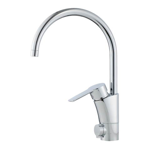
MORA TEMP DUO - TWO MIXERSINONE!
• MoraTempDuoisacombinationofastandardkitchenorwashbasinmixerand
a sensor controlled tap. Using the lever the Mora Temp Duo works exactly as
any other ordinary mixer. But with the sensor function you get a non contact
function by holding your hands in front of the sensor eyes.
• When installing MoraTemp Duo in rooms where there is a periodic risk of
freezing, the fittings must be drained of water, otherwise there is a risk of the
tap being damaged through freezing.
• The control box must not be washed by high-pressure jet cleaning.
• The sensor part of the tap is fitted with automatic shut off after 24 seconds of
use (adjustable up to 48 sec). In order for the tap to start again the ”obstacle”
oryourhandsmustberemovedfrominfrontofthesensoreyesandthenmoved
back again. This is a safety feature to prevent flooding if an object were to be
placed in front of the sensor eyes.
• Before connection is made, the incoming water pipes must be flushed.
NOTE: If the red indication lamp is flashing or lights without the tap being used,
the battery voltage is too low, and the batteries must be replaced.
When the batteries have been removed and then replaced, the
RESET button on the circuit board must always be pressed in for a brief moment
to reset the electronics.
Spent products can always be sent to MORA ARMATUR AB
for recycling.
Assembly
1. Place the mixer in the hole, rec. hole dim 35mm (max 37mm - min 32mm),
and attach using the support washer and nut.
2. Remove the control cover, pull out the circuit board and make the neces-
sary changes to flush time and sensor distance. (see diagram A). Mount
the batteries, attach the sensor cable (the cable between the sensor eyes
and control box) on the circuit board, press the RESET button on the circuit
board and put back the cover. On AC operation: select AC instead of DC on
the circuit board, reset the transformer to 12V operation. Connect to circuit
board. Press RESET.
3. Connect the valve block to the mixer’s connection pipe (remember the sup-
port sleeves in the connection pipe) and to incoming hot and cold water. If the
mixer has an outlet for connecting a dishwasher, connect the dishwasher’s
connection hose to the mixer’s outlet pipe.
4. Assemble the solenoid valve with the ball valve in the control box. Then attach
the ball valve to the valve plate. Do not forget the filter/packing. If there is a
limited space against the drain trap, the enclosed elbow can be attached in
between to angle the control box 90° out of line.
5. Then fit the connection hose between the outlet on the solenoid valve and the
mixer’s connection for incoming hot water.
6. The mixer valve built into the valve block only supplies the tap with water
during sensor operation. This is set to give hot water on delivery; the exact
temperature and flow can be adjusted using the adjuster screw (see diagram
B).
NOTE:Ifonly coldwaterisrequired(100%)fromthetapduringsensoroperation,
the accompanying cold water plug must be fitted (see diagram C).
7. Turn on the water.
8. Test the activation distance. If the activation radius of the sensor is too
short/long, this can be adjusted using switch no. 6 (rough adjustment) and
the adjuster screw (fine adjustment), see diagram A.
NOTE: Be careful - only small adjustments to the screw are needed to change
the activation distance.
9. Check that the after flush time and the maximum flush time are satisfactory,
otherwise adjust these on the circuit board in the control box. Hot water in Cold water in
Valve block
Connection
hose for
mixed water
Control box with solenoid valve
Sensor eyes
Lever
Indication lamp
Supporting
sleeves
Dirt filter with
gasket
Supporting
sleeves
NOTE: Requires Cu-pipe Ø 12x1
Ball valve
Mora Armatur AB
Box 440
SE-792 27 MORA
SWEDEN
www.moraarmatur.se
INSTRUCTION
1
Mora Temp Duo
07.04. MA nr 1001032
1 2 3
ON ON ON
ON ON OFF
ON OFF ON
ON OFF OFF
OFF ON ON
OFF ON OFF
OFF OFF ON
OFF OFF OFF
After flush time
1 sec.
2 sec.
3 sec.
4 sec.
5 sec.
6 sec.
7 sec.
8 sec
.
*
* normal setting
Contact for connection of
batterycassette(red/black
cable).
Distance settings (fin adjust. with screw in box)
6
0 cm - 15 cm ON
15 cm - 45 cm OFF
Max flush time
none
12 sec.
24 sec.
48 sec.
*
4 5
ON ON
ON OFF
OFF ON
OFF OFF
Electronics settings:
002K0104
500 OL
(RESET)
1 2 3 4 5 6
CTS 208-6 T946
O
N
AC<->DC
Settings breaker 1-3: After
flush time, 4-5: Maximum
flush period, 6: Sensor dis-
tance, rough adjustment. Self-test of
electronics.
Contact for connection to
transformer (extra acces-
sory).
Contactforconnectionof
tap sensor eyes.
Contact for connection
to solenoid valve (blue/
orange cable)
Indicationlamp,
green.
Indicationlamp,
red.
Change-over switch
between battery and
mains. Mode DC =
battery operation.
Name MA-nr
Control box 72 93 43
Circuit board 72 93 42
Sensor eyes with cable 72 93 18
Valve block 72 93 24
Solenoid coil 72 93 46
Connection hose 70 97 17
Membrane disk 72 92 27
Transformer for mains 72 92 30
Cable to transformer 72 92 29
Angle element G1/2 63 04 71
Ball valve 63 21 51
002K0104
500 OL
(RESET)
1 2 3 4 5 6
CTS 208-6 T946
O
N
AC<->DC
Control box
Circuit board
Valve block
Solenoid coil
Membrane disk
Transformer for mains
Sat at 6V on delivery.
Adjustable to 12V
Cable to transformer
Angle element G1/2 Sensor eyes with cableConnection hose
Spare Part number
SETTINGS AND CONNECTIONS
+
-
* normal setting
*
SPARE PARTS
Diagram 1
Ball valve
INSTRUCTION
2
07.04. MA nr 1001032
4 5
ON ON
ON OFF
OFF ON
OFF OFF
Valve block with mixer valve
and throttle screw
Connection to
mixer; Ø10mm
Connection to incoming
water Ø12mm
Connection to
solenoid valve
You can adjust the temperature
usingaslottedscrewdriver;clock-
wise for hotter and anticlockwise
for colder
The flow during sensor operation
is adjusted using the flow knob
(8mmkeyhandle).Clockwiseturning
givesalowerflow,andanticlockwise
increases the flow
Temperature and flow setting
Only cold water for sensor operation
The temperature of the water during sensor operation is determined by a mixing
valve that is built in to the valve block. You can use the temperature screw to
produce fairly cold water, although not 100 % cold water, which sometimes may
be required if you need the water for preparing food etc.
In order to always have 100 % cold water during sensor operation a cold water
plug must be fitted. Remove the cover on the cold water side, and fit the cover and
spring from the hot water side. On the hot water side the ”cold water plug” must
be fitted (included). To do this you only need a 3mm Allen key. When the plug has
been fitted, the tap will always give 100 % cold water during sensor operation.
The function of the mixer valve has been totally blocked, and the water that the
tap now produces during sensor operation can be used as drinking water and for
food preparation.
CW
HW
CW
HW
Removing the sensor eyes
Remove the sensor cable contact in the control box. Pull
out the sensor pack from the foot of the mixer using a small
screwdriver or the tip of a knife. Work the cable and contact
through the hole. Depending on how big the assembly hole
in the bench top is, you may need to remove the mixer and
lift it up a few centimetres to get at the contact.
Reassemble the new sensor pack in the reverse order.
CW-side HW-side
The cover
The cover and spring
insidemust be movedto
the cold water side
The cold water plug is to
befittedonthe hot water
side where the cover and
springarelocatedindeli-
very configuration.
CW-plug
SETTINGS AND CONNECTIONS
Diagram 2
Diagram 3
INSTRUCTION
3
07.04. MA nr 1001032
TROUBLESHOOTING AND CORRECTIVE MEASURES FOR THE SENSOR FUNCTION
Sensor function
gives no water
Transformer fault set, AC not
selected and activated on the
circuit board.
The water is shut off
Poor or batteries turned the
wrong way
Sensor distance too short
The solenoid valve is not
working
Dirt in the solenoid valve
Inlet filter clogged
Fault in the electronics
Check that the transformer is set to 12V. And
that the circuit board has AC selected.
Check the water connection
Check the batteries, 4 ea R6 á 1.5 volt, which
must be mounted according to the instructions
in the battery compartment
Try moving your hand closer to the sensor eyes
Activate the sensor eyes and listen for a click-
ing sound
see above
Examine the inlet filter mounted between the
solenoid valve and valve block
Conduct a ”self-test” as described above
Set the Transformer to 12V. Select AC.
Press RESET.
Open any shut offs
Replace batteries, or correct the position
of the battery. NOTE: Use alkaline bat-
teries!
Adjust the sensor gap
If you hear no sound: Replace the
solenoid coil or if necessary the entire
solenoid valve
If you hear a clicking sound - clean the
solenoid valve or replace the membrane
disk, see figure below
Clean the inlet filter
Replace the sensor eyes or circuit board
POSSIBLECAUSE TROUBLESHOOTING CORRECTIVEMEASUREPROBLEMS
The tap will not
turn off
Before additional tests can be made, establish whether the fault is electrical or mechanical by disconnecting the batteries.
If the tap shuts off with disconnected current, the fault is electrical. If the tap continues to run there is a mechanical fault.
Mechanical fault - dirt in the
solenoid valve
Electrical fault - the elec-
tronics prevent the solenoid
valve from shutting off
-
Conduct a ”self-test” as described above
Dismantle the solenoid valve for clea-
ning, see figure below
Replace the sensor eyes or circuit board
Dirt in the solenoid valve, or
leaky membrane disk
Screw apart the solenoid valve and look for dirt
and check the membrane disk
Clean and where necessary replace the
membrane disk, see figure below
The tap is dripping
The sensor distance is too far - Adjust the sensor distance to about 5
cm in front of the sensor eyes
The tap opens/
shuts off con-
stantly The sensor eyes are defective The sensor distance setting is not reacting Replace the sensor eyes
Normal function
When activating the sensor function, a red flashing light is to be visible on the indication lamp (under the sensor eyes) just when the flow
starts.Test:
MoraTemp Duo has a built-in function for self-testing in the electronics unit. This is what you do: Open the control box cover and pull out the
circuit board. Press the ”RESET” button briefly. The result should then be a red flashing light both from the indication lamp on the tap and from
the circuit board, a clicking sound from the solenoid valve and the tap should open. Then a green flashing light on the circuit board, clicking
from the solenoid valve, the tap shuts off, then two red flashes from the indication lamp and on the circuit board. This test confirms that the
electronics are OK.
Clean the
holes when
necessary
Membrane
disk
Maintenance and cleaning
Themaintenancenormallyrequiredinvolves,forthemostpart,keepingthesensor
eyes clean. Use no abrasive cleaning agent or strong substances that might
damage the lenses. If the water contains a lot of particles and dirt, you might
sometimes need to remove and clean the solenoid valve’s water affected parts,
and the dirt filter that is fitted between the valve block and solenoid valve. Be
particularly careful with the small holes in the membrane disk and the surfaces
to which they seal.
Strong sunlight aimed directly at the sensor eyes may also disturb the function.
Theinterval betweenbatteryreplacementvariesalot,but fornormaluse working
life should be year or so.
Always use alkaline batteries for best performance.
When assem-
bling check
that this hole is
correctly aligned
with the cor-
responding hole
on the solenoid
valve.
Reset to AC but
nothing is working
4
07.04. MA nr 1001032
INSTRUCTION
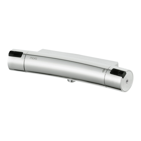
This manual suits for next models

5

Other Mora Plumbing Product manuals

Mora Rexx Family S5 User manual

Mora

Mora Rexx Family S5 User manual

Mora Cera 702320.DA User manual

Mora

Mora Cera 702320.DA User manual

Mora Cera 702358 User manual

Mora

Mora Cera 702358 User manual

Mora MMIX T5 730000M User manual

Mora

Mora MMIX T5 730000M User manual

Mora TRONIC COMPACT WMS Technical specifications

Mora

Mora TRONIC COMPACT WMS Technical specifications

Mora Cera 702245 User manual

Mora

Mora Cera 702245 User manual

Mora Mega Pool User manual

Mora

Mora Mega Pool User manual

Mora MMIX Tronic User manual

Mora

Mora MMIX Tronic User manual

Mora Rexx TILLVAL User manual

Mora

Mora Rexx TILLVAL User manual

Mora Classic Series User manual

Mora

Mora Classic Series User manual

Mora MMIX Series User manual

Mora

Mora MMIX Series User manual

Mora Cera User manual

Mora

Mora Cera User manual

Mora Temp User manual

Mora

Mora Temp User manual

Mora MMIX W1 User manual

Mora

Mora MMIX W1 User manual

Mora MMIX Safe 731100.SA User manual

Mora

Mora MMIX Safe 731100.SA User manual

Mora Rexx User manual

Mora

Mora Rexx User manual

Mora Cera B5 243000.CAM User manual

Mora

Mora Cera B5 243000.CAM User manual

Mora MMIX MO731101.SA User manual

Mora

Mora MMIX MO731101.SA User manual

Mora MMIX User manual

Mora

Mora MMIX User manual

Mora MMIX 40 93 95.AE User manual

Mora

Mora MMIX 40 93 95.AE User manual

Mora Styxx 722030 User manual

Mora

Mora Styxx 722030 User manual

Mora MMIX MA 73 01 00 Series Technical specifications

Mora

Mora MMIX MA 73 01 00 Series Technical specifications

Mora Rexx T5 User manual

Mora

Mora Rexx T5 User manual

Mora Cera User manual

Mora

Mora Cera User manual

Popular Plumbing Product manuals by other brands

Hans Grohe Talis M52 260 1jet Instructions for use/assembly instructions

Hans Grohe

Hans Grohe Talis M52 260 1jet Instructions for use/assembly instructions

American Standard Exposed Yoke Wall-Mount Utility Faucet... repair parts

American Standard

American Standard Exposed Yoke Wall-Mount Utility Faucet... repair parts

Spectrum Brands Pfister Jaida LF-042-JD Quick installation guide

Spectrum Brands

Spectrum Brands Pfister Jaida LF-042-JD Quick installation guide

KWC ACXT2005 Installation and operating instructions

KWC

KWC ACXT2005 Installation and operating instructions

T&S B-1450-01 Installation and maintenance instructions

T&S

T&S B-1450-01 Installation and maintenance instructions

Hansgrohe Axor Citterio 39850 Series Instructions for use/assembly instructions

Hansgrohe Axor

Hansgrohe Axor Citterio 39850 Series Instructions for use/assembly instructions

resideo Braukman F74CS installation instructions

resideo

resideo Braukman F74CS installation instructions

CRISTINA WX508 installation instructions

CRISTINA

CRISTINA WX508 installation instructions

Abode BromptonBridge 5662 manual

Abode

Abode BromptonBridge 5662 manual

Hans Grohe Metropol 32540 Series Instructions for use/assembly instructions

Hans Grohe

Hans Grohe Metropol 32540 Series Instructions for use/assembly instructions

Westlake GVS-65 installation guide

Westlake

Westlake GVS-65 installation guide

Symmons Identity SLW6712PP Operation & maintenance manual

Symmons

Symmons Identity SLW6712PP Operation & maintenance manual

Hans Grohe Logis Loop 71244000 Instructions for use/assembly instructions

Hans Grohe

Hans Grohe Logis Loop 71244000 Instructions for use/assembly instructions

Homewerks Worldwide 3210-151-CH-BC-Z quick start guide

Homewerks Worldwide

Homewerks Worldwide 3210-151-CH-BC-Z quick start guide

Grohe Geneva 25 054 manual

Grohe

Grohe Geneva 25 054 manual

Hans Grohe Novus 71324000 Assembly instructions

Hans Grohe

Hans Grohe Novus 71324000 Assembly instructions

Hans Grohe Focus M42 220 1jet 71802 Series Instructions for use/assembly instructions

Hans Grohe

Hans Grohe Focus M42 220 1jet 71802 Series Instructions for use/assembly instructions

Grohe Grohtherm 2000 installation instructions

Grohe

Grohe Grohtherm 2000 installation instructions

manuals.online logo
manuals.online logoBrands
  • About & Mission
  • Contact us
  • Privacy Policy
  • Terms and Conditions

Copyright 2025 Manuals.Online. All Rights Reserved.