MSA Ultra Elite Responder Operating instructions

TAL 012 (L) Rev. 1 © MSA 2010 Prnt. Spec. 100000053 9(I) Mat. 10096395
Doc. 10096395
Ultra Elite®
Responder®
Facepiece
MAINTENANCE AND REPAIR

ULTRA ELITE RES ONDER FACE IECE
P/N
Description
10093924
Small
10093923
Medium
10093925
Large
10093027
Small, CC-ready*
10093026
Medium, CC-ready*
10093028
Large, CC-ready*
10093930
Small, w/ UID, CC- ready*
10093929
Medium, w/ UID, CC- ready*
10093931
Large, w/ UID, CC- ready*
10094029
Small, w/ UID, CC- ready*
10094028
Medium, w/ UID, CC- ready*
Ultra Elite Responder Facepiece
10094030
Large, w/ UID, CC- ready*
304746
External Drinking Tube (Pack of 5)
10082503
Drinking Tube Connector
10093935
304749
Drinking Tube Coupling
10093937
Internal Drinking Tube
10093919
Lens Plug (Pack of 5)
10093920
Component Housing Cover
10093921
Nosecup, Medium
10093922
Nosecup, Large
10093932
Lens Cover Label (Pack of 10)
10093933
Lens Assembly
10025295
Lens Receptacle Inhalation Valve Disc
10093934
Cover Assembly
10093936
Component Housing Assembly, CC-ready*
10093938
Component Housing Assembly, CC-ready*
10024076
ClearCommand Communication
System Microphone
10024077
ClearCommand Communication
System Mounting Bracket
10093945
#6 – 32 Nut(Pack of 10)
10093939
Pneumatic Nut (Pack of 5)
10093940
Pneumatic Assembly
10093941
Pneumatic Piston
10093942
Pneumatic Spring (Pack of 5)
10093943
Pneumatic Retainer (Pack of 5)
10093944
Silicone O-Ring (Pack of 20)
10086032
Pneumatic Nut Special Tool
* Includes ClearCommand Communication System Microphone
Parts ListReplacement Kits
Item P/N Description
1 Ultra Elite Responder Facepiece
2 10093933 Lens Assembly
3 10025295 Lens Receptacle Inhalation Valve Disc
4 10082477 O-Ring
5 10093919 Lens Port Plug
8 804805 Lower Lens Ring
6 804804 Upper Lens Ring
7 10093945 Screw
9 10083233 HUD Bracket
10 10031102
10031105
Speed
Replacement Pull Straps
-ON®Harness Assembly
11 494297 Buckles (3 Req’d.)
12 804807 Buckle Assembly with D-Ring (2 Req’d.)
13 10024077 ClearCommand Communication System
Mounting Bracket
14 10034748 Screw
15 10023505 Gray Speaking Diaphragm Retainer
(ClearCommand Communication System)
15a 804808 Black Speaking Diaphragm Retainer
16 10093937 Internal Drinking Tube
17 804809 Speaking Diaphragm
17a 10024076 ClearCommand Communication System
Microphone
18 10093921 Nosecup, Medium
10093922 Nosecup, Large
19 10093936 CC-ready*
10093938 Component Housing
20 814459 Exhalation Valve
21 804813 Inhalation Valve Disc
22 805011 Valve Spider
23 10033115 Adapter Assembly
24 10082503 Drinking Tube Connector
25 304746 External Drinking Tube
26 304749 Drinking Tube Coupling
27 804811 Component Housing Ring
28 490133 Exhalation Valve Spring
29 10093943 Pneumatic Retainer
30 10093942 Pneumatic Spring
31 10093941 Pneumatic Piston
32 10093994 O-Ring
33 10093940 Pneumatic Assembly
34 10082508 Retaining Ring
35 10093939 Pneumatic Nut
36
10093920 Component Housing Cover
10093934 Component Housing Cover w/ UID
10095079 Component Housing Cover
37 10082500 #6 x 32 Nut
38 804829 Neck strap
39 10093932 Lens Cover Label
604070 Christo-Lube
10086032 Pneumatic Nut Special Tool
* Includes ClearCommand Communication System Microphone
2
TAL 012 (L) Rev. 1 - 10096395

3TAL 012 (L) Rev. 1 - 10096395
ULTRA ELITE RES ONDER FACE IECE
1
2
6
7
8
9
10
12
11
13
14
17a
18
19
20
21
22
23
24
25
27
28
29
30
31
32
33
34
7
16
15
32
35
37
36
3
5
38
39
26
4
17
15a
Christo-Lube
Christo-Lube
Exploded View

ULTRA ELITE RES ONDER FACE IECE
DISASSEMBLY
Removing the SpeeD-ON Head Harness
The center strap of the SpeeD-ON head Harness is stitched
permanently to the buckle. To replace the harness:
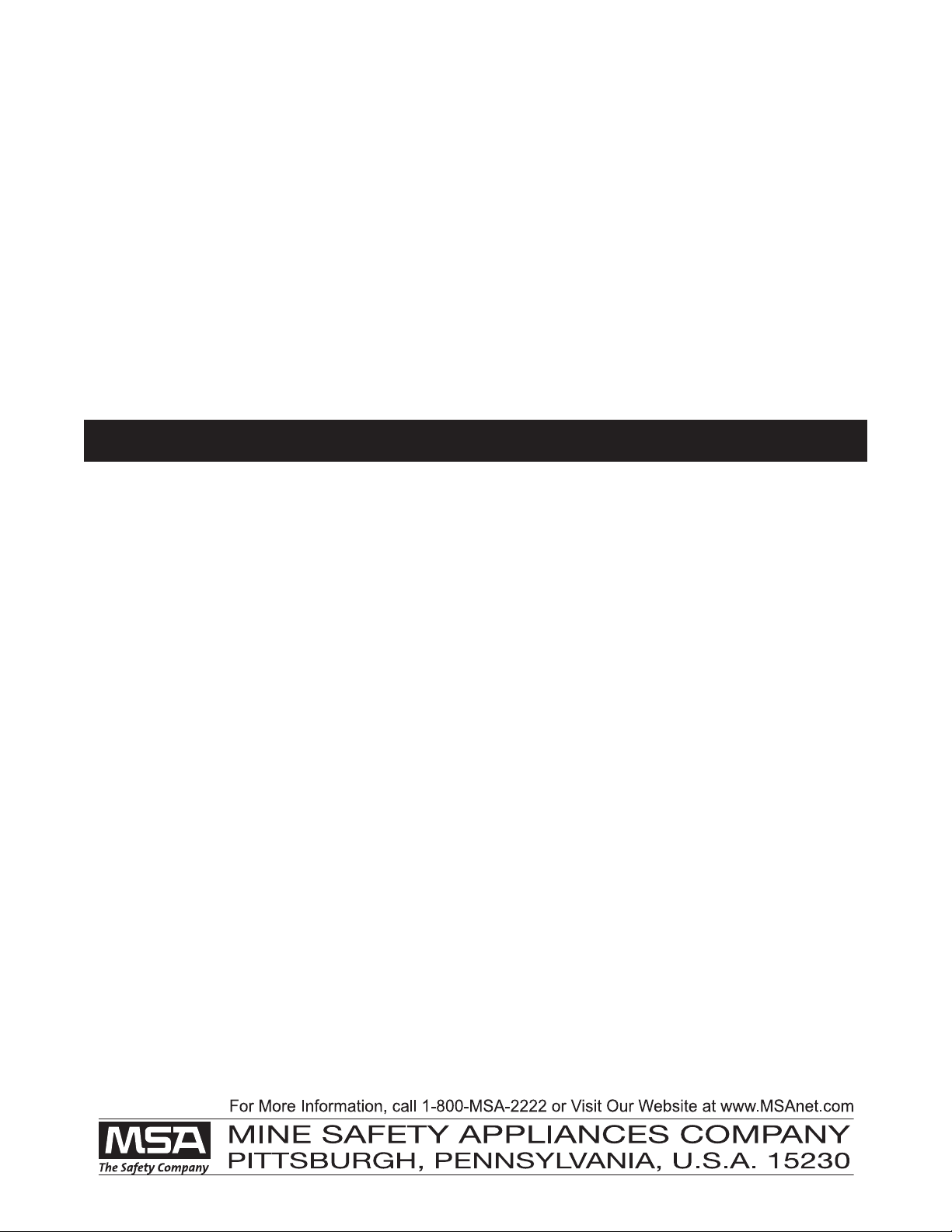
1. Remove the center strap and buckle.
a. Grasp the facepiece lug with one hand and the
buckle with the other.
b. Lift the metal buckle
while stretching the
facepiece lug.
2. Remove the temple and jaw straps.
a. Extend each strap so that the end tab is at the
buckle.
b. Unlace the straps.
Note: To remove the SpeeD-ON Head harness with
buckles, repeat step 1 on each buckle.
Removing the M7 HUD Mounting Bracket
Note: Clean and disinfect the facepiece before removing
and disassembling the component housing. (See
Cleaning and Disinfecting for instructions.)
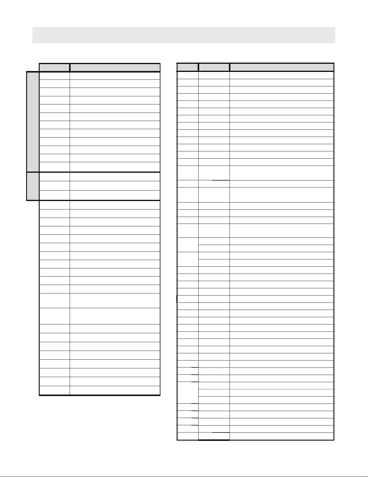
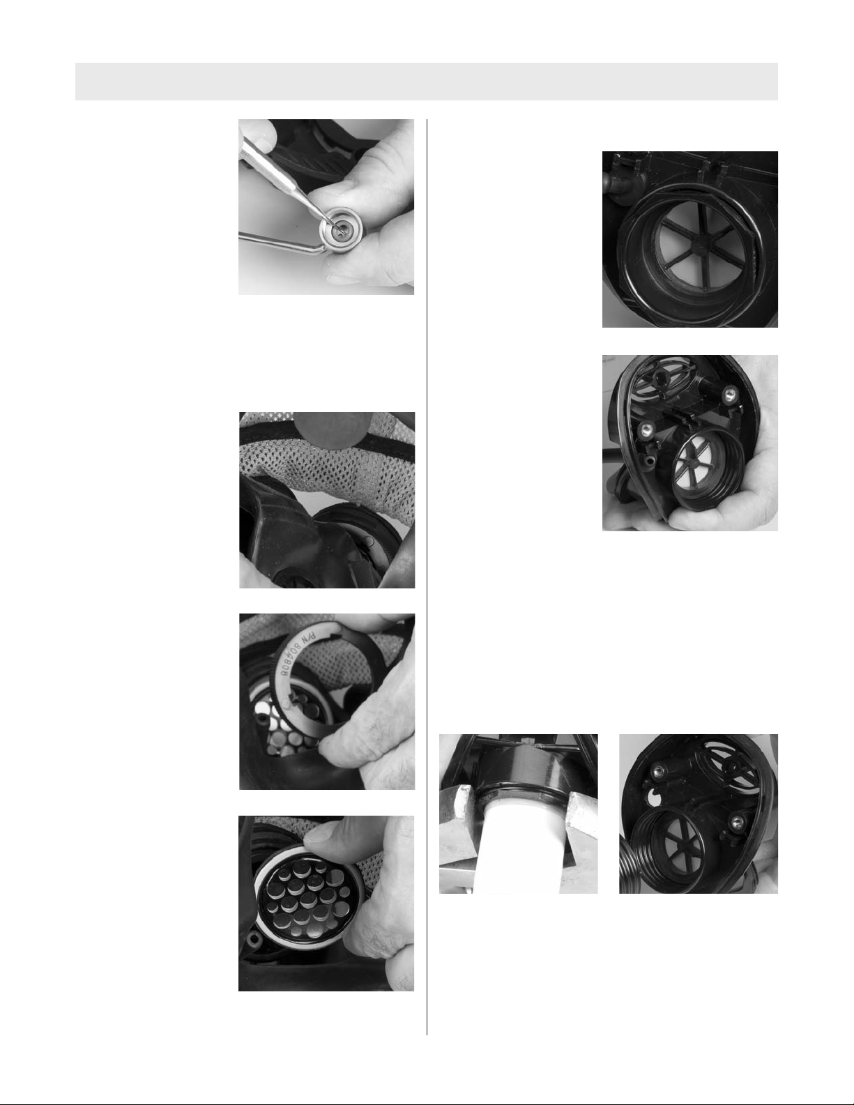
1. Remove the screws
from the lens rings.
2. Remove the component housing cover. (See
Removing the Component Housing Cover for
instructions.)
4
TAL 012 (L) Rev. 1 - 10096395
Table of Contents
Disassembly .....................................................................4
SpeeD-ON®Head Harness ..........................................4
M7 HUD Mounting Bracket .........................................4
Lens Ring and Lens Assembly ....................................5
Nosecup.......................................................................5
Component Housing Cover (Removal) ........................5
Exhalation Valve ...........................................................6
Component Housing Cover (Disassembly) .....................6
Pneumatic Piston.........................................................6
Pneumatic Assembly ...................................................7
Component Housing .......................................................
Speaking Diaphragm ...................................................
External and Internal Drinking Tubes...........................
Adapter Assembly........................................................
Inlet Gasket and Disc Valve .........................................9
Reassembly ......................................................................9
Component Housing........................................................9
Inlet Gasket and Disc Valve .........................................9
Adapter Assembly........................................................9
Internal and External Drinking Tube...........................10
Speaking Diaphragm....................................................10
Component Housing Cover (Assembly) ..........................10
Pneumatic Assembly....................................................10
Pneumatic Piston .........................................................11
Component Housing........................................................12
Exhalation Valve ...........................................................13
Component Housing Cover (Installation).........................13
Nosecup .......................................................................14
Lens Assembly and Lens Ring ........................................15
M7 HUD Mounting Bracket .............................................16
SpeeD-ON Head Harness ...............................................16
Lens Receptacle O-Ring..................................................17
Lens Receptacle Inhalation Valve ....................................17
ClearCommand®Communication System...................1
ClearCommand Microphone ........................................19
ClearCommand Communication System
Mounting Bracket .........................................................20
Cleaning and Disinfecting .............................................20

3. Carefully pry the tab
off of the boss.
4. Slide the bracket
off of the facepiece.
Removing the Lens Ring and Lens Assembly
Note: The lens receptacle on FireHawk M7 Responder
Ultra Elite Facepiece is not field-replaceable. If the lens
receptacle is damaged or worn, replace the Lens
Assembly (P/N 10093933). (See Installing the Lens and
Lens Ring for instructions.)
1. Use a Philips
screwdriver to remove
the screws from the
lens rings.
2. Remove the lens rings.
3. Pull the lens
out of the groove.
Removing the Nosecup
1. Carefully pull the
nosecup from the
retaining ring.
Removing the Component Housing Cover
1. Remove the external
drinking tube assembly
from the retainer.
2. Pull the coupling from
the external drinking
tube.
ULTRA ELITE RES ONDER FACE IECE
5TAL 012 (L) Rev. 1 - 10096395

ULTRA ELITE RES ONDER FACE IECE
3. Use a Phillips
screwdriver to remove
the two component
housing cover screws.
4. Pull the component housing cover from the facepiece.
a. Grasp the speaking diaphragm retaining ring with
one hand.
b. Grasp the
component housing
cover by drinking
tube flange with the
other.
Note: Be careful not to lose or damage the exhalation
valve spring.
5. Pull the drinking tube
through the component
housing cover.
Removing the Exhalation Valve
1. Turn the facepiece so
that the exhalation
valve is down and
allow the valve to fall
into your hand.
Removing the Component Housing
1. Remove the component housing cover. (See
Removing the Component Housing Cover for
instructions.)
2. Use a Phillips
screwdriver to remove
the component housing
ring screw.
3. Gently spread the ring
to remove it from the
facepiece.
4. Pull the facepiece
rubber from the
component housing.
Disassembling the Component Housing Cover
Removing the neumatic iston
1. Remove the pneumatic retainer.
a. Release the
pneumatic retainer
by rocking away
from the inlet
opening.
6
TAL 012 (L) Rev. 1 - 10096395

ULTRA ELITE RES ONDER FACE IECE
b. Lift the pneumatic retainer out of the component
housing cover.
c. Remove the
pneumatic spring.
d. Gently remove the
exhalation valve
spring.
e. Remove the piston.
f. Use the o-ring
removal tool to
remove the o-ring.
g. Discard the o-ring.
Removing the neumatic Assembly
1. Remove the pneumatic tube.
a. Use retaining ring
pliers to remove the
retaining ring.
b. Use a 5/16” socket
to remove the nut.
c. Use the neumatic Nut Special Tool
(P/N 100 6032) and a ¼” socket to remove the
pneumatic nut.
d. Remove the
pneumatic tube.
7TAL 012 (L) Rev. 1 - 10096395

ULTRA ELITE RES ONDER FACE IECE
d. Use the o-ring
removal tool to
remove the o-ring.
e. Discard the o-ring.
Disassembling the Component Housing
Removing the Speaking Diaphragm
1. Remove the nosecup.
2. Unscrew and remove
the speaking
diaphragm retaining
ring.
3. Carefully remove the
speaking diaphragm.
Removing the External and Internal Drinking Tubes
1. Pull the external
drinking tube off of the
connector.
2. Pull the internal
drinking tube out of the
component housing.
3. Pull drinking tube connector out of internal drinking
tube.
Removing the Adapter Assembly
1. Remove the inlet adapter.
Note: Use a large adjustable wrench to unscrew the inlet
adapter. You can use a piece 1” PVC pipe wrapped with a
few winds of electrical tape to prevent the inlet adapter
from deforming.
TAL 012 (L) Rev. 1 - 10096395

ULTRA ELITE RES ONDER FACE IECE
Removing the Inlet Gasket and Disc Valve
1. Remove the spider
gasket.
2. Disassemble the spider gasket.
a. Stretch the disc off
of the stem
Reassembly
Note: Flow test the facepiece on the PosiChek3after
reassembly.
Assembling the Component Housing
Install the valve spider (P/N 05011) and disk valve,
speaking diaphragm, drinking tube, and adapter
assembly.
Installing the Inlet Gasket and Disc Valve
1. Gently stretch the valve
disc over the stem.
2. Insert the gasket so that the groove captures the
housing rim.
a. Align the tabbed spoke with the centerline.
Note: Alignment of the
tabbed spoke with the
centerline provides a visual
guide when installing the
drinking tube assembly
and is not critical to
facepiece function.
Note: Ensure that the groove captures the component
housing rim. Flex the gasket spider as needed to fully
capture the rim. When installed correctly, the gasket lays
flat and all of the spokes are straight.
3. Reinstall the adapter assembly.
Installing the Adapter Assembly
1. Screw the adapter into the component housing.
a. Ensure that the
corners of the top
flat align with the
notches.
Note: You can use a piece
1” PVC pipe wrapped with
a few winds of electrical
tape to prevent the inlet
adapter from deforming
while tightening.
9TAL 012 (L) Rev. 1 - 10096395

ULTRA ELITE RES ONDER FACE IECE
Installing the Internal and External Drinking Tube
External Drinking Tube P/N 10093935
Internal Drinking Tube P/N 10093937
Drinking Tube Connector P/N 100 2503
1. Lubricate the long end
of the drinking tube
connector with Snoop
(P/N 600920) and push
it into the internal
drinking tube ½”.
2. Lubricate the barb with Snoop (P/N 600920) and push
the drinking tube onto the drinking tube connector ½”.
3. Pass the internal drinking tube through the component
housing.
a. Angle the drinking
tube connector and
drinking tube 25°
below horizontal.
4. Pull firmly on the
internal drinking tube
until it seats.
Installing the Speaking Diaphragm
Speaking Diaphragm P/N 04 09
Retaining Ring P/N 04 0
1. With the gasket
forward (perforations
facing the wearer)
place the diaphragm in
the component
housing.
2. Install the retaining ring
(P/N 04 0 ) and firmly
hand tighten.
Assembling the Component Housing Cover
Installing the Pneumatic Assembly
Pneumatic Assembly P/N 10093940
Retaining Ring P/N 100 205
Pneumatic Piston P/N 10093941
O-Ring P/N 10093994
Pneumatic Nut P/N 10093939
Pneumatic Spring P/N 10093942
Pneumatic Retainer P/N 10093943
Nut P/N 100 2500
Exhalation Valve Spring P/N 490133
1. Install the pneumatic
assembly.
Note: The pneumatic assembly nests easily in the
component housing. Take care not to bend or flex the
tube when installing the pneumatic assembly.
10
TAL 012 (L) Rev. 1 - 10096395
25°

ULTRA ELITE RES ONDER FACE IECE
a. Use the retaining
ring pliers to install a
new retaining ring.
2. Install the nut.
a. Apply a small
amount of Loctite
271 (P/N 26 75) to
the thread.
b. Use the inch pound
torque wrench and
5/16” socket to
tighten the nut to 6
in lbs.
c. Apply a small amount of Christo-Lube (P/N 604070)
to a new o-ring.
d. Install the o-ring.
e. Install the pneumatic nut. Use the inch pound
torque wrench, ¼” socket, and neumatic Nut
Special Tool ( /N 10086032) and tighten to 8 in lbs.
Note: Special tool (P/N 100 6032) shown.
Installing the neumatic iston
1. Apply a small amount of Christo-Lube (P/N 604070) to
a new o-ring.
a. Install the o-ring.
11 TAL 012 (L) Rev. 1 - 10096395
Note: Use extra care when tightening the pneumatic nut
to avoid damage to the pneumatic assembly. Do not
over torque.

ULTRA ELITE RES ONDER FACE IECE
2. Assemble the
exhalation spring onto
the piston.
Note: Ensure that the last coil is captured by the catch.
3. Install the piston.
4. Install the pneumatic
spring.
5. Install the pneumatic retainer by engaging the hook in
the slot and pressing the posts into the holes.
Installing the Component Housing
1. Slide the housing into the front of the facepiece.
a. Starting at the top (narrow end) of the housing,
work the housing into the groove.
Note: Ensure that the
housing is captured
completely by the groove
and that the centerline
marks are aligned.
2. Insert the narrow end
of the housing ring
between the lower lens
ring and facepiece
housing.
3. Align the component
housing ring center
mark with the
facepiece centerline.
Lubricate with Snoop
(P/N 600920) as
needed.
4. Start at the narrow end
and work the housing
ring onto the facepiece.
a.Work down both
sides until the ring
completely captures
the facepiece rubber.
Lubricate with
Snoop (P/N 600920)
as needed.
12
TAL 012 (L) Rev. 1 - 10096395
Catch

ULTRA ELITE RES ONDER FACE IECE
5. Moisten the mating surfaces of the facepiece and
housing ring with Snoop (P/N 600920).
6. Check by gently squeezing the ring ends together.
Bulges or wrinkles indicate that the rubber is not
completely captured.
a. Rework the ring until there are no bulges or
wrinkles.
Bulges or wrinkles indicate that the facepiece rubber
is not seated properly. Reinstall the ring so that there
are no bulges or wrinkles. Failure to follow this
warning can cause the facepiece to leak and result in
serious personal injury or death.
7. Use a Phillips
screwdriver to tighten
the component
housing ring screw.
a. Make sure the facepiece rubber does not extrude
between the component housing ring ends.
Note: On models equipped with ClearCommand
Communication System mounting brackets, install the
mounting bracket and screw provided. (See Installing the
ClearCommand Communication System Mounting
Bracket for instructions.)
Installing the Exhalation Valve
Exhalation Valve P/N 14459
1. If necessary, assemble the exhalation valve post to the
valve disc.
a. Lightly lubricate the valve post with Christo-Lube
(P/N 604070).
2. Insert the valve post
into the slot.
If facepiece rubber extrudes between the component
housing ring ends, loosen the ring, adjust, and
reassemble.
Installing the Component Housing Cover
Install the ClearCommand Communication System and
M7 HUD mounting brackets. (See Installing the
ClearCommand Communication System Mounting
Bracket and Installing the M7 HUD Mounting Bracket
for instructions.)
1. Pass the external
drinking tube through
the component housing
cover.
Note: Verify that the exhalation valve is installed.
2. Carefully insert the tab
into the slot in the
lower lens ring.
3. With one hand inside
the facepiece firmly
press the component
housing and cover
together until they lock.
13 TAL 012 (L) Rev. 1 - 10096395

ULTRA ELITE RES ONDER FACE IECE
a. Install Phillips screws
and tighten.
4. Install the drinking tube coupling.
a. Lubricate the barb with Snoop (P/N 600920).
b. Insert the coupling
into the external
drinking tube ½”.
c. Stow the external
drinking tube
coupling.
Note: To reduce snag
hazards, stow the tube
under the flange.
Installing the Nosecup
1. Install the nosecup.
a. Pass the drink tube
through the x-cut in
he nosecup.
b. Stretch the nose cup
over the exhalation
valve flange.
c. Stretch the nose cup
over the retaining
ring.
Note: Ensure that the nosecup fully engages
the retaining ring.
14
TAL 012 (L) Rev. 1 - 10096395
Flange

ULTRA ELITE RES ONDER FACE IECE
Installing the Lens Assembly and Lens Ring
Lens Assembly P/N 10093933
Lower Lens Ring: P/N 04 05
Upper Lens Ring: P/N 04 04
1. Remove dirt, lens
fragments, or debris
from the groove.
2. Lubricate the groove
with Snoop (P/N
600920) or properly
mixed Confidence Plus
cleaner sanitizer
solution.
Keep the lens cover ( /N 10093932) on new lenses
until facepiece assembly is complete.
3. Align the lens centerline marks (top and bottom) with
the facepiece centerline marks.
Note: Verify proper lens selection. NFPA approved lenses
bear the Identification Mark “A” at the top center of the
lens.
4. Insert the top of the
lens into the groove.
5. Work the groove
around the lens to seat
the lens.
Note: The bottom lens-
centerline mark must line
up with the bottom
facepiece centerline mark.
6. Moisten the mating
surfaces of the
facepiece and lens
ring with Snoop
(P/N 600920).
7. Lubricate the lens
ring with Snoop
(P/N 600920).
15 TAL 012 (L) Rev. 1 - 10096395

ULTRA ELITE RES ONDER FACE IECE
. Install the lens ring.
9. Press the ring halves
together to mate the
ends.
10. Install a screw on each side.
a. If the screws do not go in easily, pull them out and
try again. Avoid cross threading.
11. Alternate tightening the left and right screws to seat
the ring evenly.
Do not over tighten. Facepiece rubber must not be
visible through the joint. If the facepiece rubber is
visible, reassemble.
Installing the M7 HUD Mounting Bracket
M7 HUD Mounting Bracket P/N 100 3133
Note: Remove the component housing cover before
installing the M7 HUD Mounting Bracket (See Removing
the Component Housing for instructions). If necessary,
remove the lens ring screws (See Removing the Lens
Ring and Lens Assembly for instructions).
1. Slide the bracket
assembly onto the
facepiece.
a. Make sure that tab
is under the lower
lens ring.
2. Reinstall the lens ring
screw.
3. Align the screw hole in
the lower metal tab
with component
housing screw hole.
4. Reinstall the component housing cover. (See
Installing the Component Housing Cover for
instructions.)
5. Check alignment and tighten screws.
Installing the SpeeD-ON Head Harness
SpeeD-ON Head Harness P/N 10031102
1. Install the crown buckle.
a. Insert the long tab of
the lug into the
D-ring.
16
TAL 012 (L) Rev. 1 - 10096395

ULTRA ELITE RES ONDER FACE IECE
2. Pull the entire lug
through.
Note: Repeat steps 1 and 2 to install temple, and jaw
buckles. (See Kit (P/N 170 ) Head Harness
Installation instructions to attach the harness.)
Lens Receptacle O-Ring
Removing the Lens Receptacle O-Ring
1. Use the o-ring removal
tool to remove the lens
receptacle o-ring.
Installing the Lens Receptacle O-Ring
O-Ring P/N 100 2477
1. Lubricate the o-ring with Christo-Lube (P/N 604070).
2. Install the o-ring.
Lens Receptacle Inhalation Valve
Removing the Lens Receptacle Inhalation Valve
1. Stretch the inhalation valve disc off the post.
Note: Lens assembly
removed for illustration
purposes only. It is not
necessary to remove the
lens assembly to remove
the Lens Receptacle
Inhalation Valve
2. Discard the valve.
Installing the Lens Receptacle Inhalation Valve
Lens Receptacle Inhalation Valve Disc P/N 10025295
1. Hold the nosecup aside.
a. Carefully push the
lens receptacle
inhalation valve post
disc into the hole.
2. Ensure that the
nosecup does not
interfere with valve
disc operation.
17 TAL 012 (L) Rev. 1 - 10096395

ULTRA ELITE RES ONDER FACE IECE
ClearCommand Communication System
Note: If upgrading from a speaking diaphragm to the
ClearCommand Communication System, remove the
speaking diaphragm. (See Removing the Speaking
Diaphragm for instructions.)
Removing the ClearCommand Communication System
Note: It is not necessary to remove and disassemble the
component housing to replace the ClearCommand
Communication System.
1. Use a Phillips
screwdriver to remove
the lens ring screw.
2. Use a Phillips
screwdriver to remove
the component housing
ring screw.
3. Remove the component housing cover. (See
Removing the Component Housing Cover for
instructions.)
4. Slide the bracket off of
the facepiece.
5. Use a small Phillips
screwdriver to
disconnect the
ClearCommand
microphone from
the mounting bracket.
6. Remove the nosecup.
7. Unscrew and remove
the speaking
diaphragm retaining
ring.
. Remove the
ClearCommand
microphone.
1
TAL 012 (L) Rev. 1 - 10096395

ULTRA ELITE RES ONDER FACE IECE
Installing the ClearCommand Microphone
ClearCommand Microphone P/N 10024076
Retaining Ring P/N 10023505
1. Thread the cable
through the component
housing.
2. Lightly lubricate the ring of the microphone
(P/N10024076) on its receiver side.
3. With the gasket
forward place the
microphone
(P/N 10024076) into
the component
housing.
4. Install the retaining ring
(P/N 10023505) and
firmly hand tighten.
5. Install the nosecup.
a. Stretch the nose cup
over the exhalation
valve flange.
b. Stretch the nose cup
over the retaining
ring.
6. Route the microphone
cable over the
component housing
retaining ring
centerline.
7. Assemble the component housing cover.
(See Assembling the Component Housing Cover for
instructions.)
. Use a small Phillips
screwdriver to connect
the ClearCommand
microphone to the
mounting bracket.
9. Use a Phillips
screwdriver to tighten
the component housing
ring screw.
19 TAL 012 (L) Rev. 1 - 10096395

ULTRA ELITE RES ONDER FACE IECE
Installing the ClearCommand Communication System
Mounting Bracket
ClearCommand Communication System
Mounting Bracket P/N 10024077
1. Remove the component housing cover. (See
Removing the Component Housing Cover for
instructions.)
2. Slide the bracket onto the facepiece.
a. Align the screw
holes.
4. Align the upper tab to the screw holes in the upper
lens ring.
a. Use a Phillips
screwdriver to
tighten the lens ring
screw.
5. Install the component housing cover. (See Installing
the Component Housing Cover for instructions.)
6. Use a Phillips
screwdriver to install
the component
housing ring screw.
Cleaning and Disinfecting
In general, only the facepiece requires cleaning and
disinfecting after each use.
Cleaning the SpeeD-ON Head Harness
Machine wash in warm water (maximum 110°F) with a
mild detergent. Allow to air dry. Do not dry clean. Do not
bleach or use abrasive cleaners. Do not fold or store
when wet.
Cleaning and Disinfecting
Depending on cleaning policy, either a designated person
or the user should clean the respirator after each use.
ANSI standards suggest user training in cleaning
procedures.
Use MSA Confidence Plus®Cleaning Solution (P/N
10009971). It cleans and disinfects in one operation,
retains germicidal effectiveness in hard water to inhibit
bacteria growth, and will not deteriorate rubber, plastic,
glass, or metal parts.
DO NOT use cleaning substances that can attack the
apparatus. DO NOT use alcohol as a germicide
because it may deteriorate rubber parts. Cleaning
agent residue may irritate the wearer’s skin. Rinse
thoroughly to remove all traces of cleaning solution.
1. Follow instructions to mix Confidence Plus Cleaning
Solution or similar germicidal cleaner.
2. Disconnect the Firehawk M7 Responder regulator.
3. Loosen the thumbscrew and remove the M7 HUD.
4. Wash thoroughly with soft brush or sponge.
5. Submerge in a germicidal solution for the
manufacturer’s recommended time.
6. Thoroughly rinse the facepiece and components in
clean, warm (110°F) water.
7. Clean the exhalation valve by pressing the stem
with a blunt object and flushing with clean water.
. Thoroughly rinse the drinking tube by filling the
canteen and draining it through the drinking tube.
Repeat as necessary.
9. Allow the facepiece to thoroughly air dry
away from direct sunlight.
Note: Do not force dry with heat.
20
TAL 012 (L) Rev. 1 - 10096395
Table of contents
Other MSA Respiratory Product manuals

MSA
MSA G1 Industrial SCBA User manual

MSA
MSA Advantage 3100 User manual

MSA
MSA advantage 1000 User manual

MSA
MSA FireHawk M7 Responder User manual

MSA
MSA Advantage 400 Series User manual

MSA
MSA Ultra Elite P100 User manual

MSA
MSA Advantage 900 User manual

MSA
MSA Ultravue P100 User manual

MSA
MSA SavOxCap 60 User manual

MSA
MSA SSR 30/100 User manual

MSA
MSA 3S small User manual

MSA
MSA FireHawk M7 User manual

MSA
MSA FireHawk Ultra Elite 10048814 Setup guide

MSA
MSA TransAire 10008292 User manual

MSA
MSA 3S small User manual

MSA
MSA G1 SCBA User manual

MSA
MSA BlackHawk MMR User manual

MSA
MSA Advantage 200 User manual

MSA
MSA OptimAir TL PAPR User manual

MSA
MSA PremAire Cadet 15M Manual