2 | Page
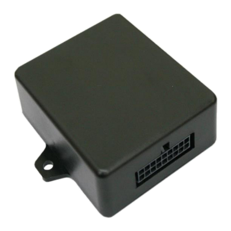
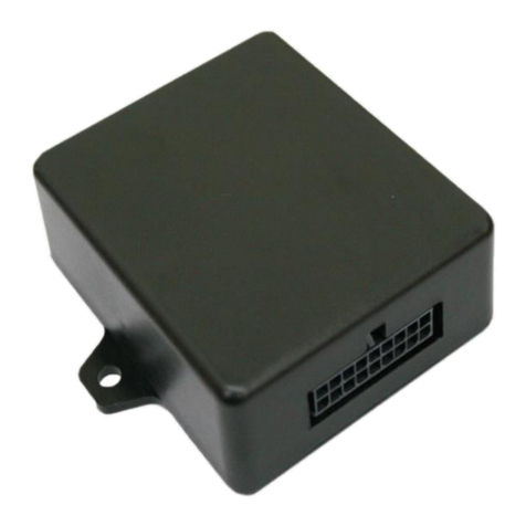
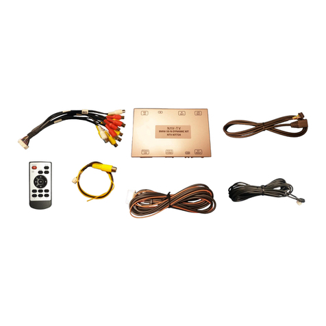
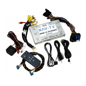
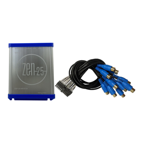
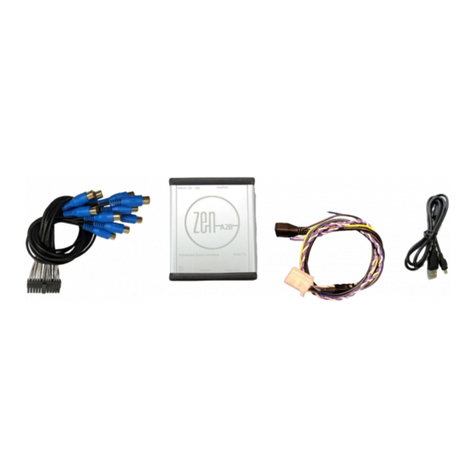
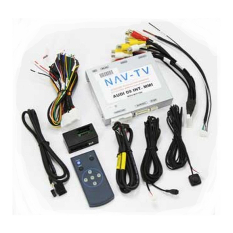
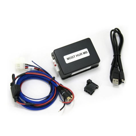
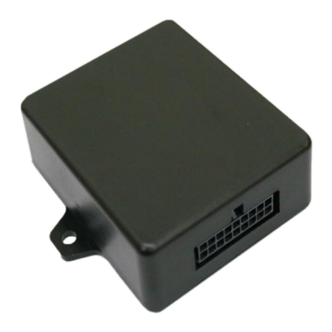
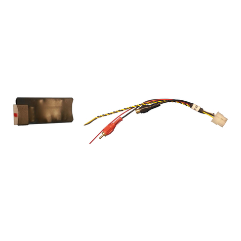
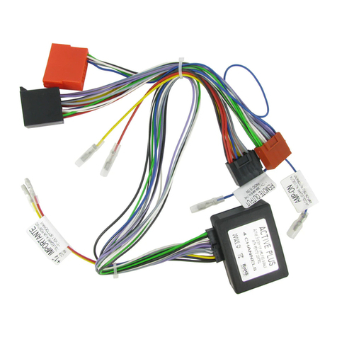
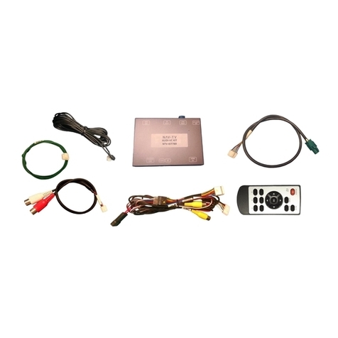
Video Interface Module wiring CAN Interface Module wiring
6 Pin Power Connector:
Pin (1) Constant +12volt (Yellow wire) prewired
Pin (2) Accessory +12volt (Red wire) prewired
Pin (3) Control2 (Gray wire) prewired
Pin (4) Ground (Black wire) prewired
Pin (5) Camera (Green wire) prewired
Pin (6) iDrive (White wire) prewired
Note: 6 Pin Power Connector plugs into output harness
from CAN interface module.
Note: When connecting the Molex power harness to the
video interface module, make sure that the locking tab on
the Molex connector is towards the top of the video
interface module.
6 Pin Connector – RGB In:
Pin (1) Red (Red wire)
Pin (2) Green (Green wire)
Pin (3) Blue (Blue wire)
Pin (4) Sync (White wire)
Pin (5) Ground (Black wire)
Pin (6) IR-NAVI (Orange wire)
Note: For connecting an external RGB Based Navigation
system to vehicle.
4 Pin Connector:
Pin (1) Constant +12volt in(Yellow wire)
Pin (2) Ground in(Black wire)
Pin (3) CAN Low (Orange/Gray wire), To Pin (6) factory
screen harness (yellow wire)
Pin (4) CAN High (Orange/Green wire), To Pin (5) factory
screen harness (black wire)
8 Pin Connector:
Pin (1) IR Out (White wire) positive output
Pin (2) Speed out (Dark Blue wire) positive output
Pin (3) Light out (Brown wire) positive output
Pin (4) Reverse out (Green wire) positive output (Backup
camera power)
Pin (5) Accessory +12volt out (Red wire) also accessory
power for the video interface module
Pin (6) iDrive out (Gray wire) positive output
Pin (7) Constant +12volt out (Yellow wire) also primary
power for the video interface module
Pin (8) Ground out (Black wire) also primary ground for the
video interface module
Note: The 8 Pin connector outputs are for powering and
activating accessories. Also has the 6 Pin Molex connector
that connects to the video interface module power
connection.
Note: Solder all connections. Do not use any crimp type connectors or terminals. CAN Bus signal degradation will
cause vehicle system problems if crimp type connectors or terminals are used.
DIP Switch Settings Menu Switch
1. NAVI Enable
2. AV1 Enable
3. AV2 Enable
4. Not used
5. Camera Enable
6. Not used
7. CH - - LPM (If On interface will restart in last mode
playing when vehicle was shut off).
8. 8.8/6.5 Screen selection (Off - 6.5, On – 8.8)
Note: Dip switches in the down position are On.
Press Menu Key:
1. Less than 1 Second, No action.
2. Longer than 1 Second, Input switch
3. Longer than 3 Seconds, Wide/Normal change
(8.8 wide panel only)
Note: For manual switching if desired
AV1 / AV2 Input Pinouts Connections
Pin (1) Video
Pin (2) Left Audio
Pin (3) Right Audio
Pin (4) Ground
Pin (5) Not Used (orange wire)
Pin (6) IR out (gray wire)
Connect the factory LVDS harness into the LVDS IN on the
video interface module, and then plug in the LVDS harness
into the LVDS OUT and into the factory LVDS connector on
the display.
The power connector on the video interface module plugs
into the output harness from the CAN interface module.
To power for the modules is supplied from the main power
harness to the CAN interface module.
Agreement: End user agrees to use this product in compliance with all State and Federal laws. NAV-TV Corp. would not be held liable for misuse of its product.
If you do not agree, please discontinue use immediately and return product to place of purchase.
