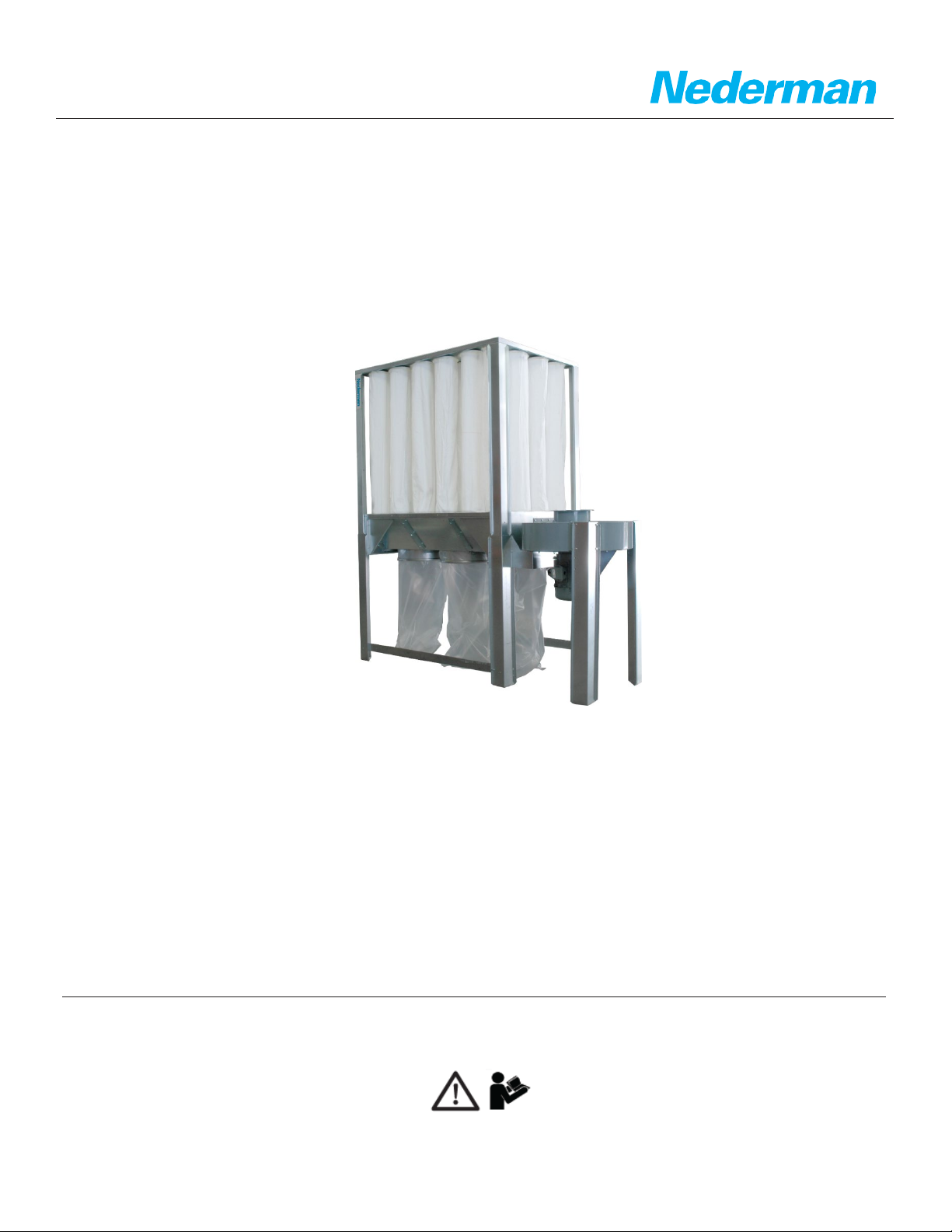
ELECTRICAL INSTALLATION, WIRING AND TROUBLESHOOTING
Nederman Customer Service & Technical Support techsupport.us@nedermen.com +1 (336) 821-0800
4
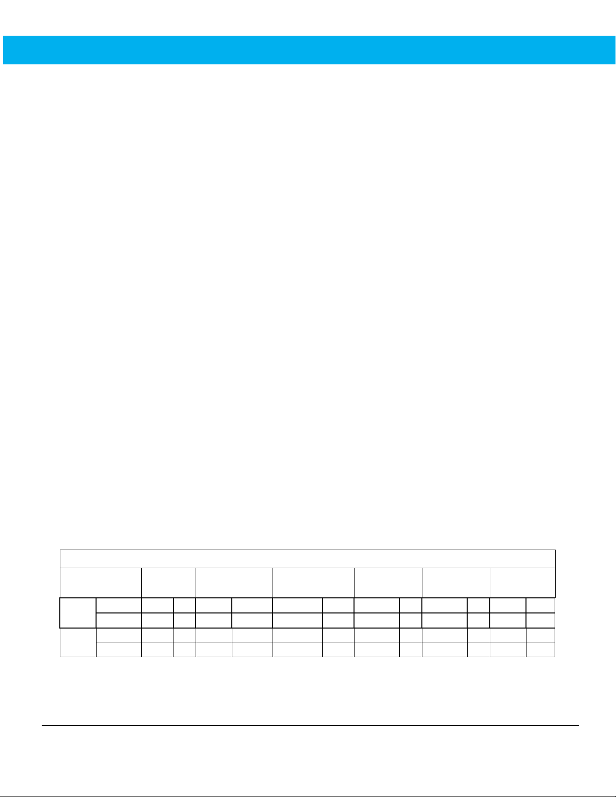
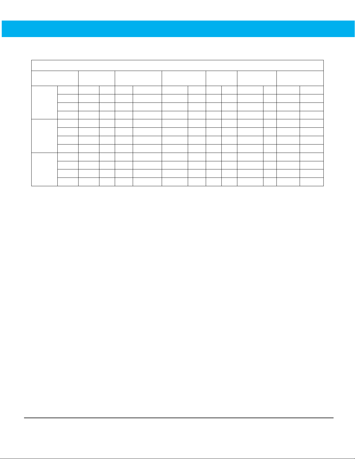
Section 2.0 – Circuit Sizing
1 Techtop motor nameplate full‐load amps (Used for setting overload only).
2 Minimum size based on 75ᵒC (167ᵒF) insulation and copper wire, such as RHW, THHW, THW, THWN, XHHW,
XHWN,USE, ZW. Verify with table 310.16. Conductor size may need to be increased based on wire type, length
and/or run.
3 Branch circuit protection to be sized at 250% of motor FLC for (Inverse Time) circuit breaker based on tables
430.52, 430.248, and 430.250. Based on 2020 NEC 70 Article 430 and best‐practice.
4 Branch circuit protection to be sized at 175% motor FLC for Dual Element (Time‐Delay) Fuse based on tables
430.52, 430.248, and 430.250. Based on 2020 NEC 70 Article 430 and best‐practice.
5 Branch circuit protection to be sized at 300% motor FLC for Nontime‐Delay fuse (Class CC fuses) on tables
430.52, 430.248, and 430.250. Based on 2020 NEC 70 Article 430 and best‐practice.
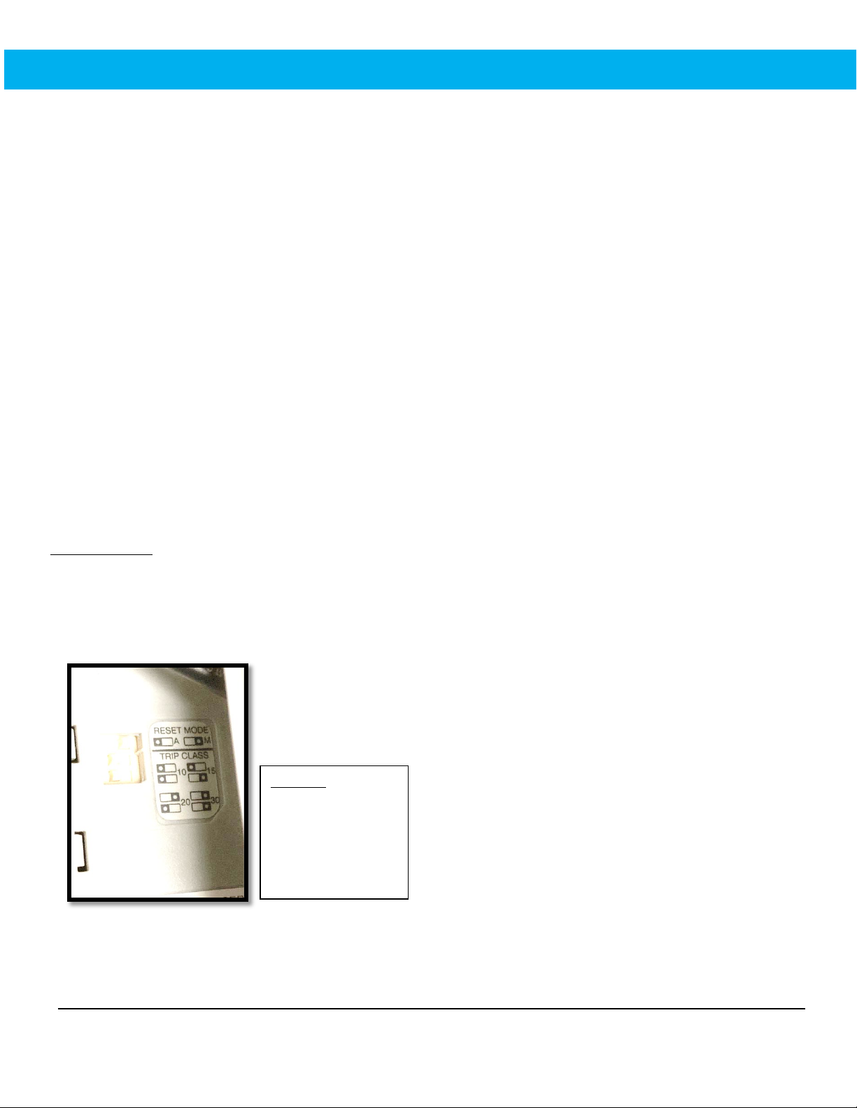
6 Recommended setting for overload on Nederman Push Button Starters based on motor nameplate multiplied by
service factor.
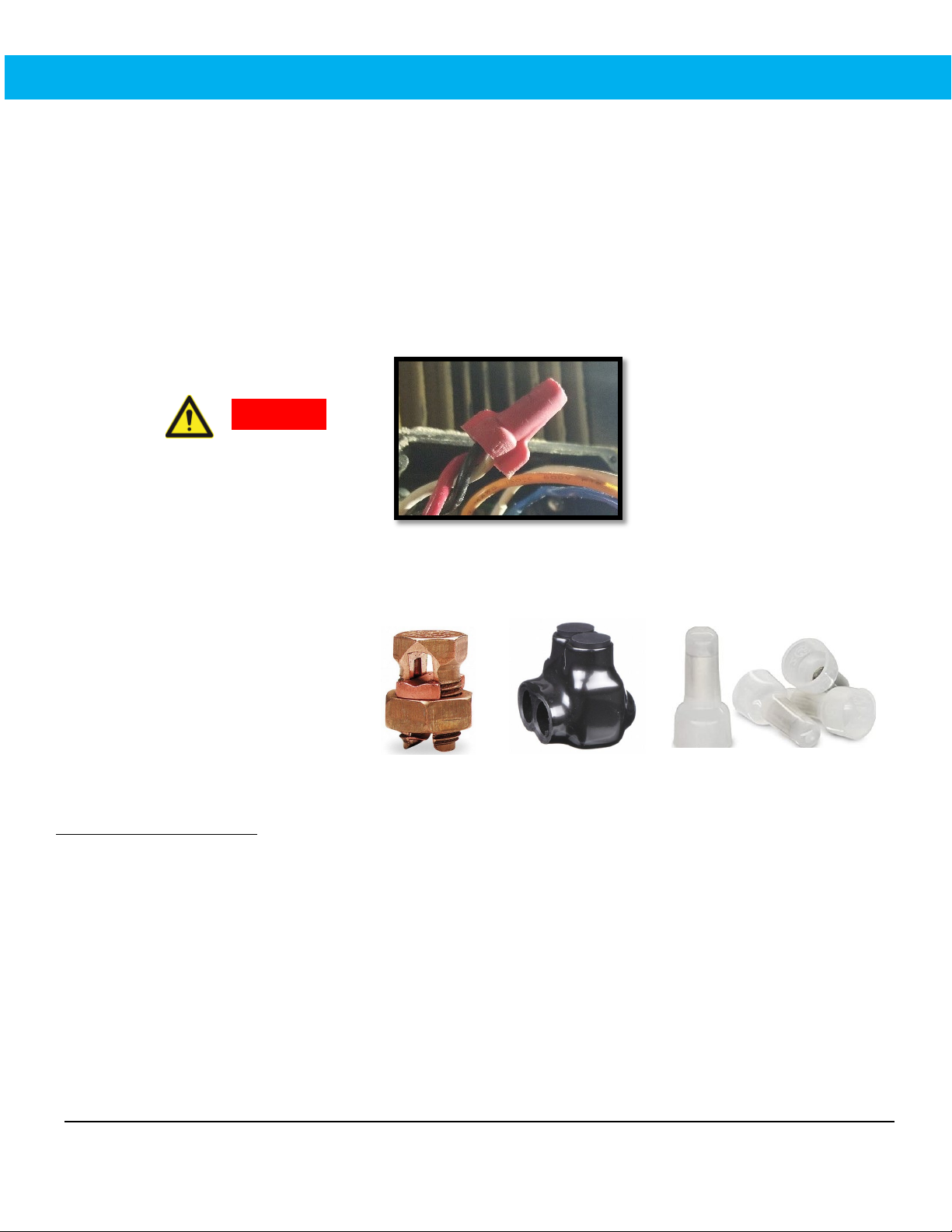
7 Wire‐nuts or soldering are
NOT
acceptable means to connect motor leads per NFPA 79, 13.5.9. Use appropriate
components to make motor connections such as split bolts, crimp‐connections and eye‐bolts.
8 It is the responsibility of the end‐user to follow State and Local Codes. This chart is provided as a helpful
resource only. Use of a qualified and licensed industrial electrician is required for proper installation.
TABLE 2 - 3-Phase S-Filter Circuit Sizing Table8
ServiceFactor 1.0 Motor FLA1Conductor Size2,7
Breaker Size3
Time‐Delay
Fuse4Non Time‐Delay5O/L Setting6
S‐500
460V 6.18 A 12 AWG 20 A 15 A 25 A 8 A
S‐750
208V 19.2 A 10 AWG 70 A 45 A 80 A 24 A
460V 8.6 A 12 AWG 30 A 20 A 35 A 11 A
575V 7.08 A 12 AWG 25 A 20 A 30 A 9 A
S‐1000
230V 23.9 A 8 AWG 70 A 50 A 90 A 30 A
575V 9.55 A 12 AWG 30 A 20 A 30 A 12 A