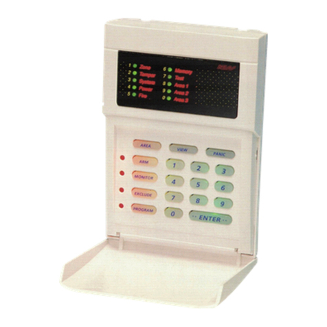
Ness ECO8x Assembly instructions

Revision 1.5
A$15.00
Ness ECO8x ALARM CONTROL PANEL
INSTALLATION & PROGRAMMING MANUAL
ECO8x

“Australia’s largest
designer and
manufacturer of
high quality security
products”
www.ness.com.au
Head Office:
Ness Security Products Pty Ltd
ABN 28 069 984 372
Ph +61 2 8825 9222 Fax +61 2 9674 2520
NSW
Ph 02 8825 9222 Fax 02 9674 2520
VIC
Ph 03 9875 6400 Fax 03 9875 6422
QLD
Ph 07 3399 4910 Fax 07 3217 9711
WA
Ph 08 9328 2511 Fax 08 9227 7073
SA
Ph 08 8152 0000 Fax 08 8152 0100

CONTENTS
Installation notes .......................................................................................4
Input and output descriptions...................................................................5
CONNECTION DIAGRAM / DEVICES WIRING.....................................6–7
Keypad ......................................................................................................8
OPERATION
Operation Summary .................................................................................9
HOW TO PROGRAM
Quick start Programming........................................................................10
How to enter Program Mode ..................................................................11
GENERAL OPTIONS
User Codes .......................................................................................12–13
Timers......................................................................................................14
Vibration Sensitivity.................................................................................15
Zone Assignment.........................................................................16–17,19
Area mapping..........................................................................................17
Definitions. Day Zones, Temp Day Zones, Home ..................................18
Zone To Output Mapping..................................................................20–21
Various Options.................................................................................22–23
Tamper/Keypad Panic Output Mapping .................................................24
System Operation Shortcuts...................................................................25
Home mode output mapping .................................................................26
Day mode output mapping.....................................................................26
Miscellaneous Options .....................................................................27–28
Aux1 Output options ...............................................................................29
Aux2 Output options ...............................................................................30
Misc. options ....................................................................................31–33
TELEPHONE NUMBERS ........................................................................34
Account Numbers ...................................................................................35
Alarm reporting options .....................................................................36-37
Test Call options......................................................................................38
Dialler format options.........................................................................39-44
RESET FACTORY DEFAULTS.................................................................45
SPECIAL INSTALLER FUNCTIONS
Send test report ....................................................................................46
Siren test / Panel reset /Display software version
RADIO OPTIONS ....................................................................................47
Signal strength test, Ness Radio Interface connection
RADIO DEVICE PROGRAMMING ..........................................................48
RADIO KEY PROGRAMMING .................................................................49
Real Time Clock options.........................................................................50
MONITORING OPERATION
Monitoring operation, Contact ID codes ................................................52
Audible Monitoring..................................................................................53
PROGRAMMING OPTIONS SUMMARY ...........................................54–55
Specifications and approvals..................................................................56

INSTALLATION
WARNING
Installation and maintenance shall be
performed by qualified service personnel
only.
CAUTION
Risk of explosion if battery is replaced by
an incorrect type. Dispose of used batteries
according to the instructions on the battery.
ADSL NOTICE
ADSL broadband data can interfere with the
operation of your alarm dialler.
It is recommended that a quality ADSL filter be
installed as per the filter manufacturer's guidelines
in all premises with an alarm dialler installed.
ESD WARNING
(Electrostatic Discharge).
Once properly installed, Ness control panels are
well protected from ESD. However, take note of
the following precautions during installation.
The human body can generate static electricity
when it is insulated from earth - for instance by
walking over carpet.
ESD occurs (and a small shock is sometimes felt)
if an earthed metal object is then touched.
The installer should be aware that if he generates
static electricity while installing the panel and then
discharges this static electricity into the internal
components on the main circuit board or the
keypad board, then ESD damage may occur.
The circuit board should not be unwrapped until it
is actually ready to be installed.
Methods to avoid electrostatic build-up.
1. Use a foot strap, a wrist strap, or a grounding
mat. The aim is to connect the body to earth
to discharge static before it builds up. The
connection is a high resistance for personnel
safety.
2. If the above is not available, then it is
advisable to wear clothing that will minimise
the build-up of static.
3. Handle circuit boards by the edges. Avoid
touching any components on the board as
the integrated circuits, in particular, are not
guaranteed by their manufacturers to be safe
from ESD.
4. To minimise the build-up of static, avoid
walking around as much as possible while
working on the installation.
5. Touch an earthed object to discharge any
static before working on the installation.
INSTALLATION PROCEDURES
The location of the main panel housing and all keypads should be
in an area that is within the protected area of the premises. A linen
closet or cupboard are good examples as these are generally located
in the centre of the premises.
Positioning of the movement detectors should be considered as the
incorrect position may cause unwanted alarms.
1. Remove the housing lid.
2. Remove the battery from the base.
3. Securely mount the rear panel housing to a secure location.
4. Run all cabling needed for the installation.
5. Before removing the circuit board from its protective wrapping.
6. Insert the PCB stand-offs in the panel and then plug the circuit
board onto the stand-offs.
7. Wire to the circuit board terminal blocks, as per the wiring
instructions shown in this installation manual.
8. Replace the battery.
9. Insert the panel tamper bracket as shown below.
10. Close the lid and program the panel as required.
Removable lid. Clip
this side first then
secure the lid with
screws provided.
Backup battery
holder. Fits
up to 12V 7Ah
battery.
Tamper switch on
lid protects lid and
box rear.
Provision for
slide-in accessory
boards.
Rear cable entry for
cavity walls. Top &
bottom knock-outs for
conduit entry.
Secure and easy
to fit standoffs for
the main board.
NESS EB04 ENHANCED HOUSING
4Ness eCO8xCONtrOl PaNel – INstallatION MaNual

OUTPUTS
MONITORED ZONES
The Ness ECO8x has multiple monitored inputs.
8 fully programmable zone inputs. (Monitored by end of line
resistor).
1 x 24 hour Box Tamper input. (Normally Closed input.
Resistor is not required).
ZONE INPUTS
Each zone input must be terminated with a 2K2 (2200 ohm)
resistor as supplied. All inputs must be sealed with an EOL
resistor.
For wiring details of Keypads, Keyswitches, Panic Buttons
and Warning devices, see the wiring diagrams in the wiring
section of this manual.
AC INPUT TERMINALS
These terminals are for the connection of AC power. The
Ness ECO8x requires an AC transformer rating of 1.4 Amps
@ 17 V AC minimum. (Ness Part No. 840-029 or POW215)
BATTERY
These terminals are for the connection of a sealed lead-acid
rechargeable 12 Volt battery. Charge current is limited to
350mA. The charge voltage is factory preset at 13.8V and
does not need changing. Note: A 12 Volt sealed lead acid
rechargeable battery must be connected for correct panel
operation. Observe correct polarity when connecting the
battery.
(Ness Part Number BAT210 12V 7Ah battery)
EARTH
For maximum protection against damage caused by
lightning strikes, connect a good earth to this terminal.
Alternatively use the Earth lead from the plug pack.
PROG/TAMP – Program Link & Internal Tamper Input
The PROG/TAMP link has two purposes:
1. To enter Installer Program Mode on initial power up.
Power-up with the PROG link OFF. The PROG link (or Box
Tamper lead) must be ON in operating mode.
2. Box Tamper. When used with the Internal Tamper Lead
(supplied), PROG/TAMP serves as the 24hr tamper input for
the panel’s internal tamper switch. This circuit should not be
wired external to the box.
Replace the PROG Link with the Box Tamper Lead. Connect
the Internal Tamper Lead spade terminals directly to the
terminals of the internal tamper switch (supplied). An end-of-
line resistor is NOT required on this input.
When PROG/TAMP is used for Internal Tamper, powering
up with the panel’s cover open will enter Installer Program
Mode.
INPUTS
12 VOLT OUTPUT
A regulated 13.8 VDC output is available to power detectors
and other equipment. This output is protected by an Automatic
Reset fuse.
A maximum load of 500mA may be connected.
SIREN
The on-board siren driver will drive a maximum of 3 x 8 ohm
horn speakers (Ness Part No. NOI110). The output will reset
at the end of siren time (P29E) or whenever the panel is reset,
whichever comes first.
This output is protected by an Automatic Reset fuse.
STR
A latched 12VDC output for connecting strobe lights.
This output will reset after 72 hours (3 days) or when the panel
is disarmed.
A maximum of 2 x 1 Watt Strobes (Ness Part No. NOI300) can
be connected to this output.
This output is protected by an Automatic Reset fuse.
RESET
A 12V DC output for connecting Ness sirens, piezo sirens
or relays, etc. This output will reset at the end of siren time
(P29E) or whenever the panel is reset, whichever comes first.
A maximum of 2 x 12V piezo screamers (Ness Part No. 100-
238, 100-004, 100-172) can be connected to this output.
This output is protected by an Automatic Reset fuse.
AUX1
The Aux 1 output is on the main terminal strip. Programmable
for Smoke Detector power, Area1 arm output or Radio Key
AUX button output (default), see program option P65E. Max.
current draw 200mA.
AUX2
The Aux2 output is a two pin header J3. Aux2 is an open
collector output (switches negative). Programmable for various
types of outputs, see program option P66E. Max. current draw
100mA.
OUTPUT FUSING. The 12V outputs, Siren, Reset and
Strobe outputs are protected by Automatic Reset elec-
tronic fuses. These outputs will automatically reset once
the overload is removed.
BACKUP BATTERY. A properly charged battery must
be installed to ensure the Siren, Strobe and Reset outputs
operate correctly.
SIREN LOAD. A maximum output of 2.0A continuous is
available from the SIREN and RESET outputs and 200mA
from the STR output.
Recommended maximum power load:
3 x Horn speakers (SIREN output)
2 x Strobe lights (STR output)
2 x Ness Internal Sirens (100-172) (RESET output)
Note: (This assumes no more than 500mA is being drawn from the
12V device outputs).
5
Ness eCO8xCONtrOl PaNel – INstallatION MaNual

ECO8x CONNECTION DIAGRAM
NOTICE
ADSL broadband can interfere with the operation of your alarm dialler.
It is recommended that a quality ADSL filter be installed as per the filter
manufacturer's guidelines. Use Ness ADSL Filters 100-006 or 100-009.
6Ness eCO8xCONtrOl PaNel – INstallatION MaNual

EXAMPLE 5 SIREN WIRING
EXTERNAL INTERNAL
Z8
Z8
C
C
100-238 Top Hat 12V Piezo Screamer
Flush Piezo Screamer
100-172 Ness 12V Internal Siren
100-004
RED
RED
BLACK
BLACK
N.O TAMPER SWITCH
(761-002) Colour: BLACK
N.C TAMPER SWITCH
(SWI920) Colour: WHITE
ALTERNATIVE TAMPER SWITCH WIRING
For N.C. Tamper Switches
STROBE LIGHT
(NOI300)
The terminal block should
be mounted inside the
siren cover.
HORN
SPEAKER
(NOI110)
NESS ECO8x
CONTROL
PANEL
NESS ECO8x
CONTROL
PANEL
NESS ECO8x
NESS ECO8x
CONTROL
PANEL
NESS ECO8x
CONTROL
PANEL
0V
ALARM
TAMPER
N.C.
N.C.
+12V
N.C.
N.C.
NESS QUANTUM DETECTOR
(all models)
REED SWITCH
(N.C. contacts))
PANIC BUTTON
(N.O. contacts))
Zone [1~8]
Zone [1~8]
Zone [1~8]
Zone [1~8]
0V
C
+12V
0V
CC
+12V
0V
CC
+12V
2K2
2K2
NESS QUANTUM DETECTORS 4 WIRE CONNECTION
0V
ALARM
TAMPER
N.C.
N.C.
+12V
N.C.
N.C.
NESS QUANTUM DETECTOR
(all models)
Any zone
programmed
as 24hr
0V
CC
C
+12V
2K2
2K2
EXAMPLE 2 NESS QUANTUM DETECTORS 6 WIRE CONNECTION
With Tamper
EXAMPLE 4
ANY N.C. DEVICE
ANY N.O. DEVICE
NC
NO
COM
EXAMPLE 1 EXAMPLE 3
2K2
2K2
2K2
ECO8x DEVICES WIRING
7
Ness eCO8xCONtrOl PaNel – INstallatION MaNual

KEYPAD
The Ness ECO8x keypad provides
important visual and audible indication
of the system status and is the main
interface for controlling the many
powerful features of the system.
NUMBER OF KEYPADS
Up to 3 keypads can be connected to
the ECO8x panel.
KEYPAD INSTALLATION
Connect the wires to the screw
terminals as per the wiring diagram
shown in this manual.
The keypad housing can be screwed
directly to the wall through the screw
holes on the front of the fascia. Cover
plugs for the mounting holes are
supplied. Left and right hand cover
plugs are different, (marked 'L' and 'H'
on the inside of the plug).
CABLE LENGTH
The maximum allowable cable length
is 100m (total cable length to all
keypads).
KEYPAD DISPLAY INDICATORS IN MEMORY MODE
KEYPAD LIGHT MEMORY EVENT
Zone lights 1–8 Zone alarm
(no lights) Panel Disarmed
ARMED Panel Armed (or Area 1 Armed)
ARM2 Area 2 Armed
MAINS Mains power failure
BATTERY Low Battery
TAMPER Tamper alarm
EXCLUDE Panic alarm
LINE Telephone line fail
RADIO, EXCLUDE Radio Key Panic alarm
RADIO, BATTERY, ZONE Radio Device battery low, (Device number is indicated by
zone lights)
RADIO, BATTERY, ARM Radio Key battery low, (Radio Key number is NOT
indicated)
RADIO, TAMPER, ZONE Radio Device tamper alarm (Device number is indicated by
zone lights)
KEYPAD DISPLAY INDICATORS IN OPERATING MODE
KEYPAD LIGHT OFF ON FLASHING
ZONE LIGHTS 1-8 Zone is sealed. Zone is
unsealed.
Zone is in alarm.
ARMED
Red Illuminated button
Panel is disarmed. Panel is armed
(or Area 1 is
armed if using
Areas).
HOME
Yellow Illuminated button
Home Mode is
disarmed.
Panel is armed
in Home Mode.
Day Mode enabled,
(see page 18).
MEMORY
Red Illuminated button
Normal. Memory mode
selected.
New alarm/s in
memory.
EXCLUDE
Red Illuminated button
Normal. Zone/s are
Excluded.
PROGRAM
Red Illuminated button
Normal. User Program
Mode.
Installer Program
Mode.
ARM2 (Yellow LED)
Area 2 is Disamed. Area 2 is
Armed.
BATTERY (Red LED)
Normal. The backup battery
is low.
MAINS (Red LED)
Normal. Mains power is off.
READY (Green LED)
Zone/s are unsealed.
or Power is off.
or Panel is armed.
or phone line fault.
Ready to arm
the panel.
TAMPER (Red LED)
Normal. The Internal Tamper
input is in alarm.
RADIO (Red LED)
Normal. Receiving a
radio signal. (If
radio fitted.)
A Radio Key or
other radio device
has low battery.
LINE (Red LED)
Normal Dialler is on
line.
Phone line fault
or failure to
communicate.
KEYPAD BEEPS
BEEPS MEANING
1 BEEP Any key press
3 BEEPS Valid Command
–– 1 LONG BEEP Error
–10–10 BEEPS Mains Power is off
or Panel Battery
is low
or A Radio Device
has sent a low
battery signal
or Telephone Line
Fail has been
detected
8Ness eCO8xCONtrOl PaNel – INstallatION MaNual

OPERATION SUMMARY
OPERATION by KEYPAD by RADIO KEY
to ARM
The panel must initially be disarmed. Press +
(If the Arming Shortcut is enabled, P62E 5E)
Press the ON button once.
or press + [user COde]+
or press [user COde]+
(If Code Only Arming has been enabled for that
user code. Extra Option 4E)
to DISARM
To disarm and/or reset alarms. Press [user COde]+ Press the
OFF button
once.*
to arm HOME MODE
Area1 must initially be disarmed.
Home Mode can be used if the panel
is fully disarmed or if only Area2 is
armed, see pages 18-19 for more
information.
Press +
(If the Home Mode Shortcut is enabled, P62E 3E)
Press either the
OFF button or the
ON button twice
within 4 seconds.
(P69E 5E must
be on).
or press + [user COde]+
PANIC alarm Press Fire & Medical keys together
(If KeyPad PaNIC is enabled, P64E 6E) Press and hold
the PANIC button
for at least 4 sec.
KEYPAD DURESS
Keypad Duress allows the user to send
a silent duress report while disarming, (if
the system is being monitored by a central
station).
Press [5, 6, 8 Or 9]+[user COde]+
Add one these digits in front of a user code when disarming.
This sequence will disarm the panel and send a Duress report by dialler to the central
station. (Report Keypad Duress must be enabled, P75E1E)
EXCLUDE ZONES
EXCLUDE + E can only be used when the
panel is disarmed.
EXCLUDE + CODE + E can be used
anytime.
Press +(If the Exclude Shortcut is enabled, P62E 2E)
then [ZONe NO.]+[ZONe NO.]+(Enter the zone number/s to be excluded.)
then press to exit Exclude mode
The Exclude light flashes constantly while zones are excluded. Excluded zones are
automatically Included next time the panel is disarmed.
* If a user code is assigned to a radio key and has Extra Option 4E enabled, (Code Only arming), then pressing OFF toggles the
panel arm/disarm state.
TEMPORARY DAY ZONE (TDZ) operation
While remaining in normal operating mode, the user can add and remove Temporary Day Zones and enable/disable day zone
operation.
The panel must initially be disarmed.
P64E 2E must be on to enable the
use of Temporary Day Zones.
See page 18 for more information on
Temporary Day Zones.
Press +To enter TDZ Selection Mode.
then press [ZONe NO.] +To select one or more zone to be Temporary Day Zones.
then press To save changes and exit TDZ Selection Mode.
Press +To enable/disable TDZ operation.
The HOME light flashes continuously when Day Mode is enabled
9
Ness eCO8xCONtrOl PaNel – INstallatION MaNual

QUICK START PROGRAMMING
Use one of these programming summaries for fast setup of your Ness ECO8x control
panel as a Local, Audible Monitored or Central Station Monitored system.
QUICK START 1 - LOCAL
SYSTEM
Quick Start 1 shows you how to
change User Code 1 (the Master
Code).
* Default Master Code is: 123
*Default Installer Code is: 000000
QUICK START 1
STEP KEYSTROKES DESCRIPTION COMMENT
1 P 1 2 3 E* Enters User Program Mode. Program light will turn on.
2P 1 1 E Selects the option for User Code 1. The existing code will be displayed
on the keypad one digit at a time.
3 _ _ _ _ E Enter your new PIN code followed
by E.
Keypad codes can be 3 to 6 digits
in length.
4 _ _ _ _ E Enter your new PIN code again. The new code will be displayed on
the keypad one digit at a time.
5 P E To exit program mode. Program light will turn off.
QUICK START 2
STEP KEYSTROKES DESCRIPTION COMMENT
1 P 1 2 3 E* Enters User Program Mode. Program light will turn on.
2 P 0 0 0 0 0 0 E* Enters Installer Program Mode. Program light will flash.
3P 1 1 E Selects the option for User Code 1. The existing code will be displayed
on the keypad one digit at a time.
4 _ _ _ _ E Enter your new PIN code followed
by E.
Keypad codes can be 3 to 6 digits
in length.
5 _ _ _ _ E Enter your new PIN code again. The new code will be displayed on
the keypad one digit at a time.
6 P 8 6 E 4 E Turns on option P86E 4E Enables Audible Monitoring.
7 P 7 0 E Selects the option for Telephone
Number 1.
The existing number will be displayed on
the keypad one digit at a time.
8 _ _ _ _ _ _ _ _ E Enter the telephone number
followed by E. (max. 30 digits)
The new number will be displayed on the
keypad one digit at a time.
9 P E To exit program mode. Program light will turn off.
QUICK START 2 -
AUDIBLE MONITORING
Quick Start 2 shows you how to
change User Code 1 (the Master
Code), enable Audible Monitoring
and program a telephone number.
This will enable the dialler to report
alarms to any telephone including
mobile phones.
QUICK START 3 -
CENTRAL STATION
MONITORING
Quick Start 3 shows you how to
change User Code 1 (the Master
Code), enable Central Station
Monitoring and program one
telephone number. This will enable
the dialler to report alarms to a
Central Station.
QUICK START 3
STEP KEYSTROKES DESCRIPTION COMMENT
1 P 1 2 3 E* Enters User Program Mode. Program light will turn on.
2 P 0 0 0 0 0 0 E* Enters Installer Program Mode. Program light will flash.
3P 1 1 E Selects the option for User Code 1. The existing code will be displayed
on the keypad one digit at a time.
4 _ _ _ _ E Enter your new PIN code followed
by E.
Keypad codes can be 3 to 6 digits
in length.
5 _ _ _ _ E Enter your new PIN code again. The new code will be displayed on
the keypad one digit at a time.
6 P 8 6 E 2 E Turns on option P86E 2E Enables Contact ID format.
7 P 7 0 E Selects the option for Telephone
Number 1.
The existing number will be displayed on
the keypad one digit at a time.
8 _ _ _ _ _ _ _ _ E Enter the telephone number
followed by E. (max. 30 digits)
The new number will be displayed on the
keypad one digit at a time.
8 P 7 2 E Selects the option for the Client
Account Number.
The existing number will be displayed on
the keypad one digit at a time.
10 _ _ _ _ E Enter the Account number
followed by E. (4 digit account number
supplied by your monitroing company.)
The new number will be displayed on the
keypad one digit at a time.
11 P E To exit program mode. Program light will turn off.
10 Ness eCO8xCONtrOl PaNel – INstallatION MaNual
PROGRAMMING

[INSTALLER CODE]
Factory default Installer Code: 000000
[MASTER CODE]
Factory default Master Code: 123
USER PROGRAM Mode
INSTALLER PROGRAM Mode
NORMAL OPERATING Mode
Power up with Program Link OFF
(Usually on first time installation)
PROGRAM LIGHT IS FLASHING
PROGRAM LIGHT IS ON
PROGRAM LIGHT IS OFF
PROGRAM MODE LEVELS
TABLE 4. FLOW CHART
INSTALLER PROGRAM MODE
Installer Program Mode allows
access to ALL program options.
Note: The panel will remain
in Installer Program Mode
indefinitely.
USER PROGRAM MODE
User Program Mode allows the
owner to program:
• All User Codes
• Entry Exit Times
• Follow Me Telephone number
Note:
The panel will automatically exit
User Program Mode to Operating
Mode if no keypad buttons are
pressed for 4 minutes.
HOW TO ENTER PROGRAM MODE
FROM POWER UP
1. Power-up with the PROG link OFF.
(The PROG link (or Box Tamper lead) must be ON in Operating Mode).
... OR
USING THE KEYPAD
The panel must be disarmed.
1. Press +[Master COde]+
This is User Program Mode (PROGRAM light is ON).
2. Press +[INstaller COde]+
This is Installer Program Mode (PROGRAM light is FLASHING).
HOW TO EXIT PROGRAM MODE
1. Press +
Exits directly to Operating Mode (PROGRAM light is OFF).
FACTORY DEFAULTS
Master Code: 123
Installer Code: 000000
11
Ness eCO8xCONtrOl PaNel – INstallatION MaNual
PROGRAMMING

PROGRAM MODE LEVEL
User, Installer, Remote by PC
FACTORY DEFAULT
User Code 1: 123
All other codes: [blank]
NOTES
1. To clear all codes (except the Installer
Code), enter P98E in Installer Program
mode. This also defaults user code 1 to
123. See Page 45.
2. Open/Close reports are identified by
user number when the control panel is
base station monitored.
RELATED OPTIONS
Installer Code. See Page 11, How To
Enter Program Mode.
Page 45, Programming The Installer
Code.
Installer Code default: 000000
RELATED OPTIONS
Programming Radio Codes, page 49
RADIO PROGRAMMING See pages 48-49.
USER CODES
The ECO8x control panel has 15 User Codes which are used to operate the panel by a
variety of methods – each User Code can be assigned to either a KEYPAD CODE or a
RADIO KEY.
KEYPAD (PIN) CODES
Up to 15 Keypad Codes can be used at up to 3 wired keypads for controlling all
panel functions including Arming/Disarming, Home Mode, Panic, memory
recall and much more.
• Keypad Codes can be 3 to 6 digits in length and can be individually
programmed and deleted.
• Keypad Codes can optionally be programmed to be "Arm Only" codes.
• User Code 1 is also the Master Code which is used to enter Client Program mode.
• All User Codes are Keypad Codes by default. User Codes can be programmed to be
Radio Codes as required.
NOTES
1. Keypad Codes beginning with 0 (zero) can be programmed but they will not operate
the panel. This is an alternative method for disabling user codes. The MEMORY E function
is recommended for deleting user codes.
2. All codes must be unique to each other. Codes are rejected if already used. Some codes
that are similar to existing codes may also be rejected.
PROGRAMMING KEYPAD CODES
Press P [11–25] E (The existing code is displayed one digit at a time).
Press [NEW CODE] E [NEW CODE AGAIN] E (The new code is displayed).
Example: To program the Master Code to be 1234.
Press P11E 1234E (1 beep) 1234E (3 beeps)
When re-programming an existing keypad code, the new code will overwrite the
old code.
DELETING KEYPAD CODES
To delete a User Code without programming a new code, press the MEMORY key in
place of the code.
Example: To delete User Code 2, press P12E MEMORY E
A keypad code only needs to be deleted if you're not replacing it with a new
code.
ARM ONLY CODES
'Arm Only' is an extra option for user codes. See next page for further information.
User Codes 2–15 can optionally be programmed as Arm Only Codes, which can Arm
but cannot Disarm the panel. (Used for cleaners, temporary staff, etc).
Example: To program User Code 2 to be 1234 and an Arm Only code.
Press P12E EXCLUDE E 3E EXCLUDE E 1234E 1234E
(EXCLUDE E enters Extra Options mode, 3E enables the Arm Only option, then
EXCLUDE E toggles back to normal user code program mode.)
When the code is viewed in program mode, the ARMED icon is briefly displayed before
the digits of the code.
To disable the Arm Only feature for a keypad code, simply enter the option for that
code, press EXCLUDE E to view Extra Options then press 3 E without re-entering a
new code. This retains the existing code and toggles off the Arm Only feature.
The Arm Only feature also applies to Radio Keys.
Arm Only codes can also arm the panel directly from Home Mode. (Normally,
user codes can arm the panel only if it is fully disarmed).
Arm Only codes can also arm Home Mode as normal.
Radio Keys programmed as an Arm Only can toggle the armed/disarmed state of
the panel using the OFF button on the radio key.
P11E – P25E
P01E – P08E
IMPORTANT NOTES
A User Code can be a Keypad Code,
Radio Code or Reader Code, but only
one type at any one time.
Any user codes not assigned to be
Radio Codes are automatically Keypad
Codes.
By factory default all user codes are
Keypad Codes.
When a user code is selected as a
Radio Code, its Keypad Code (if any) is
automatically deleted. The same applies
to Radio Codes - their codes are auto
deleted when the code is changed to any
other type.
User Code 1 is the Master Code and
is always a keypad code and cannot be
programmed to be a Radio Code.
12 Ness eCO8xCONtrOl PaNel – INstallatION MaNual
PROGRAMMING

PROGRAMMING USER CODES
ASSIGNING EXTRA OPTIONS
Each user code has several "extra options" which can be
assigned when programming the code or at any time later.
In NORMAL USER CODE PROGRAMMING mode
(Exclude light is off), you can do the following:
Program Keypad Codes (see page 12).
Program Radio Codes (see page 49).
View radio signal strength (see page 47).
USER CODE
OPTIONS TABLE
EXCLUDE+E toggles the EXTRA OPTIONS MODE.
The Exclude light indicates this mode is on/off.
(Installer Program mode only)
USER
CODE OPTION NO. KEYPAD PIN USER'S NAME
(For your record)
1E
AREA 1
CODE
2E
AREA 2
CODE
3E
ARM
ONLY
4E
"CODE ONLY"
ARM
5E
RADIO CODE
1 (Master) P11E 123 ON ON
2 P12E ON
3 P13E ON
4 P14E ON
5 P15E ON
6 P16E ON
7 P17E ON
8 P18E ON
9 P19E ON
10 P20E ON
11 P21E ON
12 P22E ON
13 P23E ON
14 P24E ON
15 P25E ON
In EXTRA OPTIONS mode (Exclude light is on), you can assign
several powerful functions to each user code.
To view and program the Extra Options:
1. Select a User Code (P201–P256E). The Exclude light is OFF.
2. Press EXCLUDE E. The Exclude light turns ON.
This gives access to programming Extra Options for codes:
1E AREA 1 CODES. Assign/remove user codes to Area 1. (By default all
user codes are assigned to Area 1.
2E AREA 2 CODES. Assign/remove user codes to Area 2.
User codes can be assigned to Area 1, Area 2, both areas or no areas.
An Area will not arm unless it has one or more zones assigned to it
(P45E, P46E).
If a code is not assigned to any Area/s, the code can be used for special
functions such as to trigger outputs.
3E ARM ONLY. User Codes 2–56 can be programmed to Arm but not
Disarm the panel. (See page 12).
4E "CODE ONLY" ARMING. Enables selected user codes to allow "code
only arming". Arming can then be done either with or without the use of
the arm key on the keypad.
In the case of radio codes the radio key OFF button will toggle the armed
state of the area assigned to the radio key.
If the User code is assigned to both AREA 1 and AREA 2. If AREA 1 is
already armed, then entering the code will disarm AREA 1 - but arm AREA 2.
If the intention is to either ARM or DISARM both areas using this code then
ARM + [code] must be used first to arm both areas. Once both are armed
they can be disarmed.
If in Home mode, then the action is to exit Home mode.
5E RADIO CODE. Enables selected user codes as Radio Codes for
operation by Ness Radio Key or Radio Keypad. (Page 49 - how to
program Radio Codes).
13
Ness eCO8xCONtrOl PaNel – INstallatION MaNual
PROGRAMMING

Option No. Description Default Note
P26E ENTRY DELAY TIME 20 seconds
P28E EXIT DELAY TIME 60 seconds
P29E SIREN RESET TIME 5 minutes
ENTRY DELAY TIME
The Entry Delay Time is the time given to disarm the panel after an Entry Delay zone is
triggered.
The Entry Delay Time setting is from 1 to 99 seconds in 1 second increments.
PROGRAMMING SEQUENCE:
P26E existing time is displayed one digit at a time
[ENTER NEW TIME] E new time is displayed one digit at a time
EXAMPLE: To program Entry Delay Time to be 30 seconds: P26E 30E
P26E
PROGRAM MODE LEVEL
User, Installer, Remote by PC.
FACTORY DEFAULT
20 (seconds)
NOTES
• Programmable from 1 – 99 seconds.
EXIT DELAY TIME
The Exit Delay Time is the time given to secure and depart the premises after the panel
is armed. All zones in the Area being armed (except 24hr zones) are inactive during the
Exit Delay time.
The Exit Delay Time setting is from 1 to 99 seconds in 1 second increments.
PROGRAMMING SEQUENCE:
P28E existing time is displayed one digit at a time
[ENTER NEW TIME] E new time is displayed one digit at a time
EXAMPLE: To program Exit Delay to be 85 seconds:
P28E 85E
P28E
PROGRAM MODE LEVEL
User, Installer, Remote by PC.
FACTORY DEFAULT
60 (seconds)
NOTES
• Programmable from 1 – 99 seconds
RELATED OPTIONS
P62E 8E Exit Time x10
SIREN RESET TIME
The Siren Reset Time sets the duration of the Siren and Reset outputs.
The Siren Reset Time setting is from 1 to 99 minutes in 1 minute increments.
PROGRAMMING SEQUENCE:
P29E existing time is displayed one digit at a time
[ENTER NEW TIME] E new time is displayed one digit at a time
EXAMPLE: To program Siren Time to be 4 minutes:
P29E 4E
P29E
PROGRAM MODE LEVEL
Installer, Remote by PC.
FACTORY DEFAULT
5 (minutes)
NOTES
• Programmable from 1 – 99 minutes.
• Siren times of longer than 5 minutes are
contrary to noise pollution regulations in
most areas.
14 Ness eCO8xCONtrOl PaNel – INstallatION MaNual
PROGRAMMING

P30E – P36E
PROGRAM MODE LEVEL
Installer, Remote by PC.
FACTORY DEFAULT
Normal sensitivity.
P30E, all zones = ON.
NOTES
• Sensitivity can be individually
programmed for each zone.
• Zones are allocated to one sensitivity
level at any one time. Turning a zone ON
in a sensitivity level, turns the zone OFF in
any other sensitivity level.
• To revert zone sensitivity back to
Normal, turn on the required zone/s at
P30E.
Ness NESSENSOR™Vibration Sensor
Part No. VIB100
In addition to zone sensitivity adjustment, the overall sensitivity of the Nesssensor can be
adjusted by rotating the body of the Nesssensor within its bracket.
ADJUSTING NESSENSORS
Nessensors are sensitive to high
frequencies and insensitive to low
frequencies. Therefore it is not
necessary to apply much force to
the protected structure, rather a very
rapid succession of blows.
The sensitivity has been correctly
adjusted when a single blow applied
with a soft object (e.g. by hand) does
not cause an alarm whereas a rapid
series of blows (using a metal object
such as a screwdriver blade) will
cause an alarm.
Sensitivity Level "Extreme"
(P31E) is provided as a guide to
the upper limit and should NOT
BE USED.
M
H
LL
RED
YELLOW
N/C Vibration
contacts
N/C Tamper
loop
BLUE
GREEN
36mm
51mm
20mm
16.5mm
350mm cable
2 x
at 27mm spacing
3mm holes
M
H
LL
M
H
LL
M
H
LL
M
H
LL
M
H
L
L
The Nessensor bracket
must always be mounted
horizontally and the arrow
must point up for any
required setting.
VIBRATION SENSITIVITY
Each zone has individually adjustable sensitivity for connection of Nessensor Vibration
Sensors. Zone sensitivity is adjusted by toggling zones ON in options P30E to P36E.
P30E is Normal Sensitivity, vibration analyser disabled. This is used for normal alarm
devices. Zone response time, 200ms.
P31–36E are the options for the 6 levels of vibration sensitivities. P31E is the most
sensitive setting.
PROGRAMMING SEQUENCE:
P [30–38] E zones are displayed [Zone No] E
EXAMPLE: To program zones 2 and 3 to be Medium sensitivity:
P34E 2E 3E the keypad display will show zone lights 2 & 3 on.
P37E – P38E
PROGRAM MODE LEVEL
Installer, Remote by PC.
FACTORY DEFAULT
all off
NOTES
• A Long Response Zone cannot be a
Normal Zone or Vibration zone at the same
time.
• To convert zone/s back to a Normal Zone,
turn on the required zone/s at P30E.
ZONES
Option No. Description 12345678
P30E NORMAL ON ON ON ON ON ON ON ON
VIBRATION OPTIONS
P31E Vibration EXTREME*
P32E Vibration HIGHEST
P33E Vibration HIGH
P34E Vibration MEDIUM
P35E Vibration LOWER
P36E Vibration LOWEST
P37E 1 second ZONES
P38E 3 second ZONES
* Extreme sensitivity (P31E) should not be used. It is provided as a guide only
LONG RESPONSE ZONES
Long Response Zones are normal alarm zones with a long reaction time. Individual
zones can be programmed to have either a 1 second response (P37E) or 3 second
response (P38E).
PROGRAMMING SEQUENCE:
P37E or P38E [Zone No]E toggles zones ON and OFF
15
Ness eCO8xCONtrOl PaNel – INstallatION MaNual
PROGRAMMING

ZONE DELAY TYPES
Only one option per zone can be selected.
For example, a zone cannot be instant and
delayed at the same.
ZONES
Option No. Description 12345678
P39E DOUBLE TRIGGER zones
P40E INSTANT zones ON ON ON ON ON ON
P41E ENTRY DELAY 1 zones ON
P42E HANDOVER zones ON
P44E LOCKOUT zones (Reset O/P) ON ON ON ON ON ON ON ON
P45E AREA 1 zones ON ON ON ON ON ON ON ON
P46E AREA 2 zones
P51E HOME zones
P52E 24HR zones
P53E DAY zones
DOUBLE TRIGGER ZONES
Zones programmed to Double Trigger will recognise an alarm condition if:
• The zone has been triggered twice within a 4 minute period.
• If any 2 zones (both programmed for double trigger), each trigger once.
• The zone is left unsealed for longer than 15 seconds.
PROGRAMMING SEQUENCE:
P39E [Zone No]E toggles the options ON and OFF
[Zone No] OFF: The zone is not a Double Trigger zone
[Zone No] ON: The zone is a Double Trigger zone
P39E
PROGRAM MODE LEVEL
Installer, Remote by PC.
FACTORY DEFAULT
All OFF.
NOTES
Double Trigger is useful for preventing
unwanted alarms from zones in harsh
environments such as sheds and
garages.
PROGRAMMING SHORTCUTS
Use 0E to turn all selections OFF.
Use MEMORY E to turn all selections ON.
INSTANT ZONES
Instant Zones operate only in the Armed state. When Armed at the expiry of exit time,
Instant Zones will activate assigned outputs immediately when triggered.
P40E [Zone No]E turns the options ON
[Zone No] ON: The zone is an Instant Zone
To deselect the option, select a different zone delay type.
P40E
PROGRAM MODE LEVEL
Installer, Remote by PC.
FACTORY DEFAULT
Zones 3–8 are Instant.
NOTES
When a zone is selected for this type, it is
automatically deselected from any other
delay type.
ENTRY DELAY1 ZONES
Entry Delay1 zones operate only in the Armed state. When Armed, at the expiry of exit
time these zones will activate the Entry Delay Timer1 (P26E) when they are triggered.
If the panel is not disarmed before the expiry of the Entry Delay Timer1, the alarm
outputs will be activated.
P41E [Zone No]E turns the options ON
[Zone No] ON: The zone is an Entry Delay1 zone
To deselect the option, select a different zone delay type.
P41E
PROGRAM MODE LEVEL
Installer, Remote by PC.
FACTORY DEFAULT
Zone 1.
NOTES
• The keypad sonalert will beep during
Entry Delay as a reminder to disarm the
panel. Entry beeps can be disabled by
program option P60E 1E.
• When a zone is selected for this type, it
is automatically deselected from any other
delay type.
16 Ness eCO8xCONtrOl PaNel – INstallatION MaNual
PROGRAMMING

AREA PARTITIONING
HANDOVER ZONES
Handover zones are delayed only if entry is made through an Entry Delay zone first.
If a Handover zone is triggered first, the zone behaves as an instant zone. Normally,
the “point of entry” zone should be Delay zone, with any other zones in the entry path
programmed as Handover zones.
PROGRAMMING SEQUENCE:
P42E [Zone No]E turns the options ON
P42E [Zone No]E ON: The zone is a Handover zone
To deselect the option, select a different zone delay type.
P42E
PROGRAM MODE LEVEL
Installer, Remote by PC.
FACTORY DEFAULT
2E ON.
NOTES
• When a zone is selected for this type, it
is automatically deselected from any other
delay type.
RESET LOCKOUT ZONES
All zones and tamper input can be programmed to Lockout, i.e. cause the RESET
OUTPUT to sound only once whilst the panel is armed.
The RESET OUTPUT is then locked out for that alarmed zone until entering a valid
code has reset the panel. If using area partitioning, disarming either partition resets the
zone lockout for both partitions.
PROGRAMMING SEQUENCE:
P44E [Zone No]E toggles the options ON and OFF
P44E [Zone No]E OFF: The zone is not a Lockout zone
P44E [Zone No]E ON: The zone is a Lockout zone
P44E
PROGRAM MODE LEVEL
Installer, Remote by PC.
FACTORY DEFAULT
All ON.
NOTES
• The SIREN output always locks out.
PROGRAMMING SHORTCUTS
Use 0E to turn all selections OFF.
Use MEMORY E to turn all selections ON.
RELATED OPTIONS
P60E 4E Tamper Reset Lockout.
P78E Multiple alarm reports.
ASSIGNING ZONES TO AREAS
Assign (or remove) zones that will operate in Area 1 and/or Area 2.
PROGRAMMING SEQUENCE:
P45E [Zone No]E toggles the options ON and OFF for Area1
[Zone No] OFF: The zone is not in Area1
[Zone No] ON: The zone is in Area1
P46E [Zone No]E toggles the options ON and OFF for Area2
[Zone No] OFF: The zone is not in Area2
[Zone No] ON: The zone is in Area2
EXAMPLE:
To program zones 1–4 for Area 1 and zones 1, 5–8 for Area 2.
P45E use the [Zone No] E sequence to turn ON only zones 1–4.
P46E use the [Zone No] E sequence to turn ON zones 1, 5–8.
In this example, we have assigned zone 1 to both areas, so it becomes a Common
Zone.
P45E, P46E
PROGRAM MODE LEVEL
Installer, Remote by PC.
FACTORY DEFAULT
All zones assigned to Area 1.
No zones assigned to Area 2.
NOTES
• For options P45E and P46E, [Zone No] E
toggles the selection ON and OFF.
• Zones assigned to BOTH areas
become Common zones.
• If no Area operation is required, assign
all zones to Area 1. (This is the factory
default).
ASSIGNING ZONES TO AREAS ZONES
Option No. Description 1 2 3 4 5 6 7 8
P45E AREA 1 ZONES ON ON ON ON ON ON ON ON
P46E AREA 2 ZONES
17
Ness eCO8xCONtrOl PaNel – INstallatION MaNual
PROGRAMMING

AREA PARTITIONING
DEFINITION
Area Partitioning allows the control panel
zones to be split into two partitions; Area1
and Area2. The panel then effectively oper-
ates as two separate systems sharing only
the siren outputs and dialler.
COMMON AREA ZONES
Zones assigned to both Areas are armed
only when Area1 and Area2 are both armed.
This allows the Common Area zone/s to be
shared by both Areas.
For example, Office A and Office B operate
as separate areas but the entrance foyer
used by both offices is assigned to both
areas meaning it will automatically arm when
both Areas have armed. The Common Area
then automatically disarms when either
Area1 or Area2 disarms.
USER CODE ASSIGNMENT
A User Code assigned to an Area can arm
and disarm only that Area. User Codes as-
signed to both Areas will operate both Areas
simultaneously.
OPERATION
Arming and disarming is carried out as
normal from a single keypad or separate
keypads installed in both areas or by Radio
Key.
Area operation only applies to zones when
they are in the armed state. This means that
Day zones and 24hr zones are independent
of area operations.
The Temporary Day Zone feature allows
easy and flexible Day Zone selection and
operation.
While remaining in normal operating mode,
the user can add and remove Temporary
Day Zones and enable/disable day zone
operation using simple key strokes.
TO ENABLE TEMPORARY DAY ZONES
To enable Temporary Day Zone selection
and operation, the Brief Day Alarm feature
(installer option P64E 2E) must be ON. If
P64E 2E is OFF, the Temporary Day Zone
feature will be unavailable but Permanent
Day Zones will still operate and will sound
the programmed output while the zone is
unsealed.
P64E 2E is OFF by default.
USER COMMANDS (In normal Operat-
ing Mode).
+Selection Mode. Enter P
followed by E when in operating mode
to enter Temporary Day Zone selection
mode.
[Zone No.]+ Zone Selection. To select
or deselect zones to be Temporary Day
Zones. The selected zones are indicated by
the corresponding zone number.
Permanent Day Zones, (set by installer
option P53E), are not displayed in selection
mode. Permanent Day Zones can be
selected as Temporary Day Zones but this
has no effect as those zones are already
day zones.
Saves changes and returns to normal
operating mode.
+ Enables and Disables Day Mode.
This enables/disables both Temporary and
Permanent Day Zones.
INDICATION
The HOME light flashes continuously when
Temporary Day Mode is enabled.
OUTPUTS
When Day Mode is enabled, any unsealed
day zone will sound the programmed
output for 2 seconds. When Day Mode is
disabled, an unsealed day zone will simply
be indicated on the keypad as an unsealed
zone.
RELATED OPTIONS
P64E 2E, Brief Day Alarm. Turn this option
on to enable Temporary Day Zones. Factory
default = OFF.
P63E 5E, Day Mode to Reset output.
P63E 6E, Day Mode to Strobe output.
If P64E 2E is ON, then this option sends day
alarms to the AUX 2 output.
P63E 7E, Day Mode to Sonalert.
P63E 8E, Day Mode to Siren output.
P53E, Permanent Day Zone selection.
Temporary Day Zone selections will be
lost if the panel is powered down or reset,
but are not affected by arming/disarming or
entering program mode.
TEMPORARY DAY ZONES
HOME MODE
Home Mode allows selected zones to be armed
whilst the system is disarmed. For example, this
is often used to arm door and windows sensors
overnight, while allowing free movement within
the house.
• Home Mode will not work if Area 1 is armed.
• Zones which are to be armed in Home Mode
are selected using option P51E.
• Home Mode can be armed by:
Keypad: HOME+[code]+E or HOME+E
Radio Key: See option P69E 5E
• Audible outputs in Home Mode (set by
options P63E 1E-4E) are independent of
audible outputs in fully armed mode.
• If dialler reporting is enabled, Home Mode
alarms will be reported as normal providing
that:
a/ The zone/s are selected to report alarms
by option P74E.
b/ Option P64E 1E is off. (Brief Home Mode
Alarm).
• Home zones can be Instant, Delayed or
Handover depending on attributes set by
options P40E–P42E.
AREA PARTITIONING
& HOME MODE
The panel can be armed in HOME Mode
if Area2 is already armed on these condi-
tions:
1. Area 1 must be OFF.
2. Area 2 must be armed first, and then
Home armed – not the reverse.
3. Zones assigned to both Home mode
(P51E) and to Area 2 (P46E) will act
as Home zones when both Area 2 and
Home are armed.
4. Zones must be assigned to P51E to
allow Home arm.
Note: Home arming when AREA 2 is
armed cannot be done by Radio Key
(double OFF button) or by keyswitch.
Note: Home Mode is not available when
Area 1 is armed.
18 Ness eCO8xCONtrOl PaNel – INstallatION MaNual
PROGRAMMING

DAY ZONES
Day Zones operate when the panel is fully disarmed, i.e. when Area 1, Area 2 and
Home Mode are all off. When alarmed, these zones will activate their assigned outputs
instantly.
The outputs mapped to the Day Zone will turn on while the zone is unsealed. Turn
P64E 2E on, to limit Day Zone alarms to 2 seconds.
The Temporary Day Zones feature allows day mode to be easily enabled/disabled and
day zones added/removed by the user from any keypad.
PROGRAMMING SEQUENCE:
P53E [Zone No]E toggles the options ON and OFF
[Zone No] OFF: The zone is not a Day zone
[Zone No] ON: The zone is a Day zone
P53E
PROGRAM MODE LEVEL
Installer, Remote by PC
FACTORY DEFAULT
all OFF.
RELATED OPTIONS
P63E 5E-8E Day zone output mapping.
P64E 2E Brief Day Mode alarm.
IDEAS FOR DAY ZONE USE
• Instant alert for a delivery door.
• Doorway alert for a shop.
• Pool gate opened warning.
24hr ZONES
24hr Zones operate at all times regardless of the mode of panel operation, i.e. Armed,
Disarmed or Home Mode. When alarmed, these zones will activate assigned outputs
immediately. To reset those alarms a valid user code must be entered.
Selecting a zone as 24hr will override any other zone type setting such as Instant,
Delayed or Handover. 24hr zones are independent of Area operation. All other zone
types must be assigned to at least one Area to become active.
PROGRAMMING SEQUENCE:
P52E [Zone No]E toggles the options ON and OFF
[Zone No] OFF: The zone is not a 24hr zone
[Zone No] ON: The zone is a 24hr zone
P52E
PROGRAM MODE LEVEL
Installer, Remote by PC.
FACTORY DEFAULT
All OFF.
NOTES
• When a zone is selected as 24hr it is
automatically removed from both Areas.
• When a 24hr zone is assigned to an
Area (P45E or P46E) it is no longer a 24hr
zone.
HOME MODE ZONES
Home Mode zones allow you to Arm selected zones while others are ignored. Typically
used for perimeter zones such as windows and doors while you are at home.
For example: upstairs zones are Disarmed while downstairs zones are Armed in Home
mode.
PROGRAMMING SEQUENCE:
P51E [Zone No]E toggles the options ON and OFF
P51E [Zone No]E OFF: The zone is not a Home zone
P51E [Zone No]E ON: The zone is a Home zone
P51E
PROGRAM MODE LEVEL
Installer, Remote by PC.
FACTORY DEFAULT
all OFF.
NOTES
Home zones can be Instant, Delayed or
Handover depending on attributes set by
options P40E–P42E.
RELATED OPTIONS
P63E 1E-4E Home Mode output mapping.
P64E 1E Brief Home Mode alarm.
P69E 3E Quiet Home Mode siren.
P69E 5E Home Mode by Radio Key ON/
OFF buttons.
P69E 7E Home Mode chirps.
P69E 8E Home Mode arm by Radio Key
AUX button.
NOTE: Zones selected to Report Zone Alarms (P74E) will by default report alarms in
Home Mode, (if the dialler is enabled).
The Brief Home Alarm option P64E 1E, when enabled, prevents Home Mode alarms
from reporting.
See page 18 for information on TEMPORARY DAY ZONES.
See page 18 for Home Mode operation.
19
Ness eCO8xCONtrOl PaNel – INstallatION MaNual
PROGRAMMING

ZONE TO OUTPUT MAPPING
When a zone alarms, it can turn on any or all of these outputs: Sonalert, Strobe,
Siren, Reset, AUX2.
The programming is selected with options P54E – P59E. Simply set the zone
number to the output to select it. The zone LED will indicate if the zone is se-
lected.
The Tamper Input and the Keypad Panic can be mapped to the Reset, Strobe,
Sonalert and Siren by using option P61E.
MAPPING ZONES TO OUTPUTS ZONES
Option No. Description 1 2 3 4 5 6 7 8
P54E RESET Zones ON ON ON ON ON ON ON ON
P55E STROBE Zones ON ON ON ON ON ON ON ON
P56E SONALERT Zones ON ON ON ON ON ON ON ON
P57E SIREN Zones ON ON ON ON ON ON ON ON
P59E AUX2 Zones
Zone To Output Mapping
applies to zones when the panel is
in the Armed or 24hr state.
For HOME MODE and DAY mode
Output Mapping – see Option
P63E 1E–8E, page 26.
P54E
PROGRAM MODE LEVEL
Installer, Remote by PC.
FACTORY DEFAULT
All ON.
PROGRAMMING SHORTCUTS
Use 0E to turn all selections OFF.
Use MEMORY E to turn all selections ON.
RESET OUTPUT ZONES
Selects the zones to trigger the Reset output.
PROGRAMMING SEQUENCE:
P54E [Zone No]E toggles the options ON and OFF
[Zone No] OFF: The zone will not trigger the Reset output
[Zone No] ON: The zone will trigger the Reset output
P55E
PROGRAM MODE LEVEL
Installer, Remote by PC.
FACTORY DEFAULT
all ON.
PROGRAMMING SHORTCUTS
Use 0E to turn all selections OFF.
Use MEMORY E to turn all selections ON.
STROBE OUTPUT ZONES
Selects the zones to trigger the Strobe output.
PROGRAMMING SEQUENCE:
P55E [Zone No]E toggles the options ON and OFF
[Zone No] OFF: The zone will not trigger the Strobe output
[Zone No] ON: The zone will trigger the Strobe output
P56E
PROGRAM MODE LEVEL
Installer, Remote by PC.
FACTORY DEFAULT
All ON.
PROGRAMMING SHORTCUTS
Use 0E to turn all selections OFF.
Use MEMORY E to turn all selections ON.
KEYPAD SONALERT ZONES
Selects the zones which will sound the Keypad Sonalert (beeper).
PROGRAMMING SEQUENCE:
P56E [Zone No]E toggles the options ON and OFF
[Zone No] OFF: The zone will not trigger the Keypad Sonalert
[Zone No] ON: The zone will trigger the Keypad Sonalert
20 Ness eCO8xCONtrOl PaNel – INstallatION MaNual
PROGRAMMING
Other manuals for ECO8x
1
Table of contents
Other Ness Control Panel manuals
Ness
Ness D-8 User manual
Ness
Ness D16 User manual
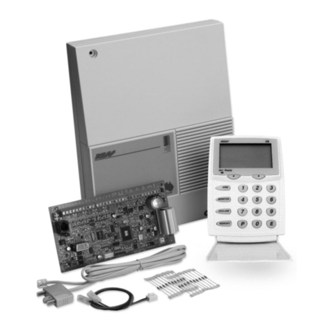
Ness
Ness D16 Assembly instructions

Ness
Ness D-8 Assembly instructions
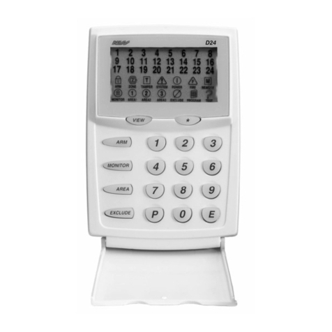
Ness
Ness D24 User manual
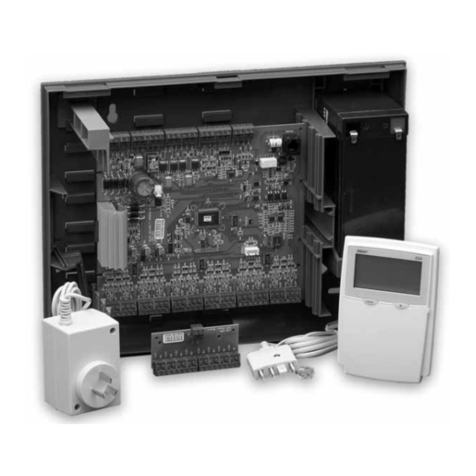
Ness
Ness D24 Assembly instructions
Ness
Ness L-8 User manual
Ness
Ness D16 Assembly instructions
Ness
Ness M1 Cross Platform Control User manual
Ness
Ness D8xD User guide
Popular Control Panel manuals by other brands
Siemens
Siemens FIREFINDER-XLS Installation, operation and maintenance manual

Tangent Wave
Tangent Wave CP300 user manual
Proteco
Proteco Q45 new instruction manual

Viessmann
Viessmann Vitotronic 200 GW1 operating instructions

American Standard
American Standard NEXIA ACONT624AS42DA user guide

Nordelettronica
Nordelettronica NE274-TVDL instruction manual

