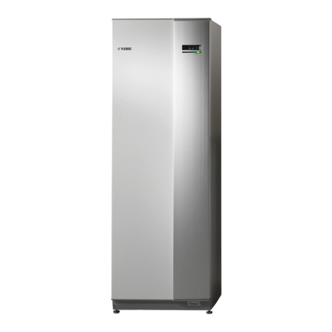
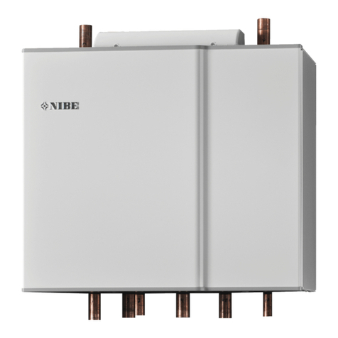
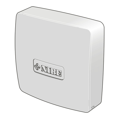
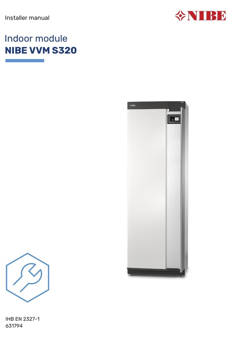
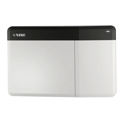
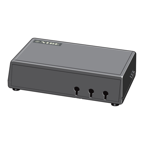
Nibe AXC 40 User guide

Installer manual
LEK
AXC 40
Accessories
IHB EN 1722-8
031444


Table of Contents
41 Important information
52 General
5Contents
5Component location unit box (AA25)
63 Common electrical connection
6Connecting communication
6Connecting the supply
74 Shunt controlled additional heat
7General
7Pipe connections
8Outline diagram
12Electrical connection
13Program settings
14Electrical circuit diagram
155 Step controlled additional heat
15General
15Pipe connections
16Outline diagram
20Electrical connection
21Program settings
22Electrical circuit diagram
236 Hot water circulation
23General
23Outline diagram
26Electrical connection
26Program settings
27Electrical circuit diagram
287 Groundwater pump
28General
28Outline diagram
30Electrical connection
31Program settings
32Electrical circuit diagram
3Table of Contents |AXC 40

NOTE
This symbol indicates danger to person or ma-
chine .
Caution
This symbol indicates important information
about what you should observe when maintain-
ing your installation.
TIP
This symbol indicates tips on how to facilitate
using the product.
AXC 40Chapter 1 | Important information4
1 Important information

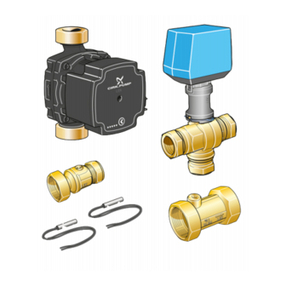
This accessory is used to enable connection and control
of (a AXC 40 is required for each of the following access-
ory functions that is used):
■Shunt controlled additional heat
■Step controlled additional heat
■Pump for hot water circulation
■Groundwater pump
Contents
Cable ties4 x
Heating pipe paste2 x
Insulation tape1 x
Unit box with accessory card1 x
Aluminium tape2 x
Temperature sensor2 x
Component location unit box
(AA25)
LEK
AA5-X4
AA5-S2
AA5-X2 AA5-X9 X1
FA1
AA5-F1AA5
Electrical components
Miniature circuit breaker, 10 AFA1
Terminal block, power supplyX1
Accessory cardAA5
Terminal block, sensors and external block-
ing
AA5-X2
Terminal block, communicationAA5-X4
Terminal block, circulation pump, mixing
valve and auxiliary relay
AA5-X9
DIP switchAA5-S2
Fine wire fuse, T4AH250VAA5-F1
Designations in component locations according to
standard IEC 81346.
5Chapter 2 | GeneralAXC 40
2 General

NOTE
All electrical connections must be carried out
by an authorised electrician.
Electrical installation and wiring must be carried
out in accordance with the stipulations in force.
The main product must be disconnected from
the power supply when installing AXC 40.
Electrical circuit diagrams are at the end of the chapter
for each connection option.
Connecting communication
This accessory contains an accessory board (AA5) that
must be connected directly to the compatible product
on the input board (terminal block AA3-X4).
If several accessories are to be connected or are already
installed, the following instructions must be followed.
The first accessory board must be connected directly to
the terminal block in the compatible product and the
following boards must be connected in series with the
previous board.
Use cable type LiYY, EKKX or similar.
1
2
3
4
5
6
7
8
AA5-X4
15
A
B
GND
A
B
GND
A
B
GND
A
B
GND
A
B
GND
14
13
AA3-X4
1
2
3
4
5
6
7
8
AA5-X4
1
2
3
4
5
6
7
8
15
14
13
1
2
3
4
5
6
7
8
Compatible product
Accessory card 1
Accessory card 2
ON
12345678
-X9
-X2
24 20212223 1516171819 1011121314 56789 1
1
N
L
PE
PE
1
2
3
4
5
6
7
8
2
3
4
5
6
7
8
9
234
-X8
-X4
-X10
-X1
ON
12345678
-X9
-X2
24 20212223 1516171819 1011121314 56789 1
1
N
L
PE
PE
1
2
3
4
5
6
7
8
2
3
4
5
6
7
8
9
234
-X8
-X4
-X10
-X1
AA5-X4
AA5-X4
AA3-X4
F1245/F1255
VVM 225/310/320/325/500
AA3-X4
F1145/F1155
Connecting the supply
Connect the power supply to terminal block X1 as illus-
trated.
3
2
1N
230V 50Hz
L
PE
AXC40 External
X1
AXC 40Chapter 3 | Common electrical connection6
3 Common electrical connection

General
This function enables an external additional heater, e.g.
an oil boiler, gas boiler or district heating exchanger to
aid with heating.
The heat pump controls a shunt valve (QN11) and a cir-
culation pump (GP10) via AXC 40. If the heat pump
cannot manage to maintain the correct supply temper-
ature, the additional heat starts. When the boiler tem-
perature has increased to about 55 °C, the heat pump
sends a signal to the shunt to open from the additional
heat. The shunt is governed so the true supply temperat-
ure corresponds with the control system’s theoretical
calculated set point value. When the heating require-
ment drops sufficiently, so that the additional heat is no
longer required, the shunt closes completely. Factory-set
minimum run time for the boiler is 12 hours (can be ad-
justed in menu 5.3.2).
Prioritised additional heat refers to heating from an ex-
ternal, non-controlled heat source which, if available, is
prioritised to be used before the heat pump. An example
of prioritised additional heat would be a wood fired
boiler or back boiler.
Compatible products
■F1145
■F1155
■F1245
■F1255
■VVM 225
■VVM 310
■VVM 320
■VVM 325
■VVM 500
Pipe connections
The external circulation pump (GP10) is positioned ac-
cording to the outline diagram.
Shunt valve
The shunt valve (QN11) must be placed on the supply
line to the climate system after the heat pump according
to the outline diagram.
AB
B
A
■Connect the supply line from the heat
pump to the external heat source via
the T-pipe to port B on the shunt
valve (closes on reduce signal).
■Connect the supply line to the climate
system from the shunt valve to the common port AB
(always open)
■Connect the supply line from the external additional
heat to the shunt valve to port A (opens on increase
signal).
Temperature sensor
■Install the boiler sensor (BT52) in a suitable location in
the external additional heat.
■External supply temperature sensor (BT25, connected
in the heat pump/indoor module) must be installed
on the supply line to the radiators, after the shunt valve
(QN11).
LEK
LEK
E
Install the temperature sensors using cable ties, together
with the heat conducting paste and aluminium tape.
Then insulate with the enclosed insulation tape.
NOTE
Sensor and communication cables must not be
placed near power cables.
7Chapter 4 | Shunt controlled additional heatAXC 40
4 Shunt controlled additional heat

Outline diagram
Explanation
Heat pump systemEB100
Temperature sensor, outdoorBT1
Temperature sensor, hot water chargingBT6
Temperature sensor, heating medium flow,
external
BT25
Expansion vessel, heating medium sideCM1
Heat pumpEB100
Safety valve, heating medium sideFL2
Circulation pump, externalGP10
Particle filterHQ1
Shut-off valve, heating medium sideQM31 -
QM32
External additional heatEM1
Unit box with accessory card (AXC 40)AA25
Temperature sensor, boilerBT52
Expansion vessel, closedCM5
Oil/gas boilerEM1
Safety valve, heating medium sideFL10
Auxiliary relay, external additional heatKA1
Mixing valve, additionQN11
Miscel-
laneous
Level vessel, collector sideCM2
Accumulator tank with hot water coilCP10
Collector, brine sideEP12
Safety valve, brineFL3
Filler valveQM12
Shut off valve, brine returnQM34
Shut-off valveQM42
Non-return valveRM1
Connection, filling brineXL15
Designations according to standard IEC 81346 - 1 and
81346 - 2.
Outline diagram F1145, F1155 with AXC 40 and shunt-controlled additional heat
-QM31
-QM32
-FL3
-QM42
-QM12
-CM2
-HQ1
-FL2
-CM1
-QM34
-XL15
-EB100-BT1
-EB100
-BT6
-EB100
-CP10
-QN11
-EM1 -BT52
-CM5
-KA1
-FL10
-EB100-BT25 -EM1-GP10
-AA25
-RM1
-EM1
-EP12
AXC 40Chapter 4 | Shunt controlled additional heat8

Outline diagram F1245, F1255 with AXC 40 and shunt-controlled additional heat
-FL3
-QM42
-QM12
-CM2
-QM34
-XL15
-EB100-BT1
-QM31
-QM32
-HQ1
-EB100
-FL2
-CM1
-EP12
-QN11
-EM1 -BT52
-CM5
-KA1
-FL10
-EB100-BT25 -EM1-GP10
-RM1
-AA25
-EM1
9Chapter 4 | Shunt controlled additional heatAXC 40

Outline diagram VVM 225 with AXC 40 and
shunt-controlled additional heat
-EB15
P
-XL4 -XL3
-QN11
-EM1 -BT52
-CM5
-KA1
-EM1
-FL10
-EB15 -BT25
-AA25
-XL1-XL2
-RM1
-EM1
-GP10
Outline diagram VVM 310 with AXC 40 and
shunt-controlled additional heat
For connection of an external energy source solely to
the heating system, suitable when the energy source has
a large volume, such as a wood boiler with an accumu-
lator tank. This connection uses the accessory AXC 40.
With the following example, the prioritised additional
heat function can be used.
-FL2
-CM1
-EB15 -XL2 -XL1
-QN11 -BT25
-AA25
-CP2
-EM1
-GP15
-BT52
-EM1
Outline diagram VVM 320 with AXC 40 and
shunt-controlled additional heat
-EB15
-QN11
-EM1 -BT52
-CM1
-KA1
-EM1
-FL2
-EB15 -BT25
-AA25
-XL1
-XL2
AXC 40Chapter 4 | Shunt controlled additional heat10

Outline diagram VVM 325 with AXC 40 and
shunt-controlled additional heat
-EB15
-XL1-XL2 -XL4-XL3
-QN11
-EM1 -BT52
-CM3
-KA1
-EM1
-FL2
-EB15 -BT25
-AA25
Outline diagram VVM 500 with AXC 40 and
shunt-controlled additional heat
-EB15-FL2
-EB15
-CM1
-EB15 -XL2 -XL1
-XL3
-XL4
-QN11
-EM1 -BT52
-CM3
-KA1
-EM1
-FL2
-EB15 -BT25
-AA25
11Chapter 4 | Shunt controlled additional heatAXC 40

Electrical connection
NOTE
All electrical connections must be carried out
by an authorised electrician.
Electrical installation and wiring must be carried
out in accordance with the stipulations in force.
The main product must be disconnected from
the power supply when installing AXC 40.
Overview accessory board (AA5)
ON
12345678
-X9
-X2
24 20212223 1516171819 1011121314 56789 1
1
N
L
PE
PE
1
2
3
4
5
6
7
8
2
3
4
5
6
7
8
9
234
-X8
-X4
-X10
-X1
AA5-X2 AA5-X9AA5-S2
Connection of sensors and external blocking
Use cable type LiYY, EKKX or similar.
Boiler sensor (BT52)
Connect the boiler sensor to AA5-X2:23-24.
External blocking (optional)
A contact (NO) can be connected to AA5-X2:21-22 to
block the additional heat. When the contact closes, the
additional heat is blocked.
24 20212223
BT52
AXC40
External
External blocking
AA5-X2
External supply temperature sensor (BT25)
Connect the supply temperature sensor to AA3-X6:5-6
on the input board in the heat pump.
F1145, F1155
1 2 3456 7 8 9
BT25
BT25
AA3-X6
AA3-X6
F1245, F1255, VVM 225, VVM 310, VVM 320, VVM 325,
VVM 500
AA3-X6
1
2
3
4
5
6
7
8
9
BT25
BT25
AA3-X6
Caution
The relay outputs on the accessory board can
have a max load of 2A (230V) in total.
Connection of the circulation pump (GP10)
Connect the circulation pump (GP10) to AA5-X9:8
(230V), AA5-X9:7 (N) and X1:3 (PE)
1
2
3
4
5
6
7
8
9
L
N
PE
3
2
1
AXC40 External
GP10
AA5-X9 X1
AXC 40Chapter 4 | Shunt controlled additional heat12

Connection of the shunt valve motor (QN11)
Connect the shunt motor (QN11) to AA5-X9:6 (230V,
open), AA5-X9:5 (N) and AA5-X9:4 (230V, close).
1
2
3
4
5
6
7
8
9
AXC40 External
QN11
N
SH +
Close
Open
AA5-X9
SH -
Connection of the auxiliary relay for
additional heating
Connect the auxiliary relay for switching the additional
heat on and off to AA5-X9:2 (230V) and AA5-X9:3 (N).
1
2
3
4
L
N
A1 A2
External auxiliary relay
Additional
Heating
AXC40 External
Additional
heat
AA5-X9
External auxiliary relay
DIP switch
The DIP switch (S2) on the accessory card (AA5) must be
set as follows.
ON
1 2 3 4 5 6 7 8
Program settings
Program setting of AXC 40 can be performed via the
start guide or directly in the menu system.
Start guide
The start guide appears upon first start-up after heat
pump installation, but is also found in menu 5.7.
Menu system
If you do not make all settings via the start guide or need
to change any of the settings, this can be done in the
menu system.
Menu 5.2 - system settings
Activating/deactivating of accessories.
Select: "shunt controlled add. heat".
Menu 5.3.2 - shunt controlled add. heat
Here you can perform the following settings:
■Select when the addition is to start.
■Minimum running time.
■Minimum boiler temperature at which the shunt can
start control.
■Misc. shunt settings.
Caution
"start addition" in the menus 5.3.2 (external)
and 4.9.3 (internal) are factory set at 400GM. If
both additional heat possibilities are used and
you wish one to start before the other the start
difference must be changed in one of the
menus.
Menu 5.6 - forced control
Forced control of the different components in heat pump
EM1-AA5-K1: Activating the relay for extra heating
EM1-AA5-K2: Signal (close) to mixing valve (QN11).
EM1-AA5-K3: Signal (open) to mixing valve (QN11).
EM1-AA5-K4: Activating the circulation pump (GP10).
Caution
Also see the Installer manual for the heat
pump/indoor module.
13Chapter 4 | Shunt controlled additional heatAXC 40

Electrical circuit diagram
0.000
MJN 2017-02-02
Production ASN 2012-03-29
WIRING DIAGRAM SHUNT CONTROLL
KRETSSCHEMA SHUNTSTYRD
051055 6
AXC 40Chapter 4 | Shunt controlled additional heat14

General
With AXC 40 a further three potential-free relays are
used for additional heat control, which then gives max
3 linear or 7 binary steps.
Compatible products
■F1145
■F1155
■F1245
■F1255
■VVM 225
■VVM 320
■VVM 325
Pipe connections
The extra circulation pump (GP10) is positioned accord-
ing to the outline diagram.
Temperature sensor
■External supply temperature sensor (BT25, connected
in the heat pump/indoor module) must be installed
on the supply line to the radiators, after the additional
heat.
LEK
LEK
E
Install the temperature sensors with cable ties with the
heat conducting paste and aluminium tape. Then insu-
late with supplied insulation tape.
NOTE
Sensor and communication cables must not be
placed near power cables.
15Chapter 5 | Step controlled additional heatAXC 40
5 Step controlled additional heat
Outline diagram
Explanation
External additional heatEB1
Unit box with accessory card (AXC 40)AA25
Expansion vessel, closedCM5
External electrical additional heatEB1
Safety valve, heating medium sideFL10
Shut-off valve, heating medium sideQM40 -
QM41
Trim valveRN11
Heat pump systemEB100
Temperature sensor, outdoorBT1
Temperature sensor, hot water chargingBT6
Temperature sensor, heating medium flow,
external
BT25
Expansion vessel, heating medium sideCM1
Heat pumpEB100
Safety valve, heating medium sideFL2
Circulation pump, externalGP10
Particle filterHQ1
Shut-off valve, heating medium sideQM31 -
QM32
Miscel-
laneous
Level vessel, collector sideCM2
Accumulator tank with hot water coilCP10
Collector, brine sideEP12
Safety valve, brineFL3
Filler valveQM12
Shut off valve, brine returnQM34
Shut-off valveQM42
Non-return valveRM5
Connection, filling brineXL15
Designations according to standard IEC 81346-1 and
81346-2.
Outline diagram F1145, F1155 with AXC 40 and step-controlled additional heat
-QM31
-QM32
-FL3
-QM42
-QM12
-CM2
-HQ1
-FL2
-CM1
-QM34
-XL15
-EB100-BT1
-EB100
-BT6
-EB100
-CP10
-CM5
-FL10
-QM40
-QM41
-EB1
-EB100-BT25
-RM5
-AA25
-EB1
-GP10
-RN11
-EB1
-EP12
AXC 40Chapter 5 | Step controlled additional heat16

Outline diagram F1245, F1255 with AXC 40 and step-controlled additional heat
-FL3
-QM42
-QM12
-CM2
-QM34
-XL15
-EB100-BT1
-QM31
-QM32
-HQ1
-EB100
-FL2
-CM1
-EP12
-CM5
-FL10
-QM40
-QM41 -RN11
-EB1
-EB100-BT25
-RM5
-EB1
-GP10
-AA25
-EB1
17Chapter 5 | Step controlled additional heatAXC 40

Outline diagram VVM 225 with AXC 40 and
step-controlled additional heat
P
-BT3
-BT7
-BT63
-BT2
-BT6
-XL1
-XL2
-EB1
-GP10
-XL4 -XL3
-EB15
-BT25
-CM5
-FL10
-QM40
-QM41 -RN11
-EB1
-AA5
-EB1
-XL7 -RM5
-EB15
Outline diagram VVM 320 with AXC 40 and
step-controlled additional heat
-EB15 -BT25
-EB15
-CM5
-FL10
-QM40
-QM41 -RN11
-EB1
-AA25
-EB1
-XL7
-XL2
AXC 40Chapter 5 | Step controlled additional heat18

Outline diagram VVM 325 with AXC 40 and
step-controlled additional heat
-EB15
-XL1-XL2 -XL4-XL3
-EB15 -BT25
-CM5
-FL10
-QM40
-QM41 -RN11
-EB1
-AA5
-EB1
-XL7
19Chapter 5 | Step controlled additional heatAXC 40

Electrical connection
NOTE
All electrical connections must be carried out
by an authorised electrician.
Electrical installation and wiring must be carried
out in accordance with the stipulations in force.
The main product must be disconnected from
the power supply when installing AXC 40.
Overview accessory board (AA5)
ON
12345678
-X9
-X2
24 20212223 1516171819 1011121314 56789 1
1
N
L
PE
PE
1
2
3
4
5
6
7
8
2
3
4
5
6
7
8
9
234
-X8
-X4
-X10
-X1
AA5-X2 AA5-X9AA5-S2
Connection of sensors and external blocking
Use cable type LiYY, EKKX or similar.
External blocking (optional)
A contact (NO) can be connected to AA5-X2:23-24 to
block the additional heat. When the contact closes, the
additional heat is blocked.
24 20212223
AXC40
External
External blocking
AA5-X2
External supply temperature sensor (BT25)
Connect the supply temperature sensor to AA3-X6:5-6
on the input board in the heat pump.
F1145, F1155
1 2 3456 7 8 9
BT25
BT25
AA3-X6
AA3-X6
F1245, F1255, VVM 225, VVM 320, VVM 325
AA3-X6
1
2
3
4
5
6
7
8
9
BT25
BT25
AA3-X6
Caution
The relay outputs on the accessory board can
have a max load of 2A (230V) in total.
Connection of the circulation pump (GP10)
Connect the circulation pump (GP10) to AA5-X9:8
(230V), AA5-X9:7 (N) and X1:3 (PE)
1
2
3
4
5
6
7
8
9
L
N
PE
3
2
1
AXC40 External
GP10
AA5-X9 X1
AXC 40Chapter 5 | Step controlled additional heat20
Other manuals for AXC 40
4
Table of contents
Other Nibe Control Unit manuals
Popular Control Unit manuals by other brands

Siemens
Siemens FT2018-U1 installation instructions

esera automation
esera automation 11211 user guide

Rockwell Automation
Rockwell Automation Allen-Bradley 1794-IRT8 user manual

DIEBOLD NIXDORF
DIEBOLD NIXDORF DN Series Operator's manual

Vimar
Vimar by-me Eikon Evo 21509 manual

Mitsubishi Electric
Mitsubishi Electric NZ2MF2S1-32D user manual

Rockwell Automation
Rockwell Automation Allen-Bradley ControlLogix DeviceNet... user manual

Robur
Robur Roburbox100 Installation and use manual

MD
MD mXion KBM user manual

Gantner
Gantner GAT NET.Controller 7000 Series manual

Siemens
Siemens SINUMERIK 840Di Diagnostic manual

Rauch
Rauch QUANTRON-A AXIS-M 20 Q instruction manual