Njoy Ranger 60KR User manual

Ranger 60KR User Manual
Manual de ulizare
UP33ROP160KRAAZ01B
Before using this product, carefully read all product documentaon and retain it for future reference.
233.24.23.1

2
Safety and EMC instrucons
1
Thank you for purchasing our products!
Please read this manual before using the product.
nJoy is a brand of power and backup protecon products that
create soluons for mulple levels of environment complexity,
residenal to industrial.
This UPS will protect your electronic equipment from physical
damage and will provide emergency baery backup power to
prevent data loss in the event of power problems.
All safety instrucons in this document must be read, understood and
followed.
1.1 Transportaon and Storage
Please transport the UPS system only in the original packaging to
protect against shock and damage.
The UPS must be stored in the room where the temperature is well
regulated. Ambient temperature should not exceed 40°C.
1.2 Preparaon
Condensaon may form if the UPS system is moved immediately from
cold to warm environment. The UPS system must be absolutely dry before
being installed. Please allow at least two hours for the UPS system to
acclimate the environment.

3
English
Română
Do not install the UPS system near water or in moist environments.
Do not install the UPS system where it would be exposed to direct
sunlight or nearby heat source.
Do not block venlaon holes on the UPS housing.
1.3 Installaon
Do not connect appliances or devices which would overload the UPS
(e.g. big motor-type equipment) to the UPS output terminal.
Place cables in such a way that no one can step on or trip over them.
Do not block air vents on the housing of the UPS. Ensure proper unit
spacing of venlaon.
UPS came equipped with grounding terminal, in the nal installaon
phase, connect grounding/earthing wire to the external UPS baery
cabinets or appropriate grounding terminals.
The UPS can be installed only by qualied maintenance personnel.
An appropriate disconnect device such as short-circuit backup
protecon should be incorporated during installaon.
An integral emergency shuto switch which prevents addional load
from the UPS in any mode of operaon should be implemented during the
installaon.
Secure the grounding/earthing wire before connecng to any live wire
terminal.
Installaon and Wiring must be in accordance with the local electrical
laws and regulaons.

4
1.4 Connecon Warnings
There is no standard backfeed protecon inside of the UPS. However,
there are relays on the Input to cut o line voltage and while the neutral is
sll connect to UPS.
This UPS should be connected with TN grounding/earthing system.
The power input for this unit must be three-phase rated in accordance
with the equipment nameplate. It also must be suitably grounded.
Use of this equipment in medical instrument of any life-sustaining
equipment where failure of this equipment can reasonably be expected to
cause the failure of the life-sustaining equipment or to signicantly aect
its safety or eecveness is not recommended. Do not use this equipment
in the presence of a ammable mixture with air, oxygen or nitrous oxide.
Connect grounding terminal of UPS to a grounding electrode conductor.
In accordance with safety standard EN-IEC 62040-1, installaon
has to be provided with a «Backfeed Protecon» system, as for example
a contactor, which will prevent the appearance of voltage or dangerous
energy in the input mains during a mains fault (respect the wiring diagram
of «Backfeed Protecon» depending if the equipment is with signal or three
phase input).
HIGH LEAKAGE CURRENT! EARTH CONNECTION ESSENTIAL
BEFORE CONNECTING SUPPLY.
WARNING
UPS
Main
Input
Input Rly
Input relay diagram Input relay diagram for
dual-input model
L1
L2
L3
L1
L2
L3
L1
L2
L3
N
UPS
Main
Input
Bypass
Input
Input Rly
Input Rly
N
N

5
English
Română
1.5 Operaon
Do not disconnect the grounding/earthing conductor cable on the UPS
or the building wiring terminals under any circumstance.
The UPS system features its own, internal current source (baeries).
The UPS output sockets or output terminal blocks may be electrically live
even if the UPS system is not connected to the building mains/live wires.
(only for standard models)
In order to fully disconnect the UPS system, rst press the “OFF” buon
and then disconnect the mains/live wires.
Ensure that no liquid or other foreign objects can enter into the UPS
system.
The UPS can be operated by any individuals with no previous
experience.
There can be no derivaon in the line that goes from the «Backfeed
Protecon» to the UPS, as the standard safety would be infringed.
Warning labels should be placed on all primary power switches installed
in places away from the unit to alert the electrical maintenance personnel
of the presence of a UPS in the circuit. The label will bear the following or
an equivalent text:
Before working on this circuit!
- Isolate Uninterruptible Power Supply (UPS).
- Then check for Hazardous Voltage between all terminals
including the protected earth.
Risk of Voltage Backfeed!
WARNING

6
2.1 Unpacking and Inspecon
Unpack the package and check the package contents. The shipping
package should contain:
● One UPS
● One user manual
● One monitoring soware CD
● One RS-232 cable (opon)
● One USB cable
● One parallel cable (only available for parallel model)
● One shared current cable (only available for parallel model)
These series came with a VAC system: 400V. Please refer to the following
table.
We also oer oponal parallel funcon for this model upon request. The
UPS with parallel funcon is called the “Parallel model”. We have detail
installaon and operaon procedure of the Parallel Model in the following
chapter.
2Installaon and Operaon
VAC System Model Type
400V Ranger 60KR Long-run
model
NOTE!
Before the installaon, please inspect the unit. Be sure that there is no physical
damage to the unit. Do not turn on the unit and nofy the carrier and dealer
immediately if there is any damage or missing parts and accessories. Please
keep the original packaging for future use. It is recommended to keep each
equipment and baery set in their original packaging because they have been
designed to provide maximum protecon during transportaon and storage.

7
English
Română
2.2 Wiring Terminal View
1. RS-232 communicaon port
2. USB communicaon port
3. Emergency power o funcon connector (EPO connector)
4. Share current port (only available for parallel model)
5. Parallel port (only available for parallel model)
6. Intelligent slot
7. External baery connector/terminal
8. External maintenance bypass switch signal port (EMBS)
9. Grounding terminal
10. Dry contact communicaon port (oponal)
11. Line input terminal
12. Bypass input terminal
13. Output terminal
Ranger 60KR Rear panel
2.3 Single UPS Installaon
Installaon and wiring must be carried out in accordance with the local
electric laws and regulaons by trained professionals.
1) Make sure that the mains wire and breakers of the building are rated for
the capacity of the UPS to prevent electric shock or risk of re.

8
NOTE 1: The cable for Ranger 60KR should be able to withstand over
120A current. It is recommended to use AWG 4 or thicker wire for Phase
and AWG 1 or thicker wire for Neutral for safety and eciency.
NOTE 2: The selecons for color of wires should be followed by the local
electrical laws and regulaons.
5) Remove the terminal block cover at the rear panel of UPS. Then connect
2) Switch o the mains switch in the building before installaon.
3) Turn o all the connected devices before connecng to the UPS.
4) Prepare wires based on the following table:
Model Wiring spec (AWG)
Input(Ph) Output(Ph) Neutral Baery Ground
Ranger 60KR 4 4 1 1 4
the wires according to the following terminal block diagrams: (Connect
the grounding/earthing wire rst when making other wire connecons.
Remove the grounding/earthing wire last when connecng the UPS!)
Terminal block wiring diagram for Ranger 60KR
NOTE!
Do not use the wall receptacle as the input power source for the UPS, as its
rated current is less than the UPS’s maximum input current. The receptacle
may be damaged and destroyed.

9
English
Română
Battery wires connection schematic
PBAT
NBAT
TO UPS BAT+
TO UPS BAT N
NOTE 1: Make sure that the wires are connected securely with the
terminals.
NOTE 2: Please install the output breaker between the output terminal
and the load, and the breaker should have leakage current protecve
funcon if necessary.
6) Put the terminal block cover back at the rear panel of the UPS.
TO UPS BAT-
● Make sure a DC breaker or other protecve device between UPS and
the external baery pack is installed for added safety. If not, please
install it carefully. Switch o the baery breaker before installaon.
NOTE: Set the baery pack breaker in “OFF” posion and then install
the baery pack.
● Pay special aenon to the rated baery voltage marked on the rear
panel. If you want to change the numbers of the baery in a chain,
make sure you modify the UPS seng accordingly. Connecon with
wrong baery voltage may cause irreversible damage of the UPS.
● Pay special aenon to the polarity marking on external baery
terminal block. Connecon with wrong baery voltage may cause
irreversible damage of the UPS.
WARNING

10
2.4 UPS Installaon for Parallel System
If the UPS is only for single operaon, you may skip this secon.
1) Install and wired the UPS according to the secon 2-3.
2) Connect the output wires of each UPS to an output breaker.
3) Connect all output breakers to a major breaker. This major output
breaker will then connect directly to the loads.
4) Either common baery packs or independent baery packs for each
UPS are allowed.
5) Refer to the following wiring diagram:
Wiring diagram of parallel system for Ranger 60KR
● Make sure the protecve grounding/earthing wiring is adequate.
The current spec, color, posion, connecon and conductance
reliability of the wire should be veried.
● Make sure the ulity input & output wiring is rated correctly. The
current spec, color, posion, connecon 8 and conductance reliability
of the wire should be veried. Make sure the L/N side is correct, not
reverse or short-circuited.

11
English
Română
2.5 Soware Installaon
For opmal computer system protecon, install UPS monitoring soware
to congure UPS shutdown operaon.
Operaons
3
Buon Funcon
ON/Enter Buon
Turn on the UPS: Press and hold the buon
more than 0.5s to turn on the UPS.
Enter Key: Press this buon to conrm the
selecon in the seng menu.
OFF/ESC Buon
Turn o the UPS: Press and hold the buon
more than 0.5s to turn o the UPS.
Esc key: Press this buon to return to last
item in the seng menu.
Test/Up Buon
Baery test: Press and hold the buon more
than 0.5s to test the baery while in AC mode
and CVCF* mode.
UP key: Press this buon to display next
selecon in the seng menu.
Mute/Down Buon
Mute the alarm: Press and hold the buon
more than 0.5s to mute the buzzer. Please
refer to secon 3-4-9 for details.
Down key: Press this buon to display
previous selecon in the seng menu.
Test/Up +
Mute/Down Buon
Press and hold the two buons
simultaneous more than 1s to enter/escape the
seng menu.
3.1 Buon Operaon
* CVCF means Constant Voltage and Constant Frequency.

12
3.2 LED Indicators and LCD Panel
LED Indicators:
There are 4 LEDs on front panel to show the UPS working status:
Note: “●” means LED is lighng, and “○” means LED is faded.
Mode LED Bypass Line Baery Fault
UPS On ● ● ● ●
No Output mode ○ ○ ○ ○
Bypass mode ● ○ ○ ○
AC mode ○ ● ○ ○
Baery mode ○ ○ ● ○
CVCF mode ○ ● ○ ○
Baery Test ● ● ● ○
ECO mode ● ● ○ ○
Fault ○ ○ ○ ●
LCD Panel:
Operaon mode informaon Backup me and fault informaon
Input and baery informaon Output and load informaon
Display Funcon
Backup me informaon
Indicates the baery discharge me in numbers
H: hours, M: minutes, S: seconds.
Fault informaon
Indicates that the warning and fault occurs.

13
English
Română
Indicates the fault codes, and the codes are
listed in details in secon 3-9.
Mute operaon
Indicates that the UPS alarm is disabled.
Output & Baery voltage informaon
Indicates the output voltage, frequency or baery voltage.
Vac: output voltage, Vdc: baery voltage, Hz: frequency.
Load informaon
Indicates the load level by 0-25%, 26-50%, 51-75%,
and 76-100%.
Indicates overload.
Indicates the load or the output is short.
Mode operaon informaon
Indicates the UPS connects to the mains.
Indicates the baery is working.
Indicates the bypass circuit is working.
Indicates the ECO mode is enabled.
Indicates the Inverter circuit is working.
Indicates the output is working.

14
Baery informaon
Indicates the baery capacity by 0-25%, 26-50%,
51-75%, and 76-100%.
Indicates the baery is not connected.
Indicates low baery level and low baery voltage.
Input & Baery voltage informaon
Indicates the input voltage or frequency or baery
voltage.
Vac: Input voltage, Vdc: baery voltage, Hz: input
frequency.
3.3 Audible Alarm
Descripon Buzzer status Muted
UPS status
Bypass mode Beeping once every 2 minutes
YesBaery mode Beeping once every 4 seconds
Fault mode Beeping connuously
Warning
Overload Beeping twice every second No
Others Beeping once every second
Fault
All Beeping connuously Yes
3.4 Single UPS Operaon
1. Turn on the UPS with ulity power (in AC mode)
1) Aer power mains is connected correctly, set the breaker of the
baery pack to “ON” posion. Then set the line input breaker to “ON”
posion. At the same me, the fan will start running and the UPS will start
inializaon. Aer a few seconds, the UPS will supply power to the loads
via the Bypass mode.

15
English
Română
2) Press and hold the “ON” buon for 0.5s to turn on the UPS and the
buzzer will sound once.
3) In just a few seconds, the UPS will enter into AC mode. If the mains
is abnormal, the UPS will operate in Baery mode without interrupon.
NOTE!
When UPS is in Bypass mode, the output voltage will be directed from mains
aer you switch on the input breaker. In Bypass mode, the load is not protected
by the UPS. To protect your precious devices, you should turn on the UPS. Refer
to next step.
NOTE!
When the UPS runs out baery, it will shut down automacally in Baery
mode. When the mains is normalized, the UPS will auto restart in AC mode.
2. Turn on the UPS without ulity power supply (in Baery mode)
1) Make sure that the two strings of baeries are connected correctly
in order of ”+,GND,-” terminals and the breaker of the baery pack is at
“ON” posion.
2) Press the “ON” buon to set up the power supply for the UPS. UPS
will enter to power on mode. Aer inializaon, UPS will enter to “No
Output mode”, then press and hold the “ON” buon for 0.5s to turn on the
UPS, and the buzzer will sound once.
3) A few seconds later, the UPS will be turned on and enter to Baery
mode.
3. Connect devices to UPS
Aer the UPS is turned on, you can connect devices to the UPS.
1) Turn on the UPS rst and then switch on the devices one by one.
The LCD panel will display total load level.
2) If it is necessary to connect the inducve loads such as a printer,
the in-rush current of the load should be calculated carefully to see if it
meets the overload capability of the UPS. If connected load is more than
150% of designed capacity, the runme will be less than 60ms.
3) If the UPS is overload, the buzzer will beep twice every second.

16
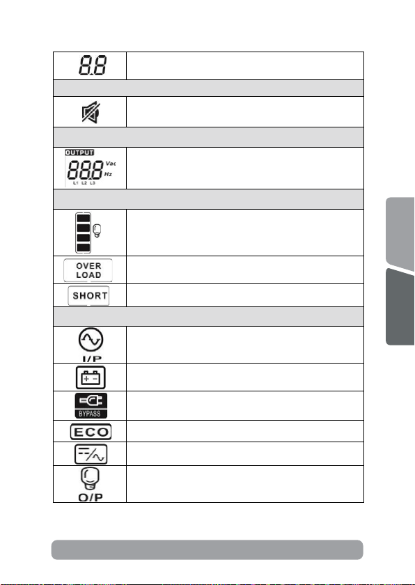
4) When the UPS is overload, please remove some loads immediately.
It is recommended to have the total loads connected to the UPS less than
80% of its nominal power capacity to prevent overload for system safety.
5) If the overload me is over acceptable me listed in spec in AC
mode, the UPS will automacally transfer to Bypass mode. Aer the
overload is resolved, it will return back to AC mode. If the overload me
is over acceptable me listed in spec in Baery mode, the UPS will enter
fault status. At this me, if bypass is enabled, the UPS will power to the
load via bypass. If bypass funcon is disabled or the input power is not
within bypass acceptable range, it will cut o output enrely.
4. Charge the baeries
1) Aer the UPS is connected to the mains and turned on in AC
mode, the charger will charge the baeries automacally except in baery
mode, during baery self-test, overload or when baery voltage is high.
2) It’s recommended to charge baeries for at least 10 hours before
operaon. Otherwise, the backup me may be shorter than expectaon.
5. Baery mode operaon
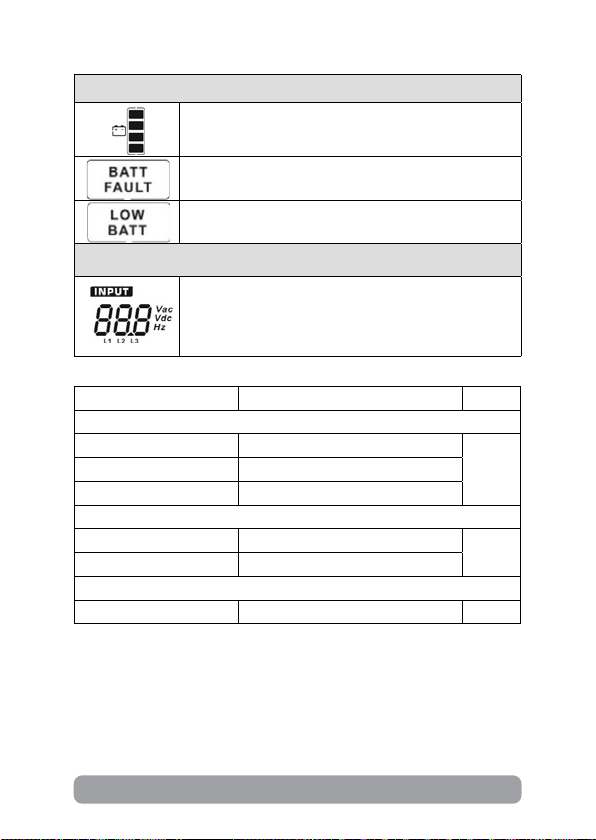
1) When the UPS is in Baery mode, the buzzer will sound according
to dierent baery capacity. If the baery capacity is more than 25%,
the buzzer will beep once every 4 seconds. If the baery voltage drops
to the alarm level, the buzzer will beep once every sec to remind users
that the baery is at low level and the UPS will shut down immediately.
Users could switch o some non-crical loads to disable the shutdown
alarm and prolong the backup me. If there is no more load to be switched
o, you have to prepare shutdown procedure to protect working data or
devices. Otherwise, there is a risk of data loss or load failure.
2) In Baery mode, users can press the Mute buon to disable the
buzzer.
3) The backup me of the long-run model depends on the external
baery capacity.
4) The backup me may vary from dierent operang temperature
and load type.
5) When seng backup me for 16.5 hours (default value from LCD

17
English
Română
menu), aer discharging 16.5 hours, UPS will shut down automacally to
protect the baery. This baery discharge protecon can be enabled or
disabled through LCD menu. (Refer to 3-7 for details).
6. Test the baeries
1) If you need to check the baery status when the UPS is running in
AC mode/CVCF mode, you could press the “Test” buon for baery self-
test.
2) Users also can set baery self-test through monitoring soware.
7. Turn o the UPS with ulity power supply in AC mode
1) Turn o the inverter of the UPS by pressing “OFF” buon for at
least 0.5s, and then the buzzer will sound once. The UPS will enter into
Bypass mode.
NOTE 1: If the UPS has been set to bypass output, it will bypass voltage
from the mains to output terminal even though you have turned o the
UPS (inverter).
NOTE 2: Aer turning o the UPS, please be aware that the UPS is
working in Bypass mode, there will be risk of power loss for connected
devices.
2) In Bypass mode, output voltage of the UPS is sll present. In order
to cut o the output, switch o the line input breaker. The LCD display will
turn o and UPS is now completely o.
8. Turn o the UPS without ulity power supply in Baery mode
1) Turn o the UPS by pressing “OFF” buon for at least 0.5s, and
then the buzzer will sound once.
2) Then, UPS will cut o power to output terminals and there will no
display shown on the LCD panel.
9. Mute the buzzer
1) To mute the buzzer, please press the “Mute” buon for at least 0.5s.
If you press it again aer the buzzer is muted, the buzzing will resume.

18
2) Some warning alarms can’t be muted unless the error is xed.
Please refer to secon 3-3 for details.
10. Operaon in warning status
1) When Fault LED illuminates and the buzzer beeps once every
second, it indicates that there are problems for UPS operaon. Users can
read the warning message(s) from LCD menu. Please refer to the Chapter
4 for details.
2) Some warning alarms can’t be muted unless the error is xed.
Please refer to secon 3-3 for details.
11. Operaon in Fault mode
1) When Fault LED illuminates and the buzzer beeps connuously, it
means that there is a fatal error with the UPS. Users can get the fault code
from LCD menu. Please refer to the Chapter 4 for details.
2) Please check the loads, wiring, venlaon, mains, baery and so on
aer the fault occurs. Don’t try to turn on the UPS again before solving the
issues. If the problems persist, contact the distributor or service personnel
immediately.
3) In case of an emergency, shut o connecons from mains, external
baery, and output immediately to avoid possible damage to the UPS or
equipment.
12. Operaon in maintenance mode
This operaon should only be performed by maintenance personnel or
qualied technicians.
When the UPS needs to repair or service and the load could not be shut
o, the UPS needs to be put into maintenance mode.
1) First, switch o the UPS.
2) Then, remove the cover of maintenance bypass switch on the
panel.
3) Turn the maintenance switch to “BPS” posion. Then, turn o the
UPS input breaker and output breaker.

19
English
Română
13. Operaon in changing baery quanty
1) This operaon should only be performed by maintenance personnel
or qualied technicians.
2) Turn o the UPS. If the load cannot be shut o, you should remove
the cover of maintenance bypass switch on the panel and turn the
maintenance switch to “BPS” posion.
3) Switch o the line input breaker and external bypass input breaker.
Then, UPS will enter into “No Output mode”.
4) Connect communicaon cable to the UPS and a computer. Be
sure to install communicaon tool rst. For this soware tool, please
check your local dealer for the details. Use the soware to set up baery
quanty accordingly. Or use LCD seng interface to set the baery
quanty directly, please contact with the local aer-sales service.
5) Aer sengs are updated successfully, shut down the UPS with
baery connected to save the changes. Then, modify the connected
baery pack numbers accordingly.
6) Switch on the ulity power breaker and external bypass input
breaker. Then, the UPS will enter into bypass mode. If the UPS is in
maintenance bypass mode, turn the maintenance switch back to “UPS”
posion and then turn on the UPS.
NOTE!
If you see warning code “01”, the UPS is not able to set up the baery quanty.
Only in No output mode can baery quanty be modied.
14. Operaon in seng charging current
1) This operaon should only be performed by maintenance personnel
or qualied technicians.
2) Connect communicaon cable to the UPS and a computer. Be sure
to install communicaon tool rst. For this soware tool, please check
your local dealer for the details. Use the soware to set up charging
current accordingly. Or use LCD seng interface to set charge current
directly. Please refer to Program 21 in LCD seng secon (3-7).
3) Aer sengs are updated successfully, the updated charging
current will take eect immediately. The UPS would need to be restarted

20
NOTE!
The charger quanty seng must coincide with actual number installed in the
UPS. If the seng quanty is more than actual installed quanty, the charging
current will not meet the specicaon.
1. Parallel system inial startup
Please make sure that all of the running UPSs are parallel models and have
the same conguraon.
1) Turn on each UPS in AC mode respecvely (Refer to secon 3-4(1).
Then, measure the inverter output voltage of each phase for each UPS
with a mul-meter. Calibrate the inverter output voltage by conguring
inverter voltage adjustment (Refer to Program 15, 16 and 17 in secon
3-7) in LCD menu unl the inverter output voltage dierence of each UPS
is within 1V or less.
2) Calibrate the output voltage measurement by conguring output
voltage calibraon (Refer to Program 18,19, and 20, secon 3-7) in LCD
seng to make sure the dierence between real output voltage and
detected value of UPS is less than 1V.
3) Turn o each UPS (Refer to secon 3-4(7.). Then, follow the wiring
procedure in secon 2-4.
3.5 Parallel Operaon
to saving the seng.
15. Operaon in seng charger quanty
1) This operaon should only be performed by maintenance personnel
or qualied technicians.
2) Turn o the UPS. If the load can not be cut o, you should remove
the cover of maintenance bypass switch on the panel and turn the
maintenance switch to “BPS” posion.
3) Switch o the line input breaker and UPS will enter into “No
Output mode”.
4) Connect communicaon cable to the UPS and a computer. Be sure
to install communicaon tool rst. For this soware tool, please
This manual suits for next models
1
Table of contents
Languages:
Other Njoy UPS manuals

Njoy
Njoy Token Series User manual

Njoy
Njoy Renton 650 User manual

Njoy
Njoy Soter 600 User manual

Njoy
Njoy Ranger Series User manual

Njoy
Njoy Echo Pro Series User manual

Njoy
Njoy Code Series User manual

Njoy
Njoy Aira 600 User manual

Njoy
Njoy UPCMTOP960HASCG02B User manual

Njoy
Njoy PWUP-LI060HR-AZ01B User manual

Njoy
Njoy Soter 600 User manual

Njoy
Njoy PWUP-LI060H1-AZ01B User manual

Njoy
Njoy Aster 6KT User manual

Njoy
Njoy Shed 625 User manual

Njoy
Njoy Ranger Series User manual

Njoy
Njoy Aster Series User manual

Njoy
Njoy PWAV-10001AK-AZ01B User manual

Njoy
Njoy Alvis Series User manual

Njoy
Njoy Balder Series User manual

Njoy
Njoy Aster Series User manual

Njoy
Njoy Eido 600 User manual