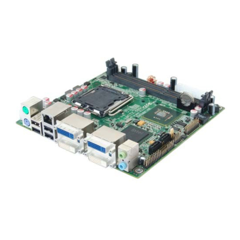
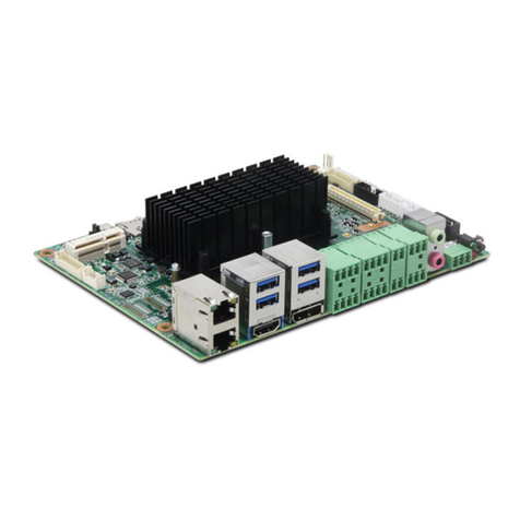
Norco MITX-6854 User manual

MITX-6854
Mini-ITX Industrial Motherboard
USER' Manual V1.1

ShenZhen NORCO Intelligent Technology Co., Ltd.:0755-27331166
Beijing:010-82671166
Shanghai:021-61212088
Nanjing: 025-58015489
Chengdu:028-85259319
Shenyang:024-23960846
Xi’an:029-88338386
Nanjing: 025-58015489
Wuhan:027-87858983
Tianjin:022-23727100
Singapore:65-68530809
Netherlands:31-040-2668554
Web:www.norco.cn
MITX-6854
Mini-ITX Industrial Motherboard
USER' Manual V1.1

MIT
X
-6854 Mini-IT
X
Industrial Motherboard
Place/Data: HONG KONG/2008
ShenZhen NORCO Intelligent Technology Co.,Ltd.

Data: 2009
Trade Name:ShenZhen NORCO Intelligent Technology Co.,Ltd.
Model Name:MITX-6854
Responsible Party:ShenZhen NORCO Intelligent Technology Co.,Ltd.
Equipment Classification:FCC Class B Subassembly
Type of Product:Mini-ITX Industrial Motherboard
Manufacturer:ShenZhen NORCO Intelligent Technology Co.,Ltd.

Copyright
With the exception of showing the accessories of product configuration,
this manual do not create any commitment of our company. We retained the
rights to change it without prior notice. We will not be responsible for any
installation, the result of improper use of direct, indirect, intentional or
unintentional damage or hidden dangers.
Before buying products, please learn about product performance from
the seller to see if it is in line with your needs. NORCO is a registered
trademark of Shenzhen NORCO Intelligent Technology CO.,Ltd. Other
trademarks involved in this manual, their ownership are owned by its
respective owners. The contents of this manual are protected by copyright
law. All rights are strictly reserved. Any form of unauthorized reproduction
including but not limited to carbon copy, facsimile transmission and
electronic copy or email should be destroyed immediately.

Common Sense in Safety Application
1. Before using this product, be sure to read carefully this user’s manual;
2. Any plate cards not ready to be installed shall be kept in the anti-static
protective bags;
3. Before taking out the plate cards from the anti-static protective bags, first
place hands on the grounding metal object for a while (e.g. 10 seconds) so
as to release static electricity in body and hands;
4. While fetching plate cards, you should wear static protective gloves and
have the habit of contacting brims of them;
5. In order to prevent bodily electric shock or damage to products, first turn
off the AC power or unplug the power cord out of power sockets while
inserting main boards or plate cards or configuring again;
6. Before it is necessary to move plate cards or the unit, be sure to unplug
the AC power cords out of the power sockets;
7. Be sure to unplug AC power cords when there is an increase/decrease in
plate cards for this product;
8. Before you connect or unplug any equipment, be sure to determine
whether all power cords are unplugged in advance;
9. To prevent any unnecessary injuries to products due to frequent power
on/off to the products, after the unit is shut down, you must wait at least 30
seconds before you restart up the unit.
10: If anything unexpected exists during Equipment used, please contact
the professionals.

Contents
Chapter1 General Information............................................................................ 1
1.1 Introduction ................................................................................................................. 1
1.2 Specifications..............................................................................................................1
Chapter2 Installation Instructions..................................................................... 4
2.1 Connector Locations and Dimensions ........................................................................ 4
2.2 Installation Steps......................................................................................................... 5
2.3 Installing SO-DIMM..................................................................................................... 6
2.4 Setting Jumpers.......................................................................................................... 6
2.4.1 Clear CMOS (JCC) .................................................................................................. 6
2.4.2 COM2 setting(J5,J6,J7)................................................................................. 8
2.4.3 CF Card Master/Slave Selection(JCF)................................................................ 9
2.4.4 LCD Power Selection(J8).................................................................................. 10
2.5 External Connector ................................................................................................... 11
2.5.1 IDE Connector(IDE1)........................................................................................ 11
2.5.2 SATA Connector&SATA Power Connector(SATA0,SATA1,S_PWR)............ 12
2.5.3 CF Card Socket(Compact Flash)...................................................................... 13
2.5.4 Parallel Por(LPT).............................................................................................. 13
2.5.5 Serial Port(COM1,COM2,COM3-6,COM7-10).................................................. 14
2.5.7 LVDS PANEL BACKLIGHT(J9)......................................................................... 20
2.5.8 USB&Ethernet(USB_RJ,USB_12,USB_34,USB_56)....................................... 20
2.5.9 Keyboard/Mouse connector(PS/2).................................................................... 22
2.5.10 IRDA interface(IRDA)...................................................................................... 23
2.5.11 GPIO(J10)....................................................................................................... 24
2.5.12 Power Connectors (ATX,DC_JACK) ................................................................. 25
2.5.13 CPUFAN connector(CPUFAN)........................................................................ 26
2.5.14 Audio (JACK_HDA).............................................................................................. 27
2.5.15 Front Panel connector(J4).............................................................................. 29
2.5.16 RAM Slot(SODIMM)........................................................................................ 31
2.5.17 PCI Slot(PCI).................................................................................................. 32

2.5.18 Mini PCIE(MINI_PCIE,W_LED)...................................................................... 33
Chapter3 BIOS Setup............................................................................................... 34
3.1 Standard CMOS Setup ............................................................................................. 35
3.2 Advanced BIOS Features ......................................................................................... 38
3.2.1 CPU Feature.......................................................................................................... 38
3.2.2 Removable Device Priority .................................................................................... 40
3.2.3 Hard Disk Boot Priority .......................................................................................... 40
3.2.4 CD-ROM Boot Priority ........................................................................................... 41
3.3 Advanced Chipset Features...................................................................................... 44
3.4 Integrated peripherals............................................................................................... 47
3.4.1 OnChip IDE Device................................................................................................ 48
3.4.2 Onboard Device..................................................................................................... 49
3.4.3 Super IO Device .................................................................................................... 50
3.4.4 F81216D[COM3-COM10] ...................................................................................... 53
3.4.5 USB Device Setting ............................................................................................... 55
3.5 Power Management Setup ....................................................................................... 56
3.6 PnP/PCI Configurations............................................................................................ 59
3.7 PC Health Status ...................................................................................................... 60
3.8 Frequency/Voltage Control ....................................................................................... 62
3.9 Load Fail-Safe Defaults ............................................................................................ 62
3.10 Load Optimized Defaults ........................................................................................ 63
3.11 Set Supervisor Password........................................................................................ 64
3.12 Set User Password ................................................................................................. 64
3.13 ave&Exit Setup ....................................................................................................... 65
3.14 Exit Without Saving................................................................................................. 65
Appendix........................................................................................................................... 67
Appendix 1: Driver Installation ........................................................................................ 67
Appendix 2:Watchdog programmer guide.................................................................... 68
Appendix3:GPIO Instruction......................................................................................... 70
Appendix 4: Glossary...................................................................................................... 71

Packing List
Thank you very much for choosing our products. Please check your package
completely as the following item checklist first, if you find any components lost or
damaged, please contact your retailer.
■MITX-6854 motherboard
■NORCO-4134 PCI convert Card(Optional)
■User’s Manual
■Drive Disk
■SATA Data Cable
■SATA HD Power Cable (optional)
■IDE Data Cable
■Serial port convert cable(2x20Pin convert 4 DB9)
■LPT convert cable
■USB convert cable
■Jumpers
1pcs
1 pcs
1 pcs
1 pcs
1 pcs
1 pcs
1 pcs
2 pcs
1 pcs
1 pcs
4 pcs

Chapter 1
General Information

MITX-6854 Mini-ITX Fanless Motherboard Based on ATOM Processor
1
Chapter1 General Information
1.1 Introduction
MITX-6854 is fanless Mini-ITX motherboard based on Intel 945GSE+ICH7M chipset with
integrated Intel Atom N270 1.6GHZ CPU(FSB 533MHz and L2 Cache 512KB).MITX-6854 has
One 200 pin SO-DIMM DDRII 400/533MHz socket support system memory max. upto
2GB.With integrated graphic controller in northbridge, MITX-6854 is also provide
VGA/DVI/LVDS display and Dual-Independent-Display(VGA+DVI or VGA+LVDS).MITX-6854
provides one IDE, two SATAII, eight USB2.0, ten COM and one GbE (PCI-E). Additionally, one
PCI and one mini-PCIE are also provided for the system flexibility.
MITX-6854 is an integrated powerful computing platform with standard digital input/out
ports 、IrDA ,Watchdog Timer. It is specially suitable for POS 、kiosk 、ATM and Rail
Transportation applications.
1.2 Specifications
Configuration Standard
●Low consume Mini-ITX Standard motherboard
Dimensions
●170mm X 170mm(L×W)
Processor
●Onboard Intel Atom N270 1.6G processor ,L2 for 512KB,Power consumption is only
2.5W.Support FSB for 533MHz
●Support EM64T
Chipset
●North Bridge:Intel®945GSE(TDP 5.5~6W)
●South Bridge:Intel ®ICH7M
Display
●Chipset:Intel®945GSE Graphics Memory Controller Hub (GMA950)
●VGA:1x DB15 port,support uXGA and resolution up to 2048x1536

MITX-6854 Mini-ITX Fanless Motherboard Based on ATOM Processor
2
●DVI(Optional):SDVO signal convert DVI signal,Support resolution up to 1600x1200(DVI
and LVDS combination not included),
●LVDS(Optional):SDVO signal convert 24bit LVDS signal,Support resolution up to1600x1200,
GPIO Brightness control,Backlight power control.(DVI and LVDS combination not included)
●Dual Independent Display:VGA+LVDS/VGA+DVI can support dual independent display (DVI
and LVDS combination not included)
System Mermory
●1x 200Pin dual channels SODIMM Memory socket
●Support DDRⅡ400/533MHz memory Up to 2GB
Storage
●2x Serial ATAⅡPorts, The transfer speed is up to 300MB/s
●1x IDE Port,Support PIO、Bus Master、Ultra DMA33/66/100 mode,The transfer speed is up
to 100MB/s
●Compact Flash:50Pin Socket(Support DMA Mode),Share IDE channels
LAN
●Chipset: REALTEK 8111C
●Speed: 10/100/1000Mbps
●Interface:1x RJ45 Port
Audio
●Chipset: ALC888
●Audio Controller: Supports AC97 Audio stereo sound
●Audio Interface:Line-out,MIC-IN
USB Port
●8x USB2.0 ports,The transfer speed is up to 480Mb/s
●Back panel double USB ports
●3 group 2x5Header ports,can convert to 6x stanard USB ports

MITX-6854 Mini-ITX Fanless Motherboard Based on ATOM Processor
3
I/0 Functions
●Use Winbond W83627HF I/O chip
●Support 10x Serial Ports,COM1、COM2(by I/O chipshet) double deck DB9 ports,COM1
support RS232 ,COM2 support RS232\422\485 ;Through the LPC bus Extended
COM3-COM10 (by F81216 chipshet),support RS232。
●Provides one 2x10Pin parallel Port, Support SPP/EPP/ECP mode
●standard PS/2 keyboard and mouse port
●1x IrDA Port
●Programmable input/output interfaces
Expansion Interfaces
●1x PCI Slot
●1x Miini-PCIE Slot
Power support
●Single power input (+12V)/ Standard ATX PowerSupply
Watchdog
●Support H/W reset function
BIOS
●8MB SPI Flash BIOS
●Support ACPI Power manage
Environmental
●Operate Temp:0-60℃
●Storage Temp.:-40-85℃
●Operating Humidity::5%-95%

Chapter 2
Installation Instructions

MITX-6854 Mini-ITX Fanless Motherboard Based on ATOM Processor
4
Chapter2 Installation Instructions
2.1 Connector Locations and Dimensions
The following picture is interface index for MITX-6854, when you install your devices,
please consult it and read the following guide. During installation please care: for some devices,
if incorrectly install, it will not work normally.
Note:During installation, in order to protect the part of board, please put on antistatic gloves。
MITX-6854 Connectors Locations

MITX-6854 Mini-ITX Fanless Motherboard Based on ATOM Processor
5
MITX-6854 Dimensions
2.2 Installation Steps
Please refer to the following steps to install your computer:
1. Adjust all Jumpers on the MITX-6854 per this manual.
2. Installing system memory
3. Installing Expansion card
4. Connect all of the signal line, cable, panel-control circuitry and power supply
5. Finish BIOS setup
Note:
Key components of this motherboard are Integrated circuit, and these components will be
easily damaged by electrostatic influence. So, before installing motherboard, you should
always follow the following precautions:
1. Disconnect your Computer from the power supply before handling it.
2. Hold side by the edges; don't touch any component or pins on the board

MITX-6854 Mini-ITX Fanless Motherboard Based on ATOM Processor
6
3. Use a grounded wrist strap while getting in touch with integrated circuit component (like
as CPU, RAM).
4. Place components on a grounded antistatic bag that came with the Single Board
Computer, when these components are separated from the system.
2.3 Installing SO-DIMM
The procedures for installing SODIMM are described below. Please follow these steps
carefully. You can install SDRAM memory modules using 200-pin SODIMM (Small Outline Dual
In-line Memory Modules).
1:Ensure that all power supplies to the system are switched off.
2:Tilt the SODIMM card approximately 25° above the board, and move it in the direction of the
housing card slot. Make sure that the key in the module and the key in the housing are aligned.
3:Push the module into the socket until the module bottoms. There should be a slight insertion
force to engage the module into the contacts.
2.4 Setting Jumpers
Note:
Jumpers are located on the motherboard, they represent clear CMOS jumper JCC etc.
pin1 for all jumpers are located on the side with a thick white line refer to the motherboard’s
silkscreen , jumpers with three pins will be shown as 1-2 to represent pin1&pin2 connected and
2-3 to represent pin2&pin3 connected.
2.4.1 Clear CMOS (JCC)
This jumper is used to erase CMOS data and reset system BIOS information.The
procedure for clearing CMOS is:
1. Turn off the system.
2: Move the jumper cap from pins 1-2 (default) to pins 2-3. Keep the cap on pins 2-3 for about
5~10 seconds, then move the cap back to pins 1-2.
3. Turn on the system. The BIOS is now reset to its default setting

MITX-6854 Mini-ITX Fanless Motherboard Based on ATOM Processor
7
setting JCC
1-2 Clear CMOS(BIOS renew to initialization)
2-3 Nomal status(default)
Do not clear CMOS when power switch on, or it harm to the motherboard.

MITX-6854 Mini-ITX Fanless Motherboard Based on ATOM Processor
8
2.4.2 COM2 setting(J5,J6,J7)
COM2 can be configured to operate in RS-232, RS-422, or RS-485 mode (RS232 for
default.). This is done via J5、J6 and J7.
COM2 RS232(default)COM2 RS422 COM2 RS485
J5 3-5 4-6 J5 1-3 2-4 J5 1-3 2-4
J6 3-5 4-6 J6 1-3 2-4 J6 1-3 2-4
J7 1-2 J7 3-4 J7 5-6 7-8

MITX-6854 Mini-ITX Fanless Motherboard Based on ATOM Processor
9
2.4.3 CF Card Master/Slave Selection(JCF)
This jumper for setting CF card as master or slave, close JCF jumper (plug JCF cover), CF
card is set as master. When you need to set it as slave, open the cover please! Master for
default.
Setting JCF
Close Set CF card as master(default)
Open Set CF card as slaver
Other manuals for MITX-6854
1
Table of contents
Other Norco Motherboard manuals

Norco
Norco MITX-6110 User manual

Norco
Norco EMB-3682 User manual

Norco
Norco MITX-6922 User manual

Norco
Norco MITX-6934 User manual

Norco
Norco EMB-4850 User manual

Norco
Norco SOM-6503 User manual

Norco
Norco BPC-7971 User manual

Norco
Norco EMB-3503 User manual

Norco
Norco EMB-7536 User manual

Norco
Norco MITX-6946 User manual

Norco
Norco EMB-2510 User manual

Norco
Norco POS-7893 User manual

Norco
Norco MITX-6973 User manual

Norco
Norco MITX-6891 User manual

Norco
Norco BPC-7934 User manual

Norco
Norco EMB-7540 User manual

Norco
Norco SOMB-073 User manual

Norco
Norco MITX-6910 User manual

Norco
Norco BPC-7936 User manual

Norco
Norco FWMB-7550 User manual