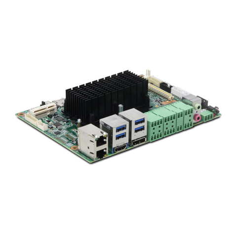
Norco MITX-6930 User manual

MITX-6930
Mini-ITXMotherboard
UserManual V1.0

Announcement
Withtheexception oftheaccessorieslistedintheproductconfiguration, thismanual
doesnotcreateanycommitmentofourcompany. Weretainedtherightstochangeit
withoutpriornoticeandwill notberesponsibleforanydirect,indirect,intentionalor
unintentionaldamageorhiddendangerscausedbyanyimproperinstallationoruse.
Beforeorderingproducts,pleaselearnabouttheproductperformancefromthe
distributorstosee if it isinlinewithyourneeds.NORCO isaregisteredtrademarkof
ShenzhenNORCOIntelligentTechnologyCO.,LTD.Theownershipofother
trademarksinvolvedinthismanualisownedbyitsrespectiveowners.Thecontents
ofthismanualareprotectedbycopyrightlaw.Allrightsarestrictlyreserved.Any
formof unauthorizedreproductionincludingbut notlimited tocarboncopy,facsimile
transmissionandelectroniccopyoremailisprohibited.

SafetyInstructions
1. Beforeusing thisproduct,pleaseread thisuser smanualcarefully;
2. Anyplatecardsnotreadytobeinstalledshallbekeptinthe anti-staticbags;
3. Beforetakingouttheplatecardsfromtheanti-staticbags,firstplace
handson thegroundingmetalobject forawhilesoastoreleasethestaticelectricity
fromyourbodyandhands;
4.Whilefetching theplatecards,pleasewearstaticprotectiveglovesandhavethe
habit ofholding thecardsbyedges;
5.Beforeconnecting themotherboardtothepowersupply,pleasecheck thepower
voltage
6.Inordertopreventelectricshocktobodyordamagetoproducts,pleaseturnoff
theACpowerorunplug thepowercordoutofpowersocketsbeforeconnectingor
disconnecting themainboardsordoreconfiguration;
7. Beforemovingtheplatecardsortheunit, pleasemakesuretounplugtheAC
powercordsoutofthesockets;
8. Beforeyouconnectorunpluganyequipments,pleasemakesurethatall
powercordsareunpluggedinadvance;
9.Toprevent anyunnecessarydamagetotheproductsduetofrequentpoweron/off.
Pleasewaitatleast30 secondsbeforeyourestart theunitaftershutdown.
10.Ifanythingunexpectedhappenedduringtheoperating,pleaseseekhelpfrom
professionals.

Content
Chapter1Product Introduction......................................................................................................1
1.1Overview...........................................................................................................................1
1.2Specification......................................................................................................................1
Chapter2Installation Instructions.................................................................................................4
2.1InterfacesLocation andDimensions................................................................................4
2.2InstallationSteps...............................................................................................................5
2.3Install DIMM......................................................................................................................5
2.4JumperSetting..................................................................................................................5
2.4.1CMOSContent Clearance/Hold Setting JCC)..................................................5
2.4.2AutoStart Upon ACPowerRestoreSwitch JAT).............................................7
2.4.3COM2JumperSetting J5, J6, J8)....................................................................7
2.4.4 LVDSRated PowerSelect Jumper JP1, JP2).................................................8
2.4.5 PCIVIOVoltageSelect Jumper JP5)............................................................10
2.5InterfaceDescription....................................................................................................10
2.5.1 SATA SATA1, SATA2)....................................................................................10
2.5.2Serial Ports COM1, COM2, COM3-COM6)....................................................11
2.5.3Display VGA, DVI, LVDS)...............................................................................14
2.5.4USB_LAN USB_LAN1,USB_LAN2,USB_56)...........................................15
2.5.5KB/MS KBMS).................................................................................................17
2.5.6GPIO J7)..........................................................................................................17
2.5.7PowerInterface ATX)......................................................................................19
2.5.8FANConnector CPUFAN)..............................................................................20
2.5.9Audio Audio、JAU).........................................................................................20
2.5.10Parallel Port LPT)..........................................................................................21
2.5.11 LPC J16).......................................................................................................23
2.5.12 LVDSPowerVoltage J2)..............................................................................24
2.5.13Front Panel Connector JFP).........................................................................24
2.5.14DIMMSlot DIMM)..........................................................................................26
2.5.15 PCI Slot..............................................................................................................26
2.5.16 MINI PCIE MINIPCIE1,MINI PCIE2,J3, J4)..............................................26
Chapter3BIOSSetup...............................................................................................................27
AMIBIOSUpgrading............................................................................................................27
AMIBIOSDescription...........................................................................................................27
BIOSParameterSetting.......................................................................................................27
3.1 Main Menu.....................................................................................................................28
3.2 Advanced Menu.............................................................................................................29
3.2.1 ACPI Settings......................................................................................................29
3.2.2 APMConfiguration..............................................................................................30
3.2.3 CPUConfiguration..............................................................................................31
3.2.4 IDEConfiguration................................................................................................32
3.2.5 USBConfiguration...............................................................................................33
3.2.6 SupperIOConfiguration.....................................................................................34
3.2.7 H/WMonitor.........................................................................................................35
3.3 ChipsetMenu.................................................................................................................36
3.3.1 NorthBridge.........................................................................................................36
3.3.2 SouthBridge........................................................................................................37
3.4 Boot Menu......................................................................................................................38
3.5 SecurityMenu................................................................................................................40
3.6 Save&ExitMenu..........................................................................................................41
Appendix.......................................................................................................................................42
Appendix1:Watchdog Programming Guide......................................................................42
Appendix2:Glossary..........................................................................................................42

Chapter1. Product
Introduction

MITX-6930 Intel NM10BasedMini-ITXMotherboardwith3GConnectivity
1
Chapter1Product Introduction
1.1Overview
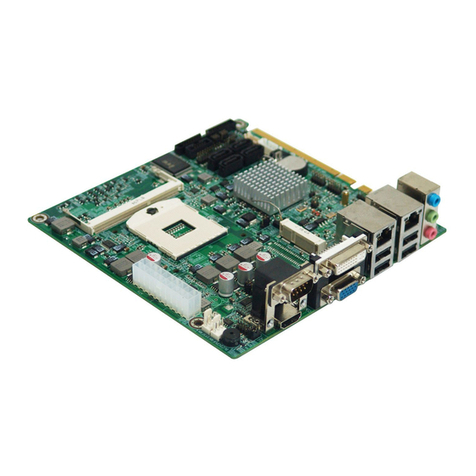
MITX-6930 isatypeofmini-ITXembeddedboardbased ontheIntelNM10Chipsetand
equipped withthenextgenerationdual coreIntel AtomN2800orD2700processor.The
environmentallyresponsibleembedded boardsolutionexceedsitspredecessorsinboth
performancespeed andgraphics capabilityalltooffergreaterscalabilityinasmallerfootprint
fanless solution.Deliveringenhanced performance,clearergraphics,responsiveness,
embeddedlifecycle,andenablingconnectivity,theMITX-6930isadesigned solution targeted
atdigitalsignage,POS,kiosks,enterprisesecurity,digital surveillance,medicine,andfactory
automation.
1.2Specification
StructureStandards
●Mini-ITXMotherboard
Dimension
●170mm×170mm L×W)
Processor
●OnboardIntel ®AtomN2800/D2700 Processors
Chipset
●Intel®NM10
Display
●DisplayChip:Chipsetintegrated
●VGA:1xDB15VGAwithresolution upto1920×1200@60Hz
●DVI: DVI-DsupportsHDMIvideo out,withresolution upto1920×1200@60Hz
●LVDS: N2000series 18Bit1366×768@60Hz);D2000series 24Bit1440×900@60Hz)
SystemMemory
●1xsinglechannel SO-DIMMslot supportsDDRIII 1066upto4GB

MITX-6930 Intel NM10BasedMini-ITXMotherboardwith3GConnectivity
2
Storage
●2xstandard7Pin SATA
LAN
●LANController:AdoptsIntel 82574LEthernetChip
●Provide2xUSB2.0and1xRJ45
●SupportWake-on-LAN WOL)
●Rate:10/100/1000Mbps
Audio
●AdoptALC887 7.1HD audiocontrollerchip
●Externalaudioporton therearpanel,blueforLine-in, GreenforLine-out ,Red forMic-in
●InbuiltAudioextentsion Pin.One2x5Pin header,offering1xLine-in,1xLine-outand1x
Mic-in
USB
●Rearpanel with2xdoublelayerUSBinterface,offering4xstandardUSB ports.
●Provideone2×5Pin USB Pin, converted to2xstandardUSB ports
I/O
AdoptITE8783FI/OChip
●6xCOM.COM1-2isthestandardDB9interface.COM3-6is2×20Pininterface,toconnect
deviceswithan enxtensioncable. COM1-COM6support RS232.COM2alsosupports
RS422\485.
●Provideone2×4Pin keyboard/mouseinterface
●Providesone2×5PinGPIOinterface
●Parallel Port:one2×10Pininterface,toconnectparallel deviceswithan extension cable,
supportingSPP/EPP/ECPMode
Expansions
●2xMINI PCIe, 1xMINI PCIeSSDandMINIPCIe2supportsSIMBusinterface
●OnboardSIMcardslot forMINIPCIe3Gmodule,offering 3Gconnectivity

MITX-6930 Intel NM10BasedMini-ITXMotherboardwith3GConnectivity
3
●1xstandardPCI Slot
●Provideone2×10PinLPCport
PowerSupply
●StandardATXpowersupply
Watchdog
●Support systemreset function
BIOS
●2MBSPI BIOS
Environment
●OperatingTemperature: 0 ~60
●StorageTemperature:-40 ~85
●OperatingHumidity: 5%~95%, no-condensing

Chapter2. Installation
Instructions

MITX-6930 Intel CedarTrail Based Mini-ITXMotherboardwith3GConnectivity
4
Chapter2Installation Instructions
2.1InterfacesLocation and Dimensions
FollowingisthedimensiondiagramandtheinterfacelocationindexofMITX-6930.Please
followthisdiagramandtheinstructionsbelowtoinstallyourdevice.Theimproperinstallationof
anycomponentswillleadtosystemmalfunction.
Remark:Pleasewearanti-staticglovestohandlethisunitincase ofelectrostatic
damage.
MITX-6930DimensionDiagram

MITX-6930 Intel CedarTrail Based Mini-ITXMotherboardwith3GConnectivity
5
2.2Installation Steps
Pleasefollowthestepsbelowtoinstallyourcomputer:
1. Pleaseadjustalljumperson MITX-6930bytheusermanual
2. InstallDIMM
3. InstallExpansion Cards
4. Connectallsignal lines, cables, panelcontrol circuitandpowersupplymodule
5.Start yourcomputerandcompletetheBIOSsetting
KeycomponentsofthismotherboardareIntegratedcircuit,and thesecomponents
couldbeeasilydamagedbyelectrostaticinfluence.So,beforeinstalling thisunit, please
always keep thefollowingprecautionsinmind:
1. Holdtheboardbyedges,don ttouchanycomponentsorplugand socketpins
2.Wearanti-staticgloves/wriststrapwhiletouchingtheintegrated circuitcomponents,suchas
CPU, RAM,etc.
3.Put thoseunusedoruninstalledcomponentsinstaticshieldingbagsortrays
4.Pleasefirst checkthepowerswitchisoffbeforeconnectingthepowerplug
2.3Install DIMM
Onboard1xDIMMslots,pleasekeepfollowingpointsinmind when installingmemorybank:
1.When installingmemorybank, pleasealign itsnotchwiththealignmentmarkon thesocket
andthen press thememorybankslolwyintothesocket.
2. Pleasechoosekthememorybanksthatmatching yourmotherboard
2.4JumperSetting
Pleaserefertothefollowingjumpersettingguidebeforeinstallingyourhardwaredevices
installation.
Remark: HowtoidentifyjumperandPIN1of interface: Pleaseobservethewordmarkofplug
socket, itwill use “1”orboldlineortriangularsymbols;And pleaselookat thebackofPCB,
eachinterfaceweldspothasasquarepoint,whichisPIN1;andall thejumperPIN1havea
whitearrowon theside.
2.4.1 CMOSContent Clearance/HoldSetting JCC)
CMOSispoweredbytheonboardbuttoncell.ClearCMOSwillleadtopermanent

MITX-6930 Intel CedarTrail Based Mini-ITXMotherboardwith3GConnectivity
6
elimination of previoussystemsettingsand backtotheoriginal systemsetting(factorydefault).
Steps: 1)Turnoffthecomputeranddisconnect thepowersupply
2)UseJumperCap shortJCC P1&P2for5~6 sec.Then restorethedefaultsetting
withPin2-3connected
3)Turnon thecomputer,then press “DEL”keytoenterBIOSsettingandload
optimized defaults.
4)SaveandExit
JCC:
Setting JCC
1-2 ClearCMOS,BIOSbacktotheinitialization (factorydefault)
2-3 NormalStatus,default
DonotclearCMOSwhen thecomputorispoweron, otherwise,itwillcause
damageto themotherboard!

MITX-6930 Intel CedarTrail Based Mini-ITXMotherboardwith3GConnectivity
7
2.4.2AutoStart Upon ACPowerRestoreSwitch JAT)
JAT:
Setting JAT
Open Unsupport theautostartuponpoweron
Close Autostartuponpoweron
2.4.3 COM2JumperSetting J5,J6,J8)
J5, J6, J8arejumpersusedtoset COM2transmission mode. COM2supports
RS-232/RS-422/RS-485. Default transmission modeisRS-232.

MITX-6930 Intel CedarTrail Based Mini-ITXMotherboardwith3GConnectivity
8
2.4.4 LVDSRatedPowerSelectJumper JP1,JP2)
Beforeusing theLVDS,pleasemakeclearaboutitsratedoperatingpowerandvoltage.
COM2RS232 default)
COM2RS422 COM2RS485
J5 1-32-4 J5 3-54-6 J5 3-54-6
J6 1-32-4 J6 3-54-6 J6 3-54-6
J8 1-2 J8 3-4 J8 5-67-8
J8
J6
J5

MITX-6930 Intel CedarTrail Based Mini-ITXMotherboardwith3GConnectivity
9
Setting 3.3V 5V 12V
JP1 1-2 2-3 ×
JP2 ××1-2

MITX-6930 Intel CedarTrail Based Mini-ITXMotherboardwith3GConnectivity
10
2.4.5 PCIVIOVoltageSelectJumper JP5)
JP5:
Setting JP5
1-2 5V
2-3 3.3V
note:Please firstmakeclearaboutthePCI VIOvoltagerequirements, thenadjustthe
correspondingjumper,otherwise,damagewillbecaused totheboard!
2.5Interface Description
Pleaseread thefollowinginstructionscarefullybeforeyou connecttheexternal
connectorsin caseof anydamagetothemotherboard.
2.5.1 SATA SATA1,SATA2)
Boardprovides2xSATAports.

MITX-6930 Intel CedarTrail Based Mini-ITXMotherboardwith3GConnectivity
11
SATA:
Pin Signal Name
1 GND
2 TX+
3 TX-
4 GND
5 RX-
6 RX+
7 GND
2.5.2SerialPorts COM1, COM2, COM3-COM6)
Boardprovides6xserial ports.COM1-2arethestandardDB9interface.COM3-6isthe2x
20Pin header,toconnectdeviceswithan extension cable.Userscan open orclosetheserial
portsorselectitsIRQorI/Oaddress byBIOSsetting.
COM1-COM6supportRS232.COM2alsosupportsRS422/485.UserscanselecttheCOM2
transmission modethrough BIOSsetting.DetailspleaserefertoChapter2-.4.3“COM2Jumper
Setting”.

MITX-6930 Intel CedarTrail Based Mini-ITXMotherboardwith3GConnectivity
12
COM1、COM2:
Pin Signal Name
1 DCD
2 RXD
3 TXD
4 DTR
5 GND
6 DSR
7 RTS
8 CTS
9 RI
COM2setasRS232/RS422/RS485,Pindefinesasbelow:
Pin RS232
Default)RS422 RS485
1 DCD TX- DATA-
2 DSR NC NC
3 RXD TX+ DATA+

MITX-6930 Intel CedarTrail Based Mini-ITXMotherboardwith3GConnectivity
13
4 RTS NC NC
5 TXD RX+ NC
6 CTS NC NC
7 DTR RX- NC
8 RI NC NC
9 GND GND GND
10 GND GND GND
COM3-6:
Signal Name Pin Signal Name
DCD3 1 2 DSR3
RXD3 3 4 RTS3
TXD3 5 6 CTS3
DTR3 7 8 RI3
GND 9 10 GND
DCD4 11 12 DSR4
RXD4 13 14 RTS4
TXD4 15 16 CTS4
DTR4 17 18 RI4
GND 19 20 GND
DCD5 21 22 DSR5
RXD5 23 24 RTS5
TXD5 25 26 CTS5
DTR5 27 28 RI5
GND 29 30 GND
DCD6 31 32 DSR3
RXD6 33 34 RTS6
TXD6 35 36 CTS6
DTR6 37 38 RI6
GND 39 40 GND
Table of contents
Other Norco Motherboard manuals

Norco
Norco MITX-6922 User manual

Norco
Norco EMB-7540 User manual

Norco
Norco SOMB-073 User manual

Norco
Norco EMB-4850 User manual

Norco
Norco MITX-6854 User manual

Norco
Norco BPC-7934 User manual

Norco
Norco FWMB-7550 User manual

Norco
Norco POS-7893 User manual

Norco
Norco MITX-6110 User manual

Norco
Norco EMB-3503 User manual

Norco
Norco MITX-6891 User manual

Norco
Norco MITX-6946 User manual

Norco
Norco BPC-7971 User manual

Norco
Norco SOM-6503 User manual

Norco
Norco BPC-7936 User manual

Norco
Norco MITX-6973 User manual

Norco
Norco EMB-7541 User manual

Norco
Norco MITX-6934 User manual

Norco
Norco MITX-6922 User manual

Norco
Norco ATX-6991 User manual