Norco FWMB-7550 User manual

FWMB-7550
Network Firewall Motherboard
User's Manual V1.0

Content
Chapter 1 Product Introduction..............................................................................................................1
1.1 Product Introduction..................................................................................................................1
1.2 Product Specification................................................................................................................ 1
Chapter 2 Hardware Function................................................................................................................3
2.1 Interface Location and Dimension Diagram..........................................................................3
2.2 Installation Steps....................................................................................................................... 3
2.2.1 Install CPU Fan Steps...........................................................................................................4
2.3 Interface Specification.............................................................................................................. 4
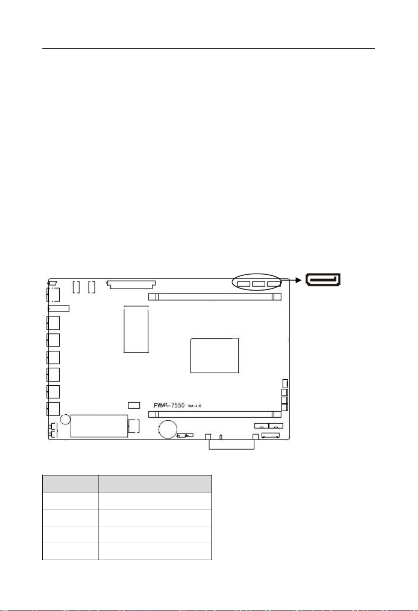
2.3.1 SATA Port(SATA1、SATA2、SATA3)................................................................ 4
2.3.2 USB Port(USB1、USB2、USB3、USB4)...........................................................5
2.3.3 Serial Communication Port(COM1_2、JGPIO、LPC).......................................5
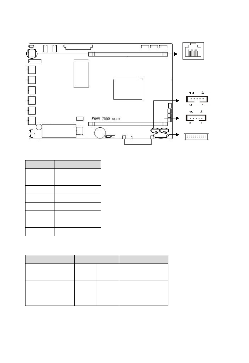
2.3.4 Ethernet Interface(LAN1、LAN2、LAN3、LAN4、LAN5、LAN6).................. 7
2.3.5 Fan Interface(CPUFAN,SYS_FAN1-3).............................................................. 7
2.3.6 Power Interface(PWR).............................................................................................8
2.3.7 Front Panel Interface(JFP)......................................................................................9
2.3.8 Motherboard Indicator.................................................................................................11
2.3.9 Memory Slot(DIMM)...............................................................................................11
2.3.10 PCIE_X8 Signal........................................................................................................ 12
2.3.11 Switch Key and Reset Key(PWRSW、RSISW).............................................12
Appendix 1:Glossary.................................................................................................................. 32

Chapter
One
Product
Introduc
tion

FWMB-7550 Network Firewall Motherboard
1
Chapter One Product Introduction
1.1 Introduction
FWMB-7550 is a network firewall motherboard,support Phytium FT1500A-16 core
processor,2x DIMM memory slot,and dual channel、DDRⅢ1066/1333,support ECC,
memory up to 16GB;Provide 1x RJ45 Console port、3x USB3.0 port、1x USB2.0 port、3x
SATA3.0、support 6x Gigabit RJ45 network port;1x standard MINIPCIE supports mSATA.
1.2 Product Specification
Structural standard
●Network Firewall Motherboard
Size
●300mm×200mm(L×W)
Processor
● Support Phytium FT1500a (16 core) processor
System memory
●2x DIMM memory slot,support dual channel、DDRⅢ1066/1333,and ECC,memory up
to 16GB
Storage
●3x standard 7 pin SATA port
●1x mSATA
LAN function
●Network controller:Adopt Intel I350 network chip
●6 x standard RJ45 port
●Speed:10/100/1000Mbps
USB port
●Provide 4x USB ports

FWMB-7550 Network Firewall Motherboard
2
●1 x standard USB3.0 port Front,2x USB3.0 vertical port,1x USB2.0 port
I/0 functions
●1x RJ45 Console port Front
Power Supply
●Standard ATX power supply
BIOS
●16MB SPI BIOS
Operating Environment
●Operating Temperature:0℃~50℃
●Storage Temperature:-20℃~75℃
●Operating Humidity:5% ~ 85%,non-condensing
●Storage Humidity:5% ~ 95%,non-condensing

Chapter
Two
Hardware
Function

FWMB-7550 Network Firewall Motherboard
3
Chapter Two Hardware Function
2.1 Interfaces Location and Dimension
Following picture illustrates the front interfaces and dimension of board FWMB-7550.
Please pay attention to the installation process. Improper installation of some components
may lead to system failure.
Note: When installing the board, please wear anti-static gloves in case of any
electrostatic damage caused during the installation.
2.2 Memory Installation
Key components of this motherboard are Integrated circuit and these
components could be easily damaged by electrostatic influence. So, before installing
this unit, please always keep the following precautions in mind:
1.Please hold the board by edges and don’t touch any components or plug and socket
pins
2.Wear anti-static gloves/wrist strap while touching the integrated circuit components,
such as CPU, RAM, etc.
3.Put those unused or uninstalled components in static shielding bags or trays.

FWMB-7550 Network Firewall Motherboard
4
4.Please first check the power switch is off before connecting the power plug.
2.2.1 CPU Fan Installation
Please follow the steps below to install the CPU cooling fan:
(1)Make sure that the heat sink of the CPU fan is in good contact with the plane of the
CPU, and then fix the fan on the motherboard.
(2)Connect the fan power cord to the CPU fan socket on the motherboard.
2.3 Interface Specification
2.3.1 SATA Port(SATA1、SATA2、SATA3)
Board with 2x 7Pin connector hard disk interface
SATA1、SATA2、SATA3:
Pin
Signal Name
1
GND
2
SATA_TXP
3
SATA_TXN
4
GND
SATA1_3

FWMB-7550 Network Firewall Motherboard
5
5
SATA_RXN
6
SATA_RXP
7
GND
2.3.2 USB Port(USB1、USB2、USB3、USB4)
Board with 4x standard USB port
2.3.3 Serial Communication Port(COM1_2、JGPIO、LPC)
Board with 1x RJ45 serial COM1 port(that is Console port);Provide one 2X5Pin
COM2 port;1x LPC port;and 1x JGPIO port;
USB2
USB3
USB1
USB4

FWMB-7550 Network Firewall Motherboard
6
Console port:
Pin
Signal Name
1
HRTS#1
2
HDTR#1
3
HSOUT1
4
NC
5
GND
6
HSIN1
7
HDSR#1
8
HCTS#1
COM2:
Signal Name
Pin
Signal Name
NC
1
2
NC
RX
3
4
NC
TX
5
6
NC
NC
7
8
NC
GND
9
10
NC
COM1
LPC
COM2
JGPIO

FWMB-7550 Network Firewall Motherboard
7
2.3.4 Ethernet Interface(LAN1、LAN2、LAN3、LAN4、LAN5、LAN6)
Indicator Status:
LILED(Green/
Orange red)
Function
ACTLED(Yellow)
Function
Green
1000M link
FLASH
Data transfer
Orange red
100M link
FLASH
Data transfer
OFF
10M
FLASH
Data transfer
OFF
No link
OFF
Data transfer stop
2.3.5 Fan Interface(CPUFAN,SYS_FAN1-3)
Board with 1x 4Pin CPUFAN and 3x 3Pin SYS_FAN port,Please pay attention to the
following two points when using the fan:
(1)Fan current ≤350 mA(4.2W,12V)
(2)Please confirm whether the fan wiring is consistent with the wiring of this socket. The
power cord (usually red) is in the middle. The other is the ground wire (usually black) and the
fan speed output pulse signal wire (other colors). Some fans do not have speed detection, but
the lead has up to 12V output, which will damage the motherboard. A fan with speed detection
is recommended.
LAN1_6

FWMB-7550 Network Firewall Motherboard
8
CPUFAN:
Pin
Signal Name
1
GND
2
+12V
3
FANIN
4
FANOUT
SYS_FAN1-3:
Pin
Signal Name
1
GND
2
+12V
3
NC
Note:NC refers to undefined pin
2.3.6 Power Interface(PWR)
Board with standard 24Pin ATX power interface PWR.
CPU_FAN
SYS_FAN1/3

FWMB-7550 Network Firewall Motherboard
9
PWR:
Signal Name
Pin
Signal Name
+3.3V
1
2
+3.3V
GND
3
4
+5V
GND
5
6
+5V
GND
7
8
PWR OK
+5VSB
9
10
+12V
+12V
11
12
+3.3V
+3.3V
13
14
-12V
GND
15
16
PS-ON#
GND
17
18
GND
GND
19
20
NC
+5V
21
22
+5V
+5V
23
24
GND
2.3.7 Front Panel Interface(JFP)
JFP is used to connect to the function keys and indicators set on the front panel of the
chassis.
PWR

FWMB-7550 Network Firewall Motherboard
10
JFP:
Signal Name
Pin
Signal Name
POWER LED+
1
2
POWER LED-
HD LED+
3
4
HD LED-
SPEAKER+
5
6
SPEAKER-
RESET BUTTON
7
8
GND
POWER BUTTON
9
10
GND
Please follow the table below to connect, pay attention to the anode (+) and cathode (-),
otherwise some function cannot be realized.
POWER LED
HDD LED
SPEAKER
RESET BUTTON
POWER BUTTON
1)System Power LED Pins(Pin 1、Pin 2 PWRLED)
Connect system power LED cable with these pins.(pin 1 is LED anode)When system is
power on, power LED is on;When system is power off, power LED is off.
2)HD Status LED Pins(Pin 3、Pin 4 HDD LED)
Generally, there is 1x HD device operation status indicator on the enclosure panel, which
will flash when HD device is reading and writing. Connect the HD running status indicator
connecting cable on the chassis panel to this pin (Pin 3 is LED anode).

FWMB-7550 Network Firewall Motherboard
11
3) Buzzer Pin(Pin 5,Pin 6 SPEAKER)
4)Reset Key Pin(Pin 7、Pin 8 RESET)
Connect the reset key cable to these two pins. When system fails, reset key can make the
system restart to work and no need to turn on / off the power.
5)Power ON/ OFF Control Pin(Pin 9、Pin 10 POWER BUTTON)
These two pins are connected to the bounce switch on the chassis panel, which can be
used to turn on or off the power supply.
2.3.8 Motherboard Indicator
Power indicator:The silk screen name is PWR,Green LED,the LED is not ON when
it is not powered on, and the Green is always ON when it is powered on. HDD indicator:The
silk screen name is LOG,Green LED,The LED light is not ON when the hard disk is not
read or written, and the Green light flashes when the hard disk is read or written
2.3.9 Memory Slot(DIMM)
2x DIMM memory slot,support dual channel、DDRⅢ1066/1333,ECC,memory up
to 16GB.
Power Indicator
HDD Indicator

FWMB-7550 Network Firewall Motherboard
12
2.3.10 PCIE_X8 Signal
Provide one set of standard PCIE_X8 signals,to connect external devices.
2.3.11 Switch Key and Reset Key(PWRSW、RSISW)
Provide 1x PWRSW ON / OFF,1x RSISW reset key.
PWRSW
RSISW

FW-7550 Network Firewall Motherboard
32
Appendix 1:Glossary
ACPI
Advanced Configuration and Power Management. ACPI specifications allow operating
system to control most power of the computer and its add-on.
BIOS
Basic input/output system. It is software including all in/out control code interface in PC.
The software will detect hardware when it auto boot, operate OS, and provide an interface
between OS and hardware. BIOS is stored in a ROM chip.
BUS
BUS is a channel for different devices to exchange data in computer system. It is
hardware circuit. BUS here refers to partial lines inside CPU and the main components of
system memory.
Chipset
Chipset is an Integrated set of chips for executing one or more related functions。Here it
refers to a system level chipset structured by South Bridge & North Bridge; Chipset decides
the structure and main functions of motherboard.
CMOS
Complementary Metal-Oxide Semiconductor, which is a widely used semiconductor with
the characteristics of high-speed and low-power. COMS here refer to part of space on-board
CMOS RAM for saving date, time, system information and system parameter, etc.
COM
Cluster Communication Port. A universal serial communication interface, usually adopts
normative DB 9 connector.

FW-7550 Network Firewall Motherboard
33
DIMM
Dual-Inline-Memory-Modules. It is a small circuit board with memory chipset providing 64
bit memory bus width.
DRAM
Dynamic Random Access Memory. It’s a general type of memory for regular computer
which usually store 1 bit with a transistor and a capacitance. With the development of the
technology, more and more types of DRAM with different specifications exist in computer
applications. For example: SDRAM/DDR SDRAM/RDRAM.
I2C
Inter-Integrated Circuit Bus is a two-wire serial bus developed by PHILIPS company,
which is used to connect microcontroller and its peripheral equipment.
LAN
Local Area Network. Network grouped by correlative computers in a small area, generally
in a company or a building. Local area network is buildup by sever, workstation, some
communications links. Terminals can access data and devices anywhere through cables,
which enables users to share costly devices and resource.
LED
Light-Emitting Diode. A semiconductor device that lighted when power supply is
connected. It is often used to indicate information directly, for example, to indicate power on or
HDD working normally
PnP
Plug-and-Play. It is a specification that allows PC to configure its external devices
automatically and it works independently without the manual operation. To achieve this
function, BIOS should be able to support PnP and a PnP expansion card.

FW-7550 Network Firewall Motherboard
34
POST
Power On Self Test. While the system is booting, BIOS will keep testing the system which
including RAM, keyboard, hard disk driver to check if all the components are connected
directly and function well.
PS/2
A keyboard & mouse connective interface specification developed by IBM.PS/2 is a DIN
interface with only 6PIN; it also can connect other devices, like modem.
USB
It is the Universal Serial Bus for short. A hardware interface adapts to low speed
peripherals, and is always used to connect keyboard, mouse etc. One PC can connect
maximum 127 USB devices, providing 12Mbit/s transmit bandwidth USB supports hot swap
and multi- data stream, namely, you can plug USB devices while system is running, system
can auto-detect and makes it work on.

Table of contents
Other Norco Motherboard manuals

Norco
Norco MITX-6934 User manual

Norco
Norco EMB-7536 User manual

Norco
Norco EMB-3503 User manual

Norco
Norco BPC-7971 User manual

Norco
Norco EMB-4850 User manual

Norco
Norco MITX-6892 User manual

Norco
Norco SOM-6503 User manual

Norco
Norco MATX-6959 User manual

Norco
Norco MITX-6973 User manual

Norco
Norco EMB-7540 User manual

Norco
Norco MITX-6110 User manual

Norco
Norco MITX-6946 User manual

Norco
Norco MITX-6854 User manual

Norco
Norco BPC-7936 User manual

Norco
Norco MITX-6922 User manual

Norco
Norco POS-7893 User manual

Norco
Norco MITX-6891 User manual

Norco
Norco MITX-6854 User manual

Norco
Norco SOMB-073 User manual

Norco
Norco MITX-6922 User manual