Norco SOMB-073 User manual

SOMB-073
QSEVENCarrierBoard
UserManual V1.0
CompanyConfidential

Content
Chapter1Product Introduction......................................................................................................1
1.1Product Specification........................................................................................................1
Chapter2InterfaceInstruction......................................................................................................3
2.1InterfaceLocationandDimension Diagram....................................................................3
2.2JumperSetting..................................................................................................................3
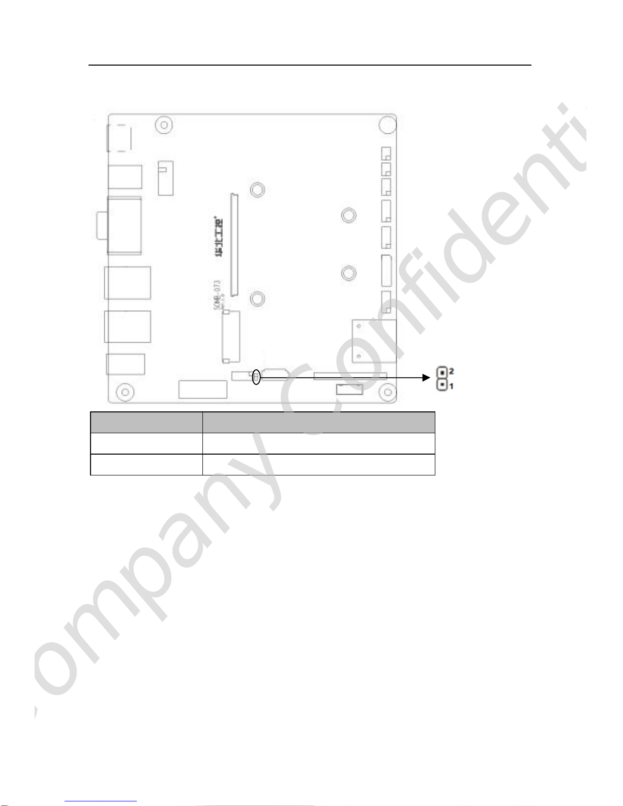
2.2.1Start Upon Power-onHardwareSwitch JAT)......................................................4
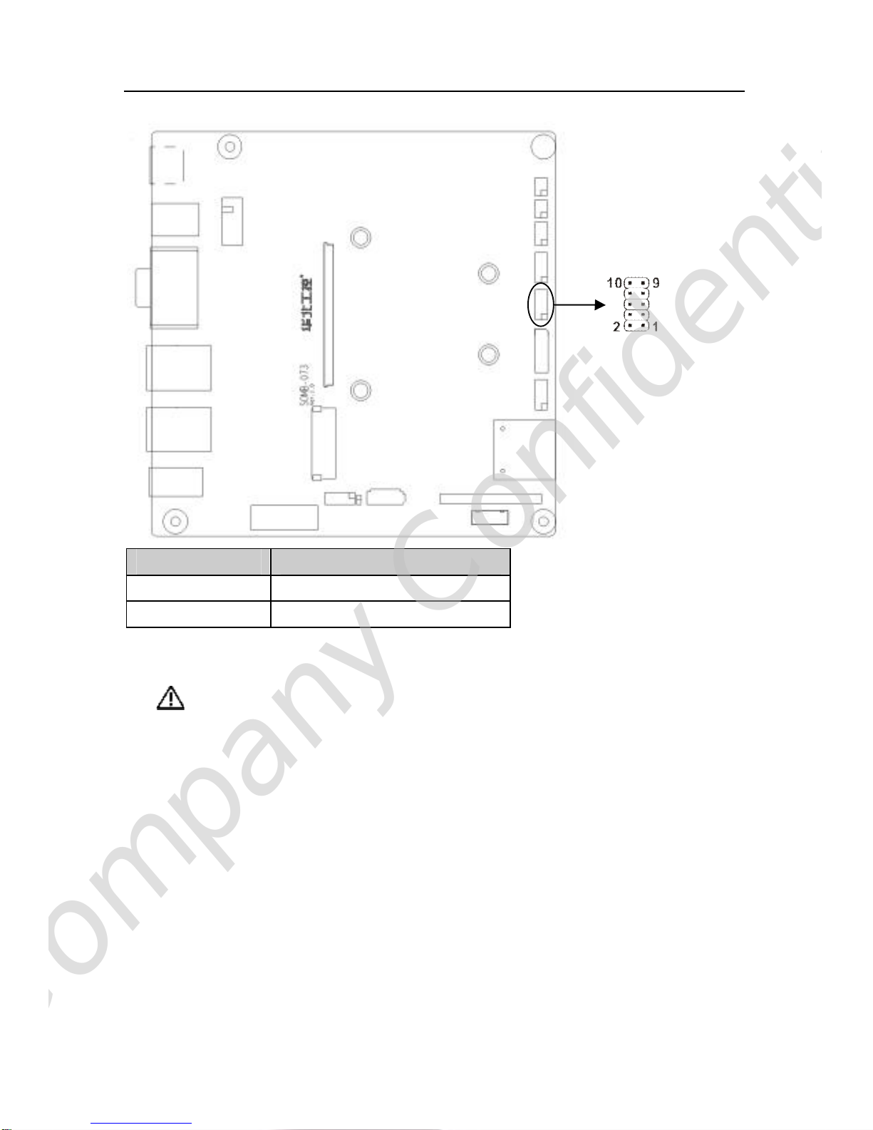
2.2.2COM2JumperSetting J5, J6, J7)....................................................................4
2.2.3LVDSVoltageJumperSetting JLVDS).............................................................5
2.3InterfaceSpecification......................................................................................................6
2.3.1SATAInterfaces SATA1, SATA2, JSATA).........................................................6
2.3.2Serial Ports COM1,COM2)...............................................................................8
2.3.3DisplayInterface VGA, LVDS)........................................................................10
2.3.4LVDSBacklightControl JLVDS).....................................................................11
2.3.5USB Ports USB, USB45)................................................................................12
2.3.6NetworkInterface LAN)...................................................................................13
2.3.7KeyboardandMouseConnector PS2)..........................................................13
2.3.8AudioInterface(AUDIO)......................................................................................15
2.3.9GPIOConnector JGP)....................................................................................15
2.3.10PowerInterface DC_JACK)............................................................................17
2.3.11FrontPanel Connector JFP).........................................................................17
2.3.12SDCardSocket..................................................................................................19
2.3.13PCIE_X1Port.....................................................................................................19
2.3.14MiniPCIEPort MINI_PCIE).............................................................................19
CompanyConfidential

Chapter1.Product
Introduction
CompanyConfidential

SOMB-073 QSEVENCarrierBoard
1
Chapter1ProductIntroduction
1.1Product Specification
StandardStructure
QSEVENCarrierBoard
ConformstoMINI-ITXspecification withadimensionof170mm×170mm
Storage
2*standardSATAinterfaces
1*SDIOport compatiblewithMMC
DisplayInterface
1*standardDB15VGAportwithresolutionupto1280×1024@85Hz
1*2×10Pinsupporting24/18bit LVDSinterfacewithresolution up to1280×768@60Hz
I/0
Adopt WinbondW83627DHG-PI/Ochip
2*COMwithCOM1supportingRS232andCOM2supportingRS-232/422/485
1set standarddoublelayerPS2KB&MSconnector
1*2×5Pin,8BitsGPIOport
USB
6*USB2.0
2group doublelayerstandardUSBport
1*2x5Pininterface,abletoconverted to2*standardUSBports
LAN
AdoptRTL8211CL+RTL8111Dchip
2*standardRJ45ports
AudioInterface
AdoptALC887chip
Standardtri-layerAUDIOinterfacesupportingMIC-IN, LINE-IN,LINE-OUT
CompanyConfidential

SOMB-073 QSEVENCarrierBoard
2
Expansions
1*PCIE_×1
1*MINI-PCIE
PowerSupply
+12VSinglePowerSupply
Environment
OperatingTemperature:
-40 -80 Industrial grade)
0-60 commercial grade)
StorageTemperature:-40 -85
OperatingHumidity: 0-95%relativehumidity,no-condensing
CompanyConfidential

Chapter2.In
terface
Instruction
CompanyConfidential

SOMB-073 QSEVENCarrierBoard
3
Chapter2Interface Instruction
2.1InterfaceLocationand Dimension Diagram
The followingpictureistheinterfaceindexforSOMB-073. Whenyouinstall thisdevice,please
consult itandreadthefollowinginstruction.Duringtheinstallation,pleasecareforsome
devices, astheimproperinstallation ofsomecomponentswill leadtosystemfailure.
Remark: Duringinstallation, inordertoprotectthepartsofmotherboard,pleasewearyour
antistaticgloves.
2.2JumperSetting
Pleaseconfig thejumpersaccordinglybeforeinstallinghardwaredevices
Note: HowtoidentifyjumperandPIN1ofinterface
Pleaseobservethewordmarkofplugsocket, it willuse“1”orboldlineortriangularsymbols;
andpleaselookatthebackofPCB,eachofinterfaceweld spothasasquarpoint, thatisPIN1;
The pin1of alljumperswillhaveawhitearrow.
CompanyConfidential

SOMB-073 QSEVENCarrierBoard
4
2.2.1 StartUponPower-onHardwareSwitch JAT)
JAT PowerMode
Close Self-start upon poweron
Open Non self-start upon poweron
2.2.2COM2JumperSetting J5,J6,J7)
J5,J6,J7areused toconfigthetransmissionmodeofCOM2. COM2supports
RS232/RS422/RS485.Userscan config thisportbased on theactualneeds.
CompanyConfidential

SOMB-073 QSEVENCarrierBoard
5
COM2RS232 COM2RS422 COM2RS485
J5 3-54-6 J5 1-32-4 J5 1-32-4
J6 3-54-6 J6 1-32-4 J6 1-32-4
J7 1-2 J7 3-4 J7 5-67-8
2.2.3LVDSVoltageJumperSetting JLVDS)
Beforeusintthechosen LVDS,pleasemakeclearofitsrated voltageforoperating.Thenyou
can choosethevoltageforchosen LVDSviaJLVDSjumpersetting.
J5 J6
J7
CompanyConfidential

SOMB-073 QSEVENCarrierBoard
6
Pin SignalName
2-4 3.3V
4-6 5V
2.3InterfaceSpecification
Beforeconnecting externalinterface, pleasereadthismanualcarefully,itwill
protectmotherboard fromdamage
2.3.1SATAInterface SATA1,SATA2,JSATA)
2*standardSATAinterfaces.SATA1isthe7+15Pininterface. JSATAisthepowersupply
connectorforSATA2.
CompanyConfidential

SOMB-073 QSEVENCarrierBoard
7
SATA1:
Pin SignalName Pin SignalName
1 GND P4 GND
2 SATA_TX_P0 P5 GND
3 SATA_TX_N0 P6 GND
4 GND P7 VCC
5 SATA_RX_N0 P8 VCC
6 SATA_RX_P0 P9 VCC
7 GND P10 GND
8 NC P11 GND
9 GND P12 GND
10 NC P13 +12V
P1 VCC3 P14 +12V
P2 VCC3 P15 +12V
P3 VCC3
SATA2:
Pin SignalName
1 GND
CompanyConfidential

SOMB-073 QSEVENCarrierBoard
8
2 TX+
3 TX-
4 GND
5 RX-
6 RX+
7 GND
JSATA:
Pin SignalName
1 +12V
2 GND
3 VCC
4 GND
5 VCC3
2.3.2SerialPorts COM1, COM2)
Boardprovides2*serial ports. COM1adoptsthestandardDB9interface. COM2adopts
2×5Pininterface.TheseserialportsneedtobeconvertedtoDB9portviaaconvertcable,so
astoconnect external devices. BothCOM1andCOM2support RS232 transmissionmode
andCOM2alsosupportsRS422/485.Usersareabletochoosethetransmission modefor
COM2viajumpersetting. PleaserefertoChapter2-2.2 “COM2setting”.
CompanyConfidential

SOMB-073 QSEVENCarrierBoard
9
COM1:
Pin SignalName
1 DCD
2 RXD
3 TXD
4 DTR
5 GND
6 DSR
7 RTS
8 CTS
9 RI
COM2:
SignalName Pin SignalName
DCD 1 2 DSR
RX 3 4 RTS
TX 5 6 CTS
DTR 7 8 RI
GND 9 10 GND
CompanyConfidential

SOMB-073 QSEVENCarrierBoard
10
2.3.3DisplayInterface(VGA,LVDS)
OnboardprovidesonestandardVGAinterfaceandone20PinLVDSinterface supporting
18/24biwithresolution upto1280×768@60Hz)。
VGA:
Pin SignalName Pin SignalName Pin SignalName
1 RED 6 GND 11 NC
2 GREEN 7 GND 12 SDA
3 BLUE 8 GND 13 HSYNC
4 NC 9 +5V 14 VSYNC
5 GND 10 GND 15 5VDDCK
LVDS:
SignalName Pin SignalName
VCC 1 2 VCC
GND 3 4 GND
LVDS_D0- 5 6 DDC_DATA
CompanyConfidential

SOMB-073 QSEVENCarrierBoard
11
LVDS_D0+ 7 8 DDC_CLK
GND 9 10 GND
LVDS_D1- 11 12 LVDS_CLK-
LVDS_D1+ 13 14 LVDS_CLK+
GND 15 16 GND
LVDS_D2- 17 18 LVDS_D3-/ NC
LVDS_D2+ 19 20 LVDS_D3+ /NC
2.3.4LVDSBacklightControl JLVDS)
JLVDSisused toadjustthebrightness ofLVDSbacklight panel.
JLVDS:
Pin SignalName
1 +12V
3 L-BKLT_EN
5 GND
7 L-BKLTCLT
9 VCC
CompanyConfidential

SOMB-073 QSEVENCarrierBoard
12
2.3.5USBPorts USB, USB45)
Boardprovides6USB ports,including2groupdouble-layerstandardUSB portsandone
2×5PinUSBport.
USB:
Pin SignalName
1 +5V
2 USB DATA-
3 USB DATA+
4 GND
USB45:
SignalName Pin SignalName
VCC 1 2 GND
USBD4+ 3 4 GND
USBD4- 5 6 USBD5+
GND 7 8 USBD5-
GND 9 10 VCC
CompanyConfidential

SOMB-073 QSEVENCarrierBoard
13
2.3.6NetworkInterface LAN)
Boardprovides2*RJ45.Bothsidesof RJ-45Ethernet port willhaveoneLEDindicator.The
yellowon indicatesthestatusof datatransmission, whilethegreenoneindicatesnetwork
connection status.
RJ45PORTLEDStatus
LILED(GREEN)Function ACTLED(YELLOW) Function
ON EffectiveON Datatransmitting
OFF Ineffective/closeOFF Nodata
2.3.7Keyboardand MouseConnector PS2)
Boardprovidesonedouble-layerPS2KB/MSconnector. Userscanplugthekeyboardand
mouseintocorrespondingconnectors GREENforthemouseconnector, PURPLEforthe
keyboardconnector).
CompanyConfidential

SOMB-073 QSEVENCarrierBoard
14
MS:
Pin SignalName
1 +5V
2 GND
3 NC
4 MS_DATA
5 MS_CLK
6 NC
KB:
Pin SignalName
1 +5V
2 GND
3 NC
4 KB_DATA
5 KB_CLK
6 NC
CompanyConfidential

SOMB-073 QSEVENCarrierBoard
15
2.3.8AudioInterface(AUDIO)
Boardprovidesonegrouptriple-layerAUDIOinterface, supportingLINE-OUT GREEN),
LINE-IN BLUE)andMIC-IN PINK).
2.3.9GPIOConnector JGP)
It providesI/Oexpansions. Whenthemicro-controllerorthechipsetdoesn’thaveenough
I/O,orsystemneedstoadoptremoteserial communicationandcontrol, GPIOcan help
provideextended control andmonitoringfunctions.
CompanyConfidential

SOMB-073 QSEVENCarrierBoard
16
JGP:
SignalName Pin SignalName
GP30 1 2 VCC
GP31 3 4 GP34
GP32 5 6 GP35
GP33 7 8 GP36
GND 9 10 GP37
CompanyConfidential
Table of contents
Other Norco Motherboard manuals

Norco
Norco SOM-6670 User manual

Norco
Norco MITX-6973 User manual

Norco
Norco MITX-6922 User manual

Norco
Norco SOM-6503 User manual

Norco
Norco MITX-6946 User manual

Norco
Norco EMB-7540 User manual

Norco
Norco EMB-7536 User manual

Norco
Norco BPC-7936 User manual

Norco
Norco ATX-6991 User manual

Norco
Norco EMB-7541 User manual

Norco
Norco BPC-7934 User manual

Norco
Norco BPC-7971 User manual

Norco
Norco MITX-6110 User manual

Norco
Norco EMB-2510 User manual

Norco
Norco EMB-3682 User manual

Norco
Norco MATX-6959 User manual

Norco
Norco MITX-6910 User manual

Norco
Norco MITX-6922 User manual

Norco
Norco MITX-6854 User manual

Norco
Norco EMB-4850 User manual