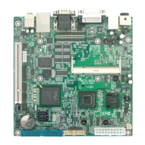
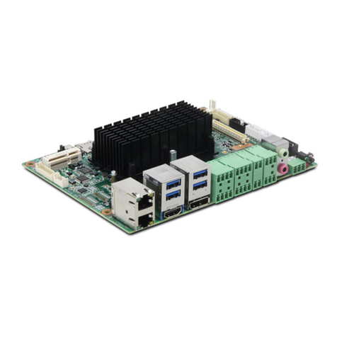
Norco MITX-6891 User manual

Contents
Chapter1 General Information..................................................................................... 1
1.1 Introduction ................................................................................................................. 1
1.2 Specifications..............................................................................................................1
Chapter2 Installation Instructions.............................................................................. 4
2.1 Connector Locations and Dimensions ........................................................................ 4
2.2 Installation Steps......................................................................................................... 5
2.3 2.3 Installing a DIMM .................................................................................................. 6
2.4 Central Processing Unit (CPU) ................................................................................... 6
2.5 Setting Jumpers........................................................................................................ 12
2.5.1 Clear CMOS (JCC) ................................................................................................ 12
2.5.2 BIOS-protect Jumper (JAV) ................................................................................... 12
2.5.3 DVI Connector Jumper(J1,J2,J3,J4)......................................................... 14
2.6 External Connector ................................................................................................... 15
2.6.1 SATA Connector(SATA1,SATA2).................................................................... 15
2.6.2 Serial port(COM)............................................................................................... 16
2.6.3 Display Connector(DVIB,DVIC)...................................................................... 16
2.6.4 USB&Ethernet ports(USB,LAN_USB.USB1-3)................................................. 19
2.6.5 LAN LED(LAN_LED)......................................................................................... 21
2.6.6 Keyboard and Mouse port(PS/2)...................................................................... 21
2.6.7 IRDA interface(IRDA)........................................................................................ 23
2.6.8 GPIO(GPIO)...................................................................................................... 24
2.6.9 Power Supply Connectors (ATX,PWR).................................................................. 25
2.6.10 Fan Socket(CPUFAN1,CPUFAN2,SYS_FAN)................................................ 26
2.6.11 Audio Port(AUDIO,J5) .......................................................................................... 27
2.6.12 Front Panel connector(FRONT)...................................................................... 28
2.6.13 RAM Socket(DIMM 1,DIMM 2ⅢⅢ)..................................................................... 30
2.6.14 Mini PCI-E Slot(Mini PCI-E)............................................................................ 31
Chapter3 BIOS Setup..................................................................................................... 32


3.1 Standard CMOS Setup ............................................................................................. 33
3.2 Advanced BIOS Features ......................................................................................... 36
3.2.1 CPU Feature.......................................................................................................... 36
3.2.2 Removable Device Priority .................................................................................... 38
3.2.3 Hard Disk Boot Priority .......................................................................................... 38
3.2.4 CD-ROM Boot Priority ........................................................................................... 39
3.3 Advanced Chipset Features...................................................................................... 42
3.4.1 OnChip IDE Device................................................................................................ 45
3.4.2 Super IO Device .................................................................................................... 47
3.4.3 USB Device Setting ............................................................................................... 48
3.5 Power Management Setup ....................................................................................... 49
3.6 PnP/PCI Configurations............................................................................................ 53
3.7 PC Health Status ...................................................................................................... 55
3.8 Load Fail-Safe Defaults ............................................................................................ 56
3.9 Load Optimized Defaults .......................................................................................... 57
3.10 Set Supervisor Password ....................................................................................... 57
3.11 Set User Password ................................................................................................. 58
3.12 Save&Exit Setup..................................................................................................... 58
3.13 Exit Without Saving................................................................................................. 59
Appendix......................................................................................................................... 60
Appendix 1: Driver Installation ........................................................................................ 60
Appendix 2:Watchdog programmer guide.................................................................... 61
Appendix3:GPIO Instruction......................................................................................... 63
Appendix 4: Glossary...................................................................................................... 64

Packing List
Thank you very much for choosing our products. Please check your package
completely as the following item checklist first, if you find any components lost or
damaged, please contact your retailer.
■MITX-6891 motherboard
■User’s Manual
■Drive Disk
■SATA Data Cable
■Serial port converts cable
■Jumpers
1pcs
1pcs
1pcs
2pcs
1pcs
4pcs

Chapter 1
General Information

MITX-6891 Mini-ITX Motherboard Based on Intel G45 Chipset
1
Chapter1 General Information
1.1 Introduction
MITX-6891 is High Performance Mini-ITX motherboard based on Intel G45+ICH10
chipset ,supports Intel® Virtualization Technology LGA775 Intel® Core™2 Duo、Intel® Core™2
Quad and Intel® Celeron®440 (Conroe-L) processor. .MITX-6891 has two 240-pin DDRⅢ
800/1066MHz DIMM socket support system memory max. upto 2GB. Northbridge integrated
Intel GMA X4500, 4xDVI video output (3x DVI-D, 1x DVI-I). Networks using Marvell PCIe
Gigabit PHY 88E8075 chip support WOL, PXE, DASH technology to provide an RJ-45 Gigabit
LAN PCIE_1X to support 10/100/1000 Mbps self-adaptive ,Provide two SATA , sevenⅡ
USB2.0, one COM etc.
MITX-6891 is an integrated powerful computing platform with standard digital input/out
ports、Mini PCI-E slot、IrDA,Watchdog Timer. It is specially suitable for POS、kiosk、ATM and
Rail Transportation applications.
1.2 Specifications
Configuration Standard
●Mini-ITX Standard motherboard
Dimensions
●170mm X 170mm(L×W)
Processor
●Supports the Intel® Core™2 Duo and Intel® Core™2 Quad processors with Intel®
Virtualization Technology, and Intel® Celeron®440 (Conroe-L) processor
●FSB:800/1066/1333MHz
Chipset
●North Bridge:Intel®G45 Express chips
●South Bridge:Intel®ICH10
●The DMI interface connected the South and North Bridge, and support upto 2GB/s data
transmission speed. This interface has increased the data transmission speed of the system.

MITX-6891 Mini-ITX Motherboard Based on Intel G45 Chipset
2
Display
●Chipshet:Intel®G45 integration Intel® Graphics Media Accelerator X4500HD
●DVI:Onboard DVI Display Controlle(G45 integration),3x DVI-D output,1x DVI-I output
(DVI-I Signal can be convert to VGA signal).Support resolution up to 2560x1600
RAM
●MITX-6891 has two 240 Pin DIMM DDR 800/1066MHz socket support system memory max.Ⅲ
upto 4GB.
●No Support ECC
●Supporting DDR 800MHz, its bandwidth can reach up to 12.8GB/s in dual channel modelⅢ
●Supporting DDR 1066ⅢMHz, its bandwidth can reach up to 17GB/s in dual channel model
Storage
●2x Serial ATAⅡPorts, The transfer speed is up to 300MB/s
LAN
●Chipset:Marvell PCIe Gigabit PHY 88E8075,Supports WOL,PXE,DASH technology
●1x GbE PCIE_1X NIC,Support 10/100/1000 Mbps adapting
●1x RJ45 port
Audio
●Chipset: ALC888
●Audio Controller: Supports AC97 Audio stereo sound
●Audio Interface:Speak out,MIC-IN
USB Port
●7x USB2.0 ports,The transfer speed is up to 480Mbps
●Backpanel 4x USB ports
●3 group 1x5Header ports,can convert to 3x stanard USB ports
Expandsion slot
●1x Mini PCI-E slot

MITX-6891 Mini-ITX Motherboard Based on Intel G45 Chipset
3
I/0 Functions
●IO Chipset: Winbond W83627DHG
●Provide One 2x5Pin serial port,support RS232
●Norma PS/2 keyboard and mouse port
●1x IrDA port
●Programmable input/output interfaces,2x6Pin,6input/6output
Power Supply
●+12V plug + Standard ATX PowerSupply
Watchdog
●Support H/W reset function
BIOS
●8MB SPI Flash BIOS
●Support ACPI Power manage
Environmental
●Operate Temp:0-60℃
●Storage Temp.:-40-85℃
●Operating Humidity::5%-95%

Chapter 2
Installation Instructions

MITX-6891 Mini-ITX Motherboard Based on Intel G45 Chipset
4
Chapter2 Installation Instructions
2.1 Connector Locations and Dimensions
The following picture is interface index for MITX-6891, when you install your devices,
please consult it and read the following guide. During installation please care: for some devices,
if incorrectly install, it will not work normally.
Notice:During installation, in order to protect the part of board, please put on antistatic gloves。
MITX-6891 Connectors Locations

MITX-6891 Mini-ITX Motherboard Based on Intel G45 Chipset
5
MITX-6891 Dimensions
2.2 Installation Steps
Please refer to the following steps to install your computer:
1. Adjust all Jumpers on the MITX-6891 per this manual.
2. Installing System memory
3:Installing CPU and CPUFAN
4. Connect all of the signal line, cable, panel-control circuitry and power supply
5. Finish BIOS setup
Key components of this motherboard are Integrated circuit, and these components
will be easily damaged by electrostatic influence. So, before installing motherboard, you should
always follow the following precautions:

MITX-6891 Mini-ITX Motherboard Based on Intel G45 Chipset
6
1. Disconnect your Computer from the power supply before handling it.
2. Hold side by the edges; don't touch any component or pins on the board
3. Use a grounded wrist strap while getting in touch with integrated circuit component (like as
CPU, RAM).
4. Place components on a grounded antistatic bag that came with the Single Board Computer,
when these components are separated from the system.
2.3 2.3 Installing a DIMM
CAUTION: Unplug the power supply before adding or removing DIMMs or other system
components. Failure to do so can cause severe damage to both the motherboard and the
components.
To install a DIMM:
1. Unlock a DIMM socket by pressing the retaining clips outward.
2. Align a DIMM on the socket such that the notch on the DIMM matches the break on the
socket.
3. Firmly insert the DIMM into the socket until the retaining clips snap back in place and the
DIMM is properly seated.
IMPORTANT:
• A DDRⅢDIMM is keyed with a notch so that it fits in only one direction. Do not force a DIMM
into a socket to avoid damaging the DIMM.
• The DDRⅢDIMM sockets do not support DDR/DDRⅡDIMMs. Do not install DDR/DDRⅡ
DIMMs to the DDRⅢDIMM sockets.
2.4 Central Processing Unit (CPU)
The motherboard comes with a surface mount LGA775 socket designed for the
Intel processors.
NOTE:
1:Make sure that all power cables are unplugged before installing the CPU.
2: Connect the chassis fan cable to the CHA_FAN1 connector to ensure system stability.
3:Ensure this motherboard support the CPU you choose, if the direction you inserted was
wrong, CPU may be damaged. After system boot, BIOS will examine CPU type and frequency
automatically, BIOS setting won’t allow you change the CPU frequency, in order to make

MITX-6891 Mini-ITX Motherboard Based on Intel G45 Chipset
7
system work steadily, please set your CPU exterior frequency by its specification, and we don’t
suggest you over clock your CPU. At present most Intel ® CPU frequency multiplication have
been set when them leave factory, can not be changed.
2.4.1 Installing the CPU
To install a CPU:
1:Locate the CPU socket on the motherboard
2:Press the load lever with your thumb (A), then move it to the left (B) until it is released from
the retention tab.
NOTE: To prevent damage to the socket pins, do not remove the PnP cap unless you are
installing a CPU.
3:Lift the load lever in the direction of the arrow to a 135° angle.

MITX-6891 Mini-ITX Motherboard Based on Intel G45 Chipset
8
4:Lift the load plate with your thumb and forefinger to a 100º angle (A), then push the PnP cap
from the load plate window to remove (B).
5:Position the CPU over the socket, making sure that the gold triangle is on the bottom‑left
corner of the socket then fit the socket alignment key into the CPU notch.
NOTE:The CPU fits in only one correct orientation. DO NOT force the CPU into the socket to
prevent bending the connectors on the socket and damaging the CPU!
6:Close the load plate (A), then push the load lever (B) until it snaps into the retention tab.

MITX-6891 Mini-ITX Motherboard Based on Intel G45 Chipset
9
2.4.2 Installing the CPU heatsink and fan
To install the CPU heatsink and fan::
1:Place the heatsink on top of the installed CPU, making sure that the four fasteners match the
holes on the motherboard.
2:Push down two fasteners at a time in a diagonal sequence to secure the heatsink and fan
assembly in place.
3:Connect the CPU fan cable to the connector on the motherboard labeled CPU_FAN.Do not
forgets to connect the CPU fan connector! Hardware monitoring errors can occur if you fail to
plug this connector.
NOTE:Before fixing, daub coolant on the surface of the heat sink connect CPU first to swell the
cooling function, check CPU work on or not regularity, to insure the CPU in good ventilate

MITX-6891 Mini-ITX Motherboard Based on Intel G45 Chipset
10
situation.
2.3.3 Uninstalling the CPU heatsink and fan
To uninstall the CPU heatsink and fan:
1:Disconnect the CPU fan cable from the connector on the motherboard.
2:Rotate each fastener counterclockwise.
3:Pull up two fasteners at a time in a diagonal sequence to disengage the heatsink and fan
assembly from the motherboard.
4:Carefully remove the heatsink and fan assembly from the motherboard.

MITX-6891 Mini-ITX Motherboard Based on Intel G45 Chipset
11
5:Rotate each fastener clockwise to ensure correct orientation when reinstalling.
The narrow end of the groove should point
outward after resetting. (The photo shows the
groove shaded for emphasis.).

MITX-6891 Mini-ITX Motherboard Based on Intel G45 Chipset
12
2.5 Setting Jumpers
Jumpers are located on the motherboard, they represent clear CMOS jumper JCC etc.
pin1 for all jumpers are located on the side with a thick white arrow refer to the motherboard’s
silkscreen , jumpers with three pins will be shown as 1-2 to represent pin1&pin2 connected and
2-3 to represent pin2&pin3 connected.
2.5.1 Clear CMOS (JCC)
This jumper is used to erase CMOS data and reset system BIOS information.The
procedure for clearing CMOS is:
1. Turn off the system.
2. Set JCC closed for just a few seconds.
3. Turn on the system. The BIOS is now reset to its default setting
4. Save&exit setup。
setting JCC
Close Clear CMOS(BIOS renew to initialization)
Open Nomal status(default)
Do not clear CMOS when power switch on, or it harm to the motherboard.
2.5.2 BIOS-protect Jumper (JAV)

MITX-6891 Mini-ITX Motherboard Based on Intel G45 Chipset
13
The BIOS of the CPU card is contained in the Flash ROM. If the jumper JAV1 is set as
dosed, you will be unable to flash the BIOS. However in this status, the system BIOS is
protected from being attacked by serious virus such CIH virus.
Setting JAV
Open Enable to flash BIOS
Close Disable to flash BIOS(default)

MITX-6891 Mini-ITX Motherboard Based on Intel G45 Chipset
14
2.5.3 DVI Connector Jumper(J1,J2,J3,J4)
The motherboard provides 3x DVI-D output and 1x DVI-I output, J1, J2 to set DVIC, J3, J4
to set DVIB. When the J1, J2 is set to 1-2.When the J1, J2 is set to 1-2, the bridge chip only
DVIC-1 signal, if connected to a display, please take in the DVIC-1.When the J1, J2 is set to 2-3,
the bridge chip only DVIC-2 signal, if connected to a display, please take in the DVIC-2.J3, J4
set by reference to J1, J2.
J1,J2:
J1 J2 Port Select
1-2 1-2 DVIC-1
1-2 2-3 DVIC-2
J3,J4:
J3 J4 Port Select
1-2 1-2 DVIB-1
1-2 2-3 DVIB-2
Remarks:J1 and J2,J3 and J4 to simultaneously setup.

MITX-6891 Mini-ITX Motherboard Based on Intel G45 Chipset
15
2.6 External Connector
Please carefully read this manual when connecting external connector, so as to avoid
damage to the motherboard!
2.6.1 SATA Connector(SATA1,SATA2)
The board provide 2 Serial ATAⅡPorts, The transfer speed is up to 300MB/s.
SATA1,SATA2:
Pin Pin Name
1 GND
2 SATA_TXP
3 SATA_TXN
4 GND
5 SATA_RXN
6 SATA_RXP
7 GND
Table of contents
Other Norco Motherboard manuals

Norco
Norco MITX-6854 User manual

Norco
Norco ATX-6991 User manual

Norco
Norco BPC-7971 User manual

Norco
Norco SOM-6503 User manual

Norco
Norco EMB-7541 User manual

Norco
Norco SOM-6670 User manual

Norco
Norco EMB-7540 User manual

Norco
Norco MITX-6922 User manual

Norco
Norco FWMB-7550 User manual

Norco
Norco BPC-7936 User manual

Norco
Norco EMB-3682 User manual

Norco
Norco POS-7893 User manual

Norco
Norco MITX-6934 User manual

Norco
Norco EMB-2510 User manual

Norco
Norco MITX-6910 User manual

Norco
Norco EMB-4850 User manual

Norco
Norco MITX-6946 User manual

Norco
Norco MATX-6959 User manual

Norco
Norco MITX-6854 User manual

Norco
Norco MITX-6922 User manual