Instalação
Instalación
Installation
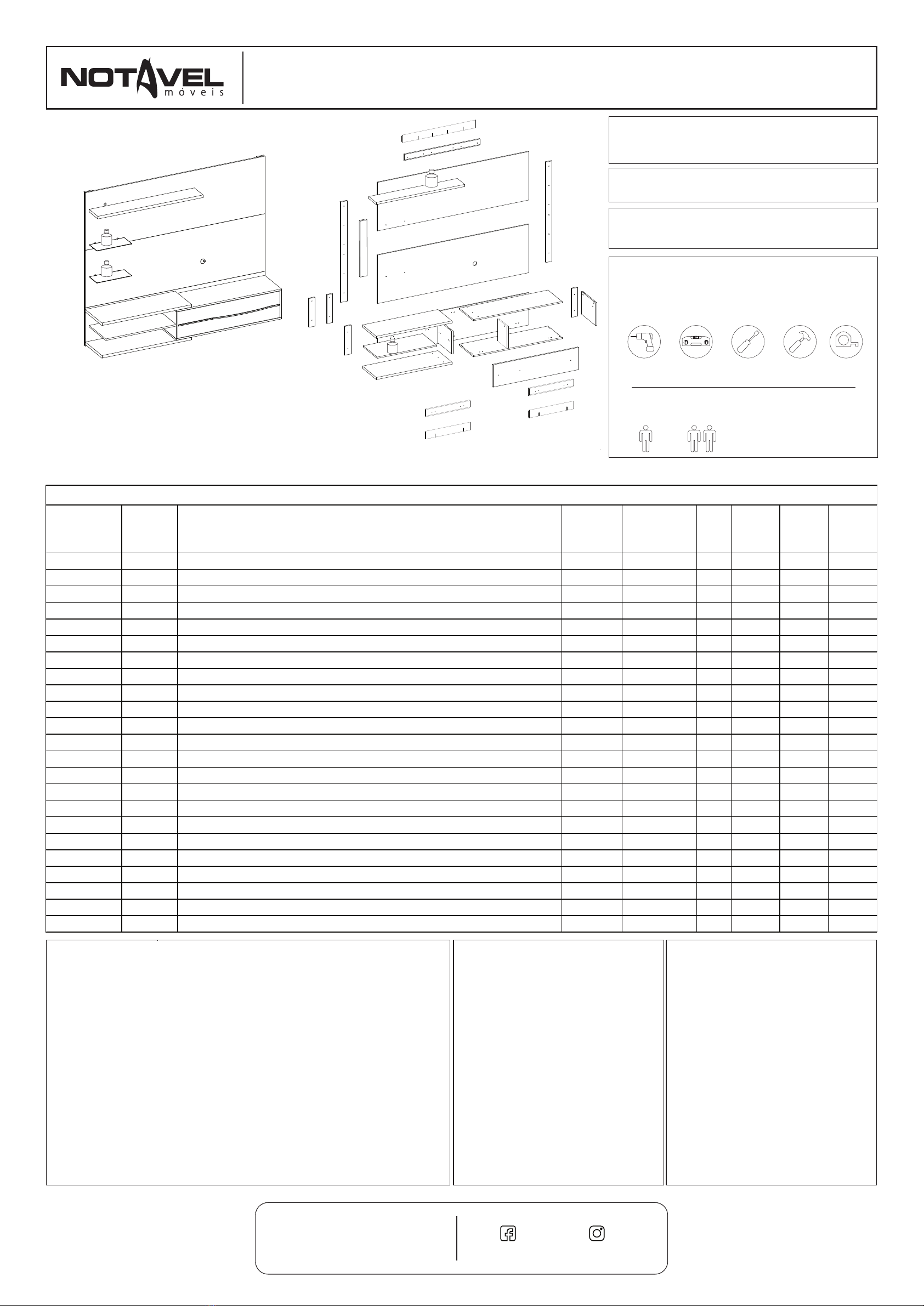
ESQUEMA DE MONTAGEM
INSTRUCCIONES DE MONTAJE
ASSEMBLY INSTRUCTIONS
01. A marcação do número de lote e código da peça que aparece nas fitas é facilmente removida com
borracha escolar ou com pano e álcool.
01. La marca del número de lote y el código de pieza que aparece en las cintas se quita fácilmente con
goma escolar o con paño y alcohol.
01. The marking of the lot number and part code that appears on the tapes is easily removed with school
rubber or with cloth and alcohol.
02. Para reclamações, ter à mão a etiqueta do produto com número do lote e data da fabricação.
02. Para cualquiera que sea la reclamación hay que tener siempre a mano la etiqueta del producto con el
número del lote y la fecha de fabricación.
02. For complaints always have the product label with the batch number and manufacturing date at hand.
03. Sr. Montador, favor conferir as peças antes da montagem, pois só efetuamos a troca do produto antes de
ser montado.
03. Señor ensamblador, favor conferir las piezas antes del montaje, pues sólo cambiamos los productos antes
de ensamblados.
03. Mr. Assembler, please check parts before assembling. We only replace products before put together.
COD: NT1115
PAINEL NT 1115
PANEL NT 1115
PAINEL NT 1115
DIMENSÕES TOTAIS | DIMENSIONES TOTALES |
: 1505x1800x360mm OVERALL DIMENSIONS
VOLUME | VOLUMEN | VOLUME: 02
CAPACIDADE TV | CAPACIDAD TV | TV SIZE: 60''
DESTORNILLADOR
ELETRIC SCREW
DRIVER
MARTILLO
HAMMER
DESTORNILLADOR
Y DE CRUCETA
PHILLIPS
SCREWDRIVER
CINTA MÉTRICA
MEASURING
TAPE
NIVEL
NIVEL
5M
FERRAMENTAS PARA MONTAGEM E INSTALAÇÃO
HERRAMIENTAS PARA ENSAMBLAJE E INSTALACIÓN
TOOLS FOR ASSEMBLY AND INSTALLATION
Ferramentas não fornecidas | Herramientas no proporcionadas | Tools not supplied
Montagem
Ensamblaje
Assembly
ATENÇÃO: Sugerimos montar os produtos sobre
a embalagem para evitar arranhões nas peças.
PRECAUCIÓN: Sugerimos ensamblar los
productos sobre el embalaje para evitar
rayaduras en las partes.
ATTENTION: We suggest assembling the
products on the packaging to avoid scratches on
the parts.
•A TV deverá ser fixada no Painel. Não
utilize a TV apenas apoiada sobre nicho.
•La TELE deberá ser fijada en el panel. No
utilice la TELE apoyada sólo sobre el nicho.
•The TV should be attached to the Panel. Do
not use the niche-only TV.
PÁGINA | PAGINA | PAGE: 01
PARAFUSADEIRA NÍVEL CHAVE PHILIPS
E FENDA MARTELO TRENA
0,5kg
0,5kg
1
3
16
8
13
11
12
2
4
6
6
7
10
10
15
15
14
14
18
3kg
2kg
9
21
9
21
19
20
22
ACOMPANHE A NOTÁVEL MÓVEIS NAS REDES SOCIAIS.
SIGA EL NOTAVEL MOVEIS EN LAS REDES SOCIALES.
FOLLOW THE NOTAVEL MOVEIS ON THE SOCIAL NETWORKS @NOTAVELMOVEIS
/NOTAVELMOVEIS
CÓD PRODUTO
CÓD PRODUCTO
CODE
DESCRIÇÃO
DESCRIPCIÓN
DESCRIPTION
MATERIAL
COD PEÇA
COD PIEZA
PART CODE
NT1115 1 LATERAL DIREITA | LATERAL DERECHA | RIGHT SIDE MDP 43319-01 1 265 330 15
NT1115 2 BASE PORTA | BASE PUERTA | DOOR BASE MDP 43320-02 1 1055 332 15
NT1115 3 LATERAL ESQUERDA | LATERAL IZQUIERDA | LEFT SIDE MDP 43322-03 1 265 330 15
NT1115 4 TAMPO PORTA | CUBIERTA PUERTA | DOOR TOP MDP 43321-04 1 1055 332 15
NT1115 6 BASE ESQUERDA | BASE IZQUIERDA | LEFT BASE MDP 43324-06 2 900 333 25
NT1115 7 PRATELEIRA INFERIOR | REPISA INFERIOR | LOWER SHELF MDP 43325-07 1 706 296 15
NT1115 8 PAINEL INFERIOR | PANEL INFERIOR | LOWER PANNEL MDP 43326-08 1 1800 375 15
NT1115 9 SUPORTE 45º INFERIOR | SOPORTE 45º INFERIOR | LOWER 45º SUPPORT MDP 43327-09 2 450 78 15
NT1115 10 SUPORTE INFERIOR | SOPORTE INFERIOR | LOWER SUPPORT MDP 43329-10 2 335 70 15
NT1115 11 PAINEL SUPERIOR | PANEL SUPERIOR | UPPER PANEL MDP 43330-11 1 1800 565 15
NT1115 12 PRATELEIRA SUPERIOR | REPISA SUPERIOR | UPPER SHELF MDP 43331-12 1 1055 175 25
NT1115 13 PAINEL CENTRAL | PANEL CENTRAL | CENTER PANEL MDP 43332-13 1 1800 565 15
NT1115 14 SUPORTE SUPERIOR | SOPORTE SUPERIOR | UPPER SUPPORT MDP 43333-14 2 1170 70 15
NT1115 15 SUPORTE CENTRAL | SOPORTE CENTRAL | CENTRAL SUPPORT MDP 43334-15 2 335 75 15
NT1115 16 PORTA DIREITA | PUERTA DERECHA | RIGTH DOOR MDP 43335-16 1 1018 259 15
NT1115 18 SUP. 45º SUPERIOR | SOP. 45º SUPERIOR | UPPER 45º SUPPORT MDP 43398-18 1 900 78 15
NT1115 19 DIVISORIA | DIVISION | DIVISORY MDP 43420-19 1 265 192 15
NT1115 17 KIT ACESSÓRIO | KIT ACCESORIOS | ACCESSORIES SET - 43336-17 1 - - -
NT1115 20 SUPORTE TRAVA | SOPORTE DE BLOQUEO | LOCK SUPPORT MDP 43429-20 1 540 70 12
NT1115 21 SUP. 45º INFERIOR PAREDE | SOPORTE 45º PARED INFERIOR | SUPPORT WALL 45º LOWER MDP 43430-21 2 450 78 15
NT1115 22 SUP. 45º SUPERIOR PAREDE | SOPORTE 45º PARED SUPERIOR | SUPPORT WALL 45º UPPER MDP 43431-22 1 900 78 15
NT1115 PUXADOR DE ALUMÍNIO | MANIJA ALUMINIO | ALUMINIUM HANDLE - 1810 1 1016 - -
NT1115 VIDRO INCOLOR | VIDRIO INCOLORO | COLORLESS GLASS - 1871 2 350 150 8
RELAÇÃO DE PEÇAS | LISTA DE PIEZAS | PARTS LIST
TERMO DE GARANTIA
A presente garantia deverá ser exercida nos prazos aqui indicados,
mediante apresentação deste certificado e da nota fiscal.
Para que o produto esteja assegurado pela garantia conferida neste
documento, o cliente deverá adotar as seguintes orientações e cuidados
quanto à montagem, conservação e limpeza.
MONTAGEM
A montagem deverá ser feita obedecendo as instruções do manual
de montagem que será fornecido com o produto no momento da entrega.
Para o uso adequado e conservação do móvel deve-se evitar maus
tratos, como por exemplo: bater portas e gavetas, arrastar ou riscar o
móvel, umidade ou calor excessivos e exposição ao sol, para evitar
possível alteração na cor original dos móveis.
Não será de responsabilidade da Notável Móveis problemas que
tenham origem na utilização dos produtos de forma inadequada ou
quebra do móvel em função do excesso de peso por colocação de pedras
de granito, mármore e outros.
- O peso suportado por cada prateleira deverá obedecer os valores
indicados na ilustração.
Também não serão de responsabilidade da Notável Móveis,
problemas que tenham origem em:
- Instalações elétricas ou hidráulicas.
- Ações de cupins ou outras pragas.
- Armazenamento e deslocamento do móvel em locais impróprios e
não dedetizados periodicamente.
- Todo e qualquer recorte ou alteração nos móveis.
- Uso de produtos de limpeza ou abrasivos não recomendados.
CONSERVAÇÃO E LIMPEZA
Para maior durabilidade, recomenda-se que a limpeza dos móveis
seja feita da seguinte forma:
Nas partes externas (portas, laterais e frente de gaveta), internas,
vidros e espelhos, a limpeza deverá ser feita com pano limpo e levemente
umedecido em água e sabão neutro. Em seguida, deverá ser passado um
pano limpo e seco.
Em caso de transferência do móvel para local diverso, esta só
poderá ocorrer através de profissional especializado, sendo que para a
movimentação do móvel é necessário que o mesmo seja levantado do
chão. O produto não deve ser arrastado, pois avarias no manuseio e
transporte, não estão contempladas na garantia.
DOCUMENTO DE FIANZA
Esta garantía se ejerce dentro del
periodo en el presente documento, con
la presentación de este certificado y la
factura.
Pa ra que el p rod uct o e sté
garantizado por la garantía dada en este
documento, el cliente debe tomar las
siguientes directrices y precauciones de
instalación, mantenimiento y limpieza.
MONTAJE
El montaje se realizará siguiendo
las instrucciones de ensamblaje que
serán proporcionadas con la entrega del
producto.
Para el uso adecuado y la
conservación del mueble se debe evitar
los malos tratos, tales como: golpear
puertas y cajones, arrastrar o arañar los
muebles, humedad o el calor excesivos y
la exposición al sol para evitar un posible
cambio en el color original de los
muebles.
No será responsabilidad de
Notável Móveis problemas que se
originen en el uso de los productos de
forma inapropiada o ruptura del mueble
en función de exceso de peso mediante
la colocación de piedras de granito,
mármol y otros.
- El peso soportado por cada
estante debe cumplir con los valores
indicados en la ilustración.
Tampoco serán responsabilidad
de Notável Muebles los problemas que
se originan en:
- Instalaciones eléctricas o
hidráulicas.
- Acciones de termitas u otras
plagas.
- Almacenamiento y cambio del
mueble en locales inapropiados y no
fumigados periódicamente.
- Todo y cada corte o cambio en
los muebles.
- Uso de productos de limpieza o
abrasivos no recomendados.
CUIDADO Y LIMPIEZA
Para una mayor durabilidad, se
recomienda que la limpieza de los
muebles sea hecha como sigue:
En las partes externas (puertas,
laterales y frontales de cajón), internas,
vidrios y espejos, la limpieza debe ser
hecha con paño limpio y ligeramente
humedecido con agua y jabón suave. A
continuación, se debe pasar un paño
limpio y seco.
En el caso del traslado del mueble
a otro sitio, esto sólo puede ocurrir a
través de profesionales especializados,
y para el manejo del mueble se requiere
que el mismo sea levantado del piso. El
producto no debe ser arrastrado pues
daños en la manipulación y el transporte
no están cubiertos por la garantía.
WARRANTY TERM
This warranty shall be applied
within the time limits specified herein, by
presentation of this certificate and
invoice.
In order for the product to be
covered by the warranty provided in this
document, the client should follow the
following guidelines and precautions for
assembly, maintenance and cleaning.
ASSEMBLY
Assembly must be carried out
according to the instructions in the
assembly manual which is supplied with
the product at the time of delivery.
For proper use and conservation
of this furniture, mistreatment should be
avoided, such as hitting doors and
drawers, dragging or scratching the
furniture, excessive moisture or heat to
avoid possible changes in its original
color.
Problems from improper use of
the products as breaking of the furniture
due to the excess weight by installation
of granite, marble, and others will not be
the responsibility of Notável Móveis
- The weight withstood by each
shelf/drawer must comply with the
values indicated in illustration.
It will not be responsibility of the
Notável Móveis either problem from:
- E l e c t r i c al o r h y d r a u l i c
installations.
- Actions of termites or other pests.
- Storage and moving of the
furniture in inappropriate places and not
fumigated periodically.
- Any trimming or alteration in the
furniture.
- Use of cleaning agents or
abrasives not recommended.
UPKEEP AND CLEANING
For durability, it is recommended
that the furniture be cleaned this way:
In the outer parts (doors, sides
and drawer front), inside, glass and
mirrors, the cleaning should be done with
a cloth clean and lightly moistened with
mild soap and water. Then a clean, dry
cloth should be used.
In case of transfer of the furniture
to a different place, this can only be done
by specialized professionals, and for the
moving of the furniture it is necessary
that it is lifted off the ground. It should not
be dragged because malfunctions due to
handle and moving are not covered by
the warranty.
PRAZO DE GARANTIA
O prazo de garantia será de noventa (90) dias, conforme prevista no artigo 26 do Código
do Consumidor, a contar da efetiva entrega do produto, desde que observadas as condições
normais de uso e conservação. Essa garantia cobre defeitos de fabricação. A Indústria de
Móveis Notável não se responsabiliza pela garantia estendida adquirida pelos consumidores
junto aos lojistas e seguradoras, a garantia legal da fabricante é de 90 dias. Art. 26, II, CDC.”
A MARCAÇÃO DO NÚMERO DE LOTE E CÓDIGO DA PEÇA QUE APARECE NAS
FITAS É FACILMENTE REMOVIDA COM BORRACHA ESCOLAR OU COM PANO E ÁLCOOL


