Ojmar Nexo NLX1 Guide

NLX1®
LOCK INSTALLATION AND ASSEMBLY
V2.1


NLX1_INDEX OJMAR 1
INDEX
ENGLISH 1
1. NLX1 LOCK INSTALLATION AND ASSEMBLY ............................................................................................................1
1.1. Lock directions .........................................................................................................................................................1
1.2. Assembly instructions..............................................................................................................................................2
1.3. Steps to follow for assembly ...................................................................................................................................5
1.4. Procedure to unmount the lock...............................................................................................................................7
ESPAÑOL 9
1. INSTALACIÓN Y MONTAJE DE LA CERRADURA NLX1 .............................................................................................10
1.1. Orientación de la cerradura...................................................................................................................................10
1.2. Instrucciones de montaje ......................................................................................................................................11
1.3. Pasos a seguir para el montaje.............................................................................................................................14
1.4. Pasos a seguir para el desmontaje.......................................................................................................................16
DEUSTCH 18
1. INSTALLATION UND EINBAU EINES NLX1 SCHLOSSES..........................................................................................20
1.1. Ausrichtung des Schlosses....................................................................................................................................20
1.2. Hinweise zum Einbau.............................................................................................................................................21
1.3. Einbauschritte ........................................................................................................................................................24
1.4. Demontageschritte.................................................................................................................................................26
FRANÇAIS 28
1. INSTALLATION ET MONTAGE DE LA SERRURE NLX1 .............................................................................................30
1.1. Orientation de la serrure .......................................................................................................................................30
1.2. Instructions de montage ........................................................................................................................................31
1.3. Étapes à suivre pour le montage...........................................................................................................................34
1.4. Etapes à suivre pour le démontage.......................................................................................................................36
NLX1_ INSTALLATION ET MONTAGE DE LA SERRURE NLX1 OJMAR 1
NLX1®
LOCK INSTALLATION AND ASSEMBLY
ENGLISH
V2.1


NLX1_LOCK INSTALLATION AND ASSEMBLY OJMAR 1
1. NLX1 LOCK INSTALLATION AND ASSEMBLY
The NLX1 lock can be installed on doors with thicknesses between 9 mm and 20 mm.
The assembly of the lock in the locker door must be correctly carried out to ensure the correct operation of the lock.
The positioning of the holes, the distance of the lock on the locker body and the distance of the lock to the locking device, as
shown in designs 1.2 and 1.3, must be correctly measured to prevent any subsequent problems when locking.
1.1. LOCK DIRECTIONS
Lock installation must be carried out with screws in four drilled holes.
Lock assembly depending on if it is right handed or left handed is as follows.
Design 1.1 - Diagram of right and left locks

NLX1_LOCK INSTALLATION AND ASSEMBLY OJMAR 2
1.2. ASSEMBLY INSTRUCTIONS
The NLX1 lock is attached to the locker door with four screws.
• Recommended screws:
o Conglomerate doors: Pan head wood screw 4.5 x 35 DIN 7996 (depending on the thickness of the door)
o Phenolic or metal doors: Pan head screw M5 x 25 DIN 7985 (depending on the thickness of the door)
• The maximum tightening torque to apply to the tightening of each screw or coach nut will be 150 Ncm.
• The diameter of the central hole should be 23 mm (+1/0 mm). Bevelling the hole on the inner area of the door is
recommended.
During installation, ensure that the lock does not collide with the locker body with the door open (see design 1.2).
The dimensions and location of the anchorage points are shown in the following designs (the dimensions depend on the design
of the locker and the type of striking plate used with the lock:
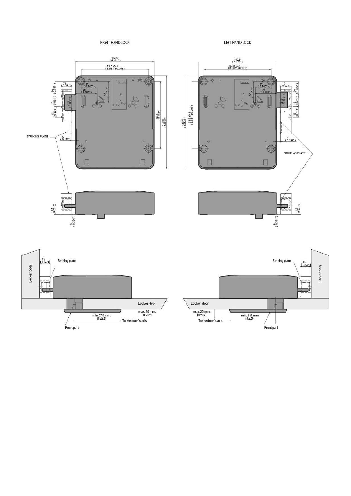
NLX1_LOCK INSTALLATION AND ASSEMBLY OJMAR 3
STRIKING PLATE WITH REINFORCEMENT
Design 1.2 - Measurements given in mm (inches)

NLX1_LOCK INSTALLATION AND ASSEMBLY OJMAR 4
FLAT STRIKING PLATE (WITH CHANNEL ON THE LOCKER BODY)
Design 1.3 - Measurements given in mm (inches)
NLX1_LOCK INSTALLATION AND ASSEMBLY OJMAR 5
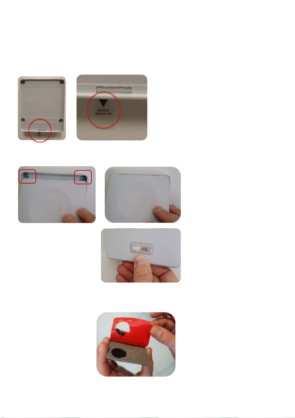
1.3. STEPS TO FOLLOW FOR ASSEMBLY
To assemble a NLX1 lock on a support or furnishing follow steps in this order:
1. Mark the holes according to Figure 1.4. Fixing holes must be done at the internal side of the locker door.
2. Drill the central hole of Ø23 (+0.1/0).
3. If necessary, drill the holes to fasten the lock.
4. Screw the lock with four fixing screws. Ensure that the plastic strip is visible after fixing the lock.
5. Assemble the rear cover:
a. Insert the two tabs of the cover at the top of the lock.
b. Press the cover at the bottom
for clipping the cover onto
the lock.
6. Assembly of the led viewer:
a. Clean the surface of the door and make sure it is dry.
b. Peel off the plastic film
from the emblem.
Click!!!
Other manuals for Nexo NLX1
2
Table of contents
Languages:
Other Ojmar Lock manuals

Ojmar
Ojmar Nexo NLX1 User manual

Ojmar
Ojmar OCS User manual

Ojmar
Ojmar OCS SMART User manual

Ojmar
Ojmar LOCKR COMBI 8001 Guide

Ojmar
Ojmar NEXO NL1 Guide

Ojmar
Ojmar OTS PULSE User manual

Ojmar
Ojmar OTS ADVANCE User manual

Ojmar
Ojmar INFOTERMINAL User manual

Ojmar
Ojmar OTS ADVANCE E-30 User manual

Ojmar
Ojmar OCS SMART User manual

Ojmar
Ojmar OCS SMART User manual

Ojmar
Ojmar OCS PRO User manual

Ojmar
Ojmar LOCKR COMBI 8001 User manual

Ojmar
Ojmar LOCKR 75 Operating instructions

Ojmar
Ojmar OTS BASIC User manual

Ojmar
Ojmar OTS ADVANCE User manual

Ojmar
Ojmar LOCKR COMBI User manual

Ojmar
Ojmar OCS SMART User manual

Ojmar
Ojmar OTS ADVANCE User manual

Ojmar
Ojmar Nexo NLX1 User manual


