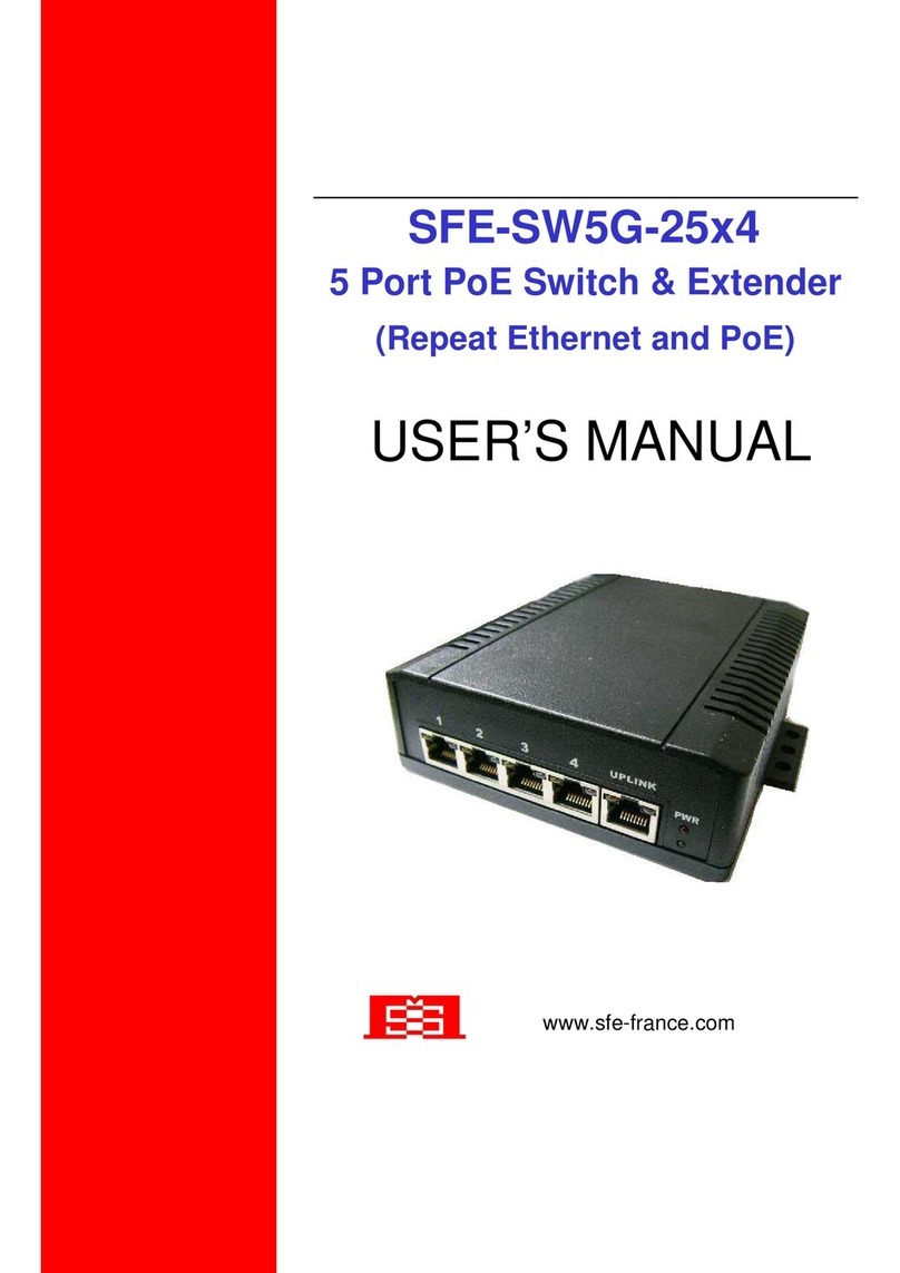
Q I G Quick Installation Guide
PRINTED ON RECYCLED PAPER
Version 1.1
Quick Installation Guide
Po we r
Red un da nt In pu t po wer
Pow er c on sum pt io n(Ty p. )
(Po E ou tp ut no t in cl ude d)
Du al DC i np ut s. 50 -5 7V DC on 6 -p in t er min al b lo ck
9 Wat ts
Ove rl oa d cu rre nt p ro tec ti on Pr ese nt
Ph ys ic al C harac te ri st ic
En clo su re I P-3 0
Di men si on ( W x D x H) 54.3 (W )x 10 8.5 (D )x 145 .1 (H ) mm (2 .1 4x 4.2 7x 5. 71 i nch .)
RS -23 2 Se ri al Co ns ol e Por t
Swi tc h Pr op ert ie s
Swi tc h la te ncy : 7 us
Swi tc h ba nd wid th : 16 Gbp s
Ma x. Nu mb er o f Ava ila bl e VL ANs : 40 95
VL AN ID R an ge : VI D 1 to 4 09 4
IG MP mu lt ic ast g ro up s: 25 6 fo r ea ch V LAN
Por t ra te li mi ti ng: U se r De fi ne
Se cur it y Fea tu re s
De vic e Bi nd ing s ec ur ity f ea tu re
En abl e/ di sab le p or ts, M AC b as ed p ort s ec ur ity
Por t ba se d net wo rk a cce ss c on tr ol (8 02 .1 x)
VL AN (8 02 .1 q) to s eg re gat e an d se cu re ne tw or k tra ff ic
Rad iu s ce ntr al ize d pa ss wo rd ma na ge men t
SN MPv 3 en cr ypt ed a ut hen ti ca ti on an d ac ce ss se cu ri ty
Ht tps / S SH e nha nc e ne tw ork s ec ur ity
So ftw ar e Fea tu re s
ST P/R ST P/ MST P (I EE E 80 2.1 D/ w/ s)
Red un da nt Ri ng ( O- Rin g) w it h re cov er y tim e le ss t han 3 0m s ov er 25 0 un it s
TOS /D if fse rv s up por te d
Qu ali ty o f Se rvi ce ( 80 2.1 p) f or r eal -t im e tra ff ic
VL AN (8 02 .1 Q) wi th V LA N tag gi ng a nd G VRP s up po rte d
IG MP Sn oo pi ng fo r mu lt ica st f il te rin g
IP -ba se d ba ndw id th m ana ge me nt
Ap pli ca ti on- ba se d QoS m an ag em ent
DO S/D DO S au to pr ev en tio n
Por t co nf igu ra tio n, s ta tu s, st at is tic s, m on ito ri ng , se cur it y
DH CP Se rv er / C lie nt s up por t
SM TP Cl ie nt
Mo dbu s TC P
NT P ser ve r
Ne two rk R edu nd an cy O- Rin g, O pe n-R in g, O -C hai n, M RP , MS TP (R ST P/ STP c om pa tib le )*N ote
RS -23 2 in R J4 5 con ne ct or wi th c on so le ca bl e. B au d ra te se tt in g: 11 52 00 bps , 8, N , 1
Wei gh t (g) 66 5 g
Ju mbo f ra me Up t o 9.6 K By te s
Wei gh t (g) 71 0 g 74 0 g72 2 g 73 5 g 73 5 g 74 0 g
En vi ro nm ental
-4 0 to 85 C ( -40 t o 18 5 F )
o o
St ora ge Tem pe rat ur e
-4 0 to 75 C ( -40 t o 16 7 F )
o o
Op era ti ng Tem pe rat ur e
5% t o 95% N on -c ond en si ngOp era ti ng Hu mi di ty
Re gu la to ry Appr ov al s
FC C Par t 15 , CIS PR ( EN 550 22 ) cl as s AEM I
EN 610 00 -4 -2 (E SD ), E N61 00 0- 4- 3 (RS ), E N6 100 0- 4- 4 (EF T), EN 610 00 -4 -5 (S ur ge ), EN6 10 00 -4- 6 (C S) , EN 610 00 -4 -8, E N6 10 00- 4- 11
EM S
IE C60 06 8- 2-2 7Sh ock
IE C60 06 8- 2-3 2
IE C60 06 8- 2-6Vi bra ti on
EN60950-1
Sa fet y
Fr ee Fa ll
Wa rr an ty
5 yea rs
Fa ul t Co nt act
Rel ay Re la y ou tpu t to c ar ry c apa ci ty o f 1A at 2 4V DC
Rev er se Po la ri ty Pr ot ec tio n
Pr ese nt
Q I G
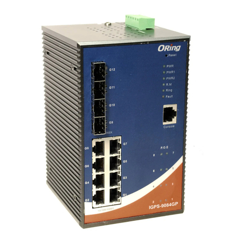
IGPS-9080 Series
IGPS-9080
G I G A B I T
I N D U S T R I A L
S W I T C H
P o E
Industrial Managed PoE Gigabit Switch
10/100Base-T(X) P.S.E. RJ-45 Port
Pin No.
TD+ with P oE P ow er i np ut +
# 1
Assig nm en ts
# 2
# 3
# 6
TD- with P oE P ow er i np ut +
RD+ with P oE P ow er i np ut -
RD- with P oE P ow er i np ut -
1000Base-T P.S.E. RJ-45 Port
Pin No.
BI_DA+ w it h Po E Po we r in pu t +
# 1
Assig nm en ts
# 2
# 3
# 4
BI_DA- w it h Po E Po we r in pu t +
BI_DB+ w it h Po E Po we r in pu t -
BI_DC+
BI_DC-
# 5
# 6
# 7
# 8
BI_DB- w it h Po E Po we r in pu t -
BI_DD+
BI_DD-
For pin assignments for different types of cables, please refer to the following
tables.
10/100 Base-T(X) MDI/MDI-X
Pin Number MDI port MDI-X port
1 TD+(transmit) RD+(receive)
2 TD-(transmit) RD-(receive)
3 RD+(receive) TD+(transmit)
4 Not used Not used
5 Not used Not used
6 RD-(receive) TD-(transmit)
7 Not used Not used
8 Not used Not used
Note: “+” and “-” signs represent the polarity of the wires that make up each
wire pair.
To connect the console port to an external mana gem ent d evi ce, y ou ne ed an R J-4 5 to
DB-9 cable, which is also supplied in the pac kag e. Be low i s the c ons ole p ort p in
assignment information.
Console Port Pin Definition
PC (male) pin assignment RS-232 with DB9 (female) pin
assignment (RJ45-DB9 cable) RJ45 pin assignment
PIN#2 RxD PIN#2 RxD PIN#2 RxD
PIN#3 TxD PIN#3 TxD PIN#3 TxD
PIN#5 GND PIN#5 GND PIN#5 GND
Wiring
The switch supports dual redu nda nt po wer s upp lie s, Po wer S upp ly1
(PWR1) and Power Supply 2 (PWR2). The co nne cti ons for PWR1,
PWR2 and the RELAY are located on the terminal block.
STEP 1: Insert the negative/positive wires into the V-/V+ t erm ina ls,
respectively.
STEP 2: To keep the DC wires from pulling loose, use a small flat-
blade screwdriver to tighten the wire-c lam p scr ews o n the f ron t of th e
terminal block connector.
PWR -1PWR -2
1A@ 24 V
V2- V 2+ V1- V 1+
Fau lt
Power inputs
The two sets of relay contacts of the 6-pin terminal bl ock c onn ect or ar e use d to de tec t use r-
configured events. The tw o wir es attached to the fault contacts form an open circuit when a
user-configured when an event is trigge red . If a us er- con fig ure d eve nt do es no t occ ur, th e
fault circuit remains closed.
Relay contact
1000Base-T MDI/MDI-X
Pin Number MDI port MDI-X port
1 BI_DA+ BI_DB+
2 BI_DA- BI_DB-
3 BI_DB+ BI_DA+
4 BI_DC+ BI_DD+
5 BI_DC- BI_DD-
6 BI_DB- BI_DA-
7 BI_DD+ BI_DC+
8 BI_DD- BI_DC-
1000Base-T RJ-45 Port
Pin Number Assignment
1 BI_DA+
2 BI_DA-
3 BI_DB+
4 BI_DC+
5 BI_DC-
6 BI_DB-
7 BI_DD+
8 BI_DD-
10/100 Base-T(X) RJ-45 Port
Pin Number Assignments
1 TD+
2 TD-
3 RD+
4 Not used
5 Not used
6 RD-
7 Not used
8 Not used
Resetting
To reboot the switch, press the button for 2-3 seconds.Reset
To restore the switch configurations back to the fact ory d efa ult s, pr ess t he bu tto n for 5 s eco nds .Reset
Grounding and wire routing help limi t the e ffects of noise due to electromagnetic interference (EMI).
Run the ground connection from the ground s cre ws to t he gr oun din g sur fac e pri or to c onn ect ing
devices.
Grounding
Configurations
After installing the switch, the green power LED should turn on. Please refer to the
following tablet for LED indication.
1. Launch the Internet Explorer and type in IP address of the switch. The default static IP ad dre ss is
192.168.10.1
2. Log in with default user name and password
(both are ). After logging in, you shouldadmin
see the following screen. For more information
on configurations , ple ase r efe r to th e use r
manual. For information on operating th e swi tch
using ORing’s Ope n-Vision management utility,
please go to ORing website.
Follow the steps to set up the switch:
LED Color Status Description
PWR Green On DC power on
PWR1 Green On DC power module 1 activated
PWR2 Green On DC power module 2 activated
R.M Green On Ring Master
On Ring enabled
Ring Green Blinking Ring structure is broken (i.e. part of the ring is
disconnected)
Fault Amber On Faulty relay (power failure or port disconnected)
PoE Green On Power supplied over Ethernet
10/100/1000Base-T(X) Gigabit PoE Ethernet ports
On Port link up
LNK/ACT Green Blinking Data transmitted
Green On Port link at 1000Mbps
Amber On Port link at 100MbpsSpeed
Green/Amber Off Port link at 10Mbps
Specifications
OR in g Sw it ch Mo de l IG PS -9 08 0
Ph ys ic al P orts
Te ch no lo gy
Et her ne t St and ar ds
IE EE 80 2. 3 fo r 10B as e-T
IE EE 80 2. 3u f or 10 0B as e-TX
IE EE 80 2. 3a b for 1 00 0B ase -T
IE EE 80 2. 3x f or Fl ow c on tro l
IE EE 80 2. 3a d for L AC P (L ink A gg re ga tio n Co nt rol P ro to col )
IE EE 80 2. 1p f or CO S (C la ss of s er vi ce )
IE EE 80 2. 1Q f or VL AN Tag gi ng
IE EE 80 2. 1w f or RS TP ( Ra pid S pa nn ing Tr ee P rot oc ol
IE EE 80 2. 1s f or MS TP ( Mu lti pl e Sp an nin g Tre e Pro to co l)
IE EE 80 2. 1x f or Au th en tic at io n
IE EE 80 2. 1A B for L LD P (L ink L ay er D isc ov ery P ro to co l)
IE EE 15 88 v2 c loc k sy nc hro ni za ti on
IE EE 80 2. 3a t PoE s pe cif ic at io n (up t o 30 Wa tt s pe r por t fo r P.S.E .)
10 /10 0/ 10 00B as e-T (X) P or ts
in R J45 A ut o MD I/M DI X
MA C Tabl e 8 K
Pr ior it y Qu eue s 8
Bu ffe r Si ze 4M bit
8
IG PS -9 08 0-2 4V
PoE O ut pu t Wat ts 24 0 Wat ts Ma x. 12 ~ 24V DC : 6 0Wa tt s Max .
24 ~ 5 7VD C : 12 0Wa tt s Max .
Du al DC i np ut s. 12 -5 7V DC on 6 -p in t er min al b lo ck
10 Wa tt s
67 8 g
Pr oce ss in g Sto re -a nd- Fo rwa rd
ORi ng Indust rial Netw o rking Cor p.
Copyrig ht© 201 4 ORing
All right s reserved .
TEL: +886-2-2218-1066
FAX: +886-2-2218-1014
Website: www. oringnet .com
E-mail: s upp ort@orin gnet.com


