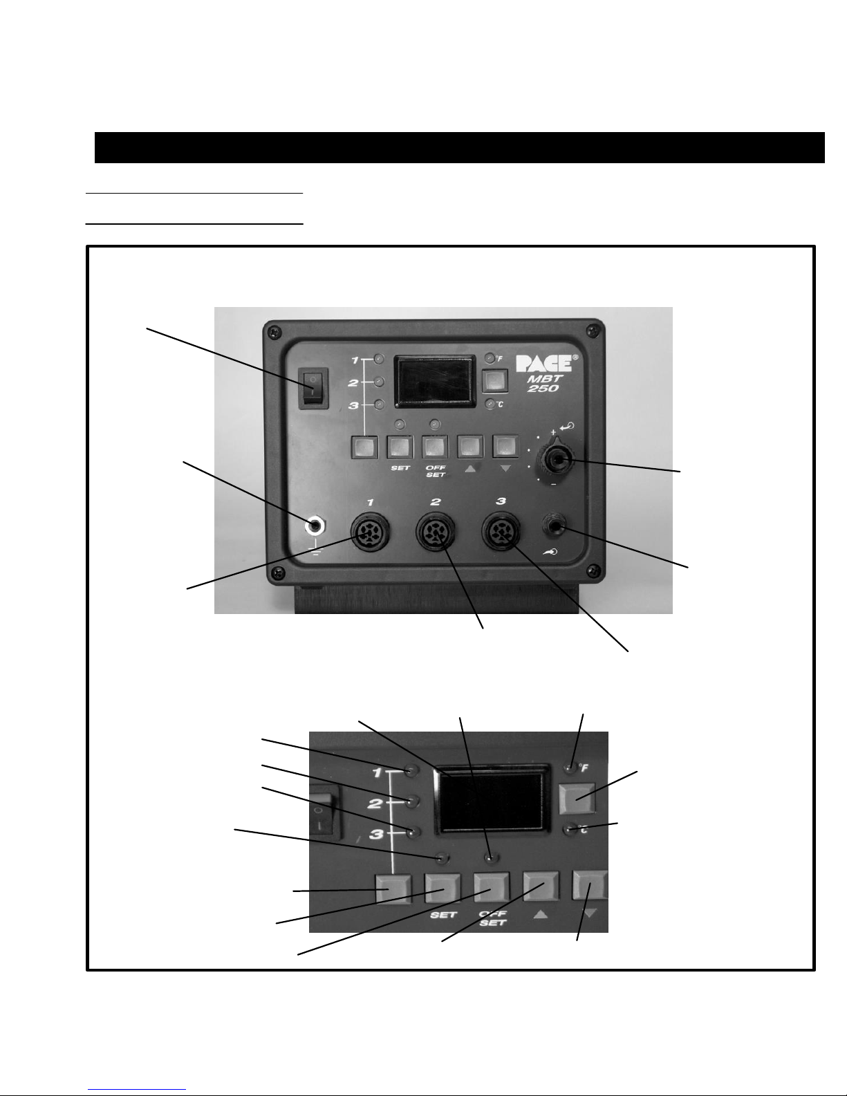
Parts Identification
Listed below is a description of the system power source parts. Use Figures 1 & 2 as a guide.
1. CH1POWERRECEPTACLE-Providespower,tipground,sensingcircuitryandfingerswitchconnection
fromMBT systemto handpiececonnectedto Channel1 (CH1).
2. CH2POWERRECEPTACLE-Providespower,tipground,sensingcircuitryandfingerswitchconnection
fromMBT systemto handpiececonnectedto Channel2 (CH2).
3. CH3POWERRECEPTACLE-Providespower,tipground,sensingcircuitryandfingerswitchconnection
fromMBT systemto handpiececonnectedto Channel3 (CH3).
4. POWERSWITCH-Turns systemON("1")and OFF("0");controlsinputpower tothesystem.
5. AUTOSNAP-VACPORT-Quickconnectfittingprovidesquick-risevacuumforSodr-X-Tractor,
ThermoPikandDualThermoPik handpieces. Vacuumispresentwhenhandpiecefingerswitchoroptional
foot pedal is actuated. Vacuumceases 1.2 seconds after switch (or foot pedal) released.
6. CONTROLLABLEPRESSUREPORT-Quickconnectfittingwithadjustablevalvewhichprovides
variableairflowforMiniThermoJethandpiece(inHotJetMode)andSodr-X-Tractorhandpiece. Air
pressure is present when handpiece finger switch or optional foot pedal is actuated. Air pressure ceases
1.2 seconds after switch (or foot pedal) is released.
7. DIGITALREADOUT-ProvidesathreedigitdisplayoftheCurrentChannel(channelwithilluminatedLED;
CH1,CH2orCH3)temperatureinformation. Thisincludes:OperatingTipTemperatureinTemperature
DisplayMode(normaloperation),TipOffsetConstantinTipOffsetMode,SetTipTemperatureinTipSet
ModeandotherinformationinCalibration(CAL)Mode.
8. °F/°CKEY-Selects°For°CdisplayofSetandOperatingTipTemperaturesandTipOffsetConstants.
9. °FLED- IlluminateswhenSet\OperatingTipTemperaturesandTipOffsetConstantsaredisplayedin°F.
10. °CLED-IlluminateswhenSet\OperatingTipTemperaturesandTipOffsetConstantsaredisplayedin°C.
11. CH1LED-IlluminateswhenChannel1(CH1)isthe“CurrentChannel”i.e.,thechannel(withconnected
handpiece\tip) whose temperature informationisdisplayed onthedigitalreadout.
12. CH2LED-IlluminateswhenChannel2(CH2)isthe“CurrentChannel”i.e.,thechannel(withconnected
handpiece\tip) whose temperature informationisdisplayed onthedigitalreadout.
13. CH3LED-IlluminateswhenChannel3(CH3)isthe“CurrentChannel”i.e.,thechannel(withconnected
handpiece\tip) whose temperature informationisdisplayed onthedigitalreadout.
14. CHSELECTKEY-SelectstheCurrentChannel(among"ActiveChannels"i.e.,thosewithaconnected
handpiece).
15. TIPSETKEY-AllowstheoperatortoadjusttheSetTipTemperatureforthe handpiece\tipcombination
connected to the Current Channel. Places the system in the Tip Set Mode.
7