manuals.online logo
Brands
  1. Home
  2. •
  3. Brands
  4. •
  5. Parker
  6. •
  7. Control Unit
  8. •
  9. Parker CK-1 Guide

Parker CK-1 Guide

Refrigerating Specialties Division 1
ISO 9001-2000 CERTIFIED
CHECK VALVE
Type CK-1 DN
Port Size 20 - 150mm (3/4” - 4”)
Suitable For: Ammonia, R12, R22, R502
and Other Common Refrigerants
Features
• Manual Opening Stem
• Low Pressure Drop
• Piston Type Gravity Closing
• Flanged
• Design Pressure (PS): 28 bar (406 psig)
• Rugged - Heavy Duty
• Body Material made from GGG40.3
• Complies with Pressure Equipment Directive 97/23/EC
Description
These piston type, gravity closing, heavy duty check
valves are suitable for Ammonia, R-12, R-22, R-502,
other refrigerants, certain oils and or fluids approved for
use in refrigeration. All CK1 check valves are flanged and
have a manual opening stem for manual operation. They
may be ordered with male adapter rings (through 4” size)
for close coupling. The 20-32 mm (3/4 - 1-1/4”) port size
have a PTFE seat; larger valves have a metal to metal
seat. A minimum pressure difference of .03 bar (0.5 psi)
is required to open the valve.
BULLETIN DN 50-10C
September 2007
Installation, Service, and Parts Information
Fig. 1: CK1-DN Cross-Section
Purpose
The Type CK1 Check Valves prevent backward flow of
fluid in refrigerant suction, hot gas or liquid lines. They
are recommended for compressor discharge lines, also
for liquid lines and suction lines with temperatures as
low as -30°C (-25°F).
Principles of Operation
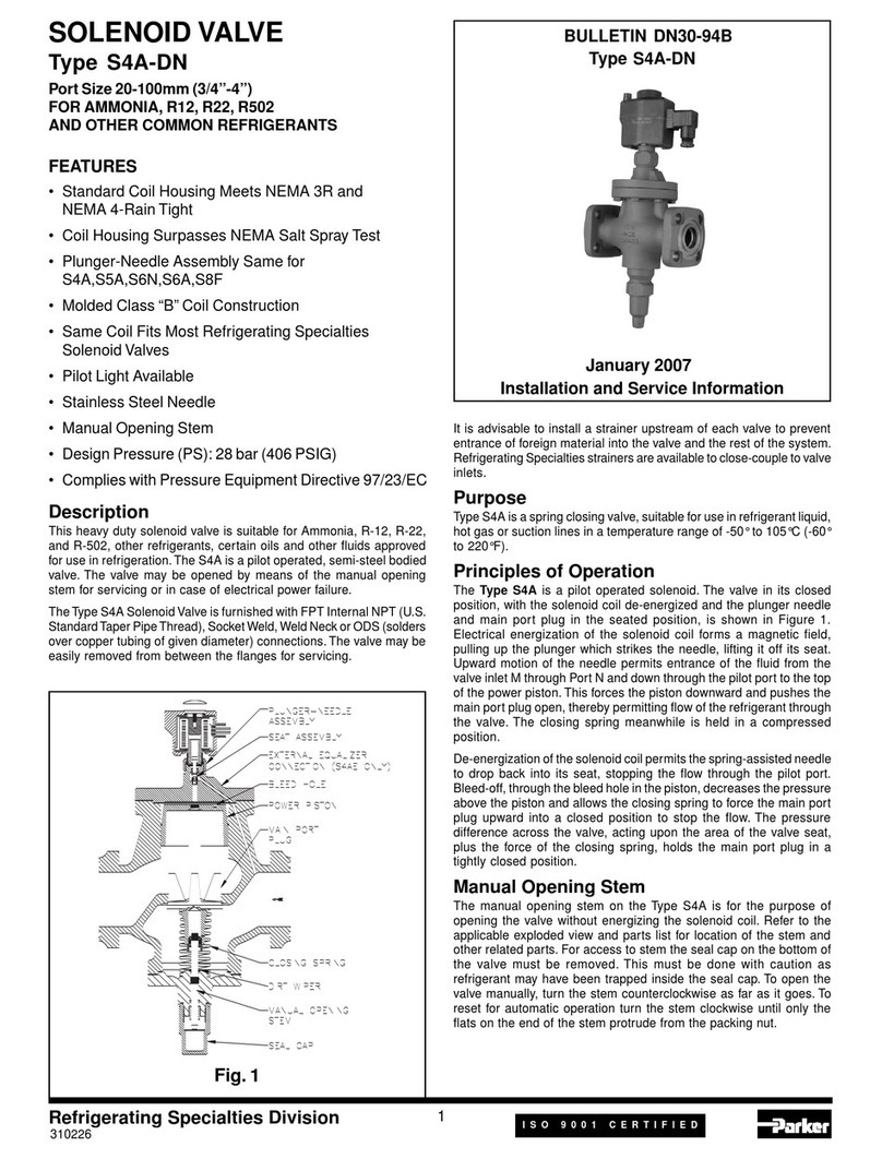
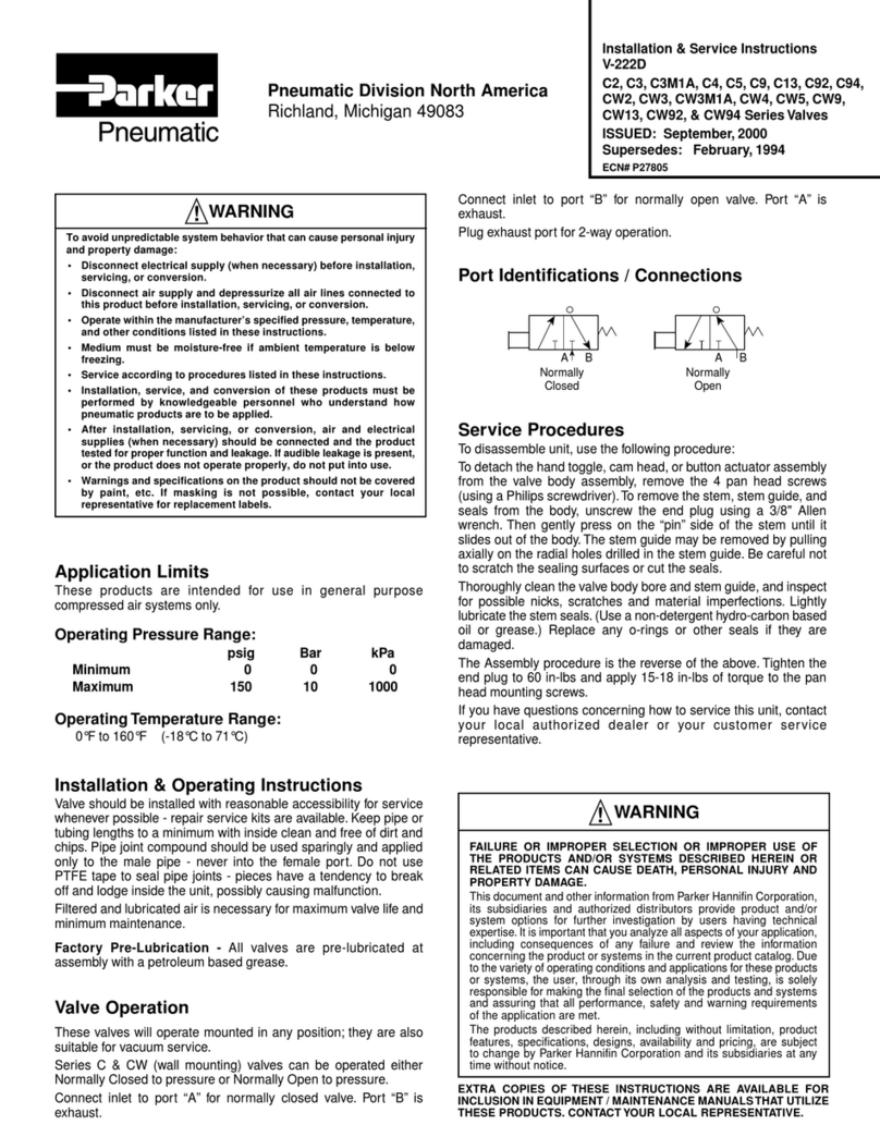
This piston type check valve opens by the pressure
difference between valve inlet and outlet. The pressure
difference must be a minimum of .03 bar (0.5 psi).
When upstream pressure exceeds downstream pressure,
the pressure on the bottom side of the piston-main valve
will lift the assembly and allow flow through the valve. On
opening, pressure above the piston-main valve assembly
will be relieved through the piston bleed hole, permitting
the piston to travel its full vertical distance and open the
valve to its full open position.
When upstream and downstream pressures are qualized,
the weight of the piston-main valve will cause it to
drop tight against its seat bead and stop flow. Should
downstream pressure rise, the additional pressure acting
on the top of the valve seat will further assist in seating
the valve closed.
Manual Opening Stem (Fig. 1)
If it is desired to hold open the CK1 check valve manually
this procedure should be followed. For access to the
stem, the seal cap on the bottom of the valve must be
removed. This must be done with caution as refrigerant
may be trapped inside the seal cap. Manual opening is
accomplished by turning the stem clockwise until only
the flats on the end of the stem protrude from the packing
nut. To reset for automatic operation turn the stem
310227
DIMENSIONAL DATA
PORT SIZE A B C D E F G H J
mm in. mm in. mm in. mm in. mm in. mm in. mm in. mm in. mm in. mm in.
20, 25 3/4, 1 191 7.5 102 4.0 158 6.2 89 3.5 117 4.6 239 9.4 216 8.5 13 0.5 265 10.4
32 1-1/4 219 8.6 122 4.8 203 8.0 96.5 3.8 117 4.6 305 12.0 256 10.1 15 0.6 620 12.6
40, 50 1-5/8, 2 270 10.6 139.7 5.5 251 9.9 129.5 5.1 129.5 5.1 371 14.6 307 12.1 15 0.6 414 16.3
65 2-1/2 303 11.9 142.2 5.6 251 9.9 160 6.3 147.3 5.8 401 15.8 331 13.0 25 1.0 424 16.7
75 3 384 15.1 216 8.5 311 12.2 167.5 6.6 167.6 6.6 478 18.8 389 15.3 29 1.1 500 19.7
100 4 427 16.8 217 8.6 366 14.1 208.3 8.2 190.5 7.5 571 22.5 450 17.7 32 1.3 615 24.2
125 5 496 19.5 298.4 11.7 381 15.0 198.1 7.8 228.6 9 576.6 22.7 485 19.1 30.5 1.2 ---- ----
150 6 537 21.1 355.6 14.0 514.3 20.2 180 7.1 294.6 11.6 706.1 27.8 617 24.3 35.6 1.4 ---- ----
Refrigerating Specialties Division 2
Fig. 2: CK1-DN Dimensions
Component Material
Body Ductile Iron GGG 40.3
Seal Cap, A4A/S4A Aluminum
Cover, Top Ductile Iron GGG 40.3
PRESSURE CONTAINING COMPONENTS
CK1 1-1/4” TO 4”
Refrigerating Specialties Division 3
Item Description Item Description
2 Bolt 10 Washer
3 Cover 11 Opening Stem
4 Gasket, Cover 12 Body
5 Piston Plug Asm 15 Gasket
6 Seal Cap 16 Bolt
7 Gasket, Cover 17 Cover Bottom
8 Packing Nut 18 Gasket
9 Packing
Fig. 3: Part Kits List Price Schedule Industrial and Flo-Con (PK)
REPLACEMENT PARTS
counterclockwise as far as it goes. Loosen packing nut
before turning stem, and retighten after turning stem.
Installation
Protect inside of valve from dirt, chips and moisture
during installation. Be sure to remove protective plugs
from valve before installation. Install the valve in an
accessible location for servicing. DO NOT INSTALL
THE CHECK VALVE AT THE INLET OF A SOLENOID
VALVE, OR A REGULATOR WITH AN ELECTRIC SHUT-
OFF FEATURE. DO NOT INSTALL AT THE INLET OF AN
OUTLET PRESSURE REGULATOR IN A SYSTEM WHERE
LIQUID MAY BE TRAPPED BETWEEN TWO VALVES.
Check Valves when used with such valves should always
be installed at the outlet of the valves. The valve must
be installed with the flow arrow on the valve pointing in
the direction of permissible fluid flow through the valve.
The Type CK1 are for installation on horizontal pipelines
only. The valve must be installed with the cover on top.
Tighten the flange bolts evenly. Before putting the valve
into operation check the manual opening stem. For
automatic operation, turn the stem counterclockwise as
far as it goes; turn clockwise for manual open position.
The CK1 Check Valves may be closed-coupled to R/S
Control Valves and most hand valves by using a Special
R/S Male Adapter Ring.
Parker Hannifin Corporation  Refrigerating Specialties Division
2445 South 25th. Avenue  Broadview, IL 60155-3891
Telephone: (708) 681-6300  Fax: (708) 681-6306
4
Service Pointers
Dirt or other foreign material in the system is the
greatest single cause of valve malfunction. Before
disassembling a check valve for servicing, read and
become familiar with the Safe Operation Instructions
in this bulletin as well as in the current issue of Safety
Bulletin RSB.
Check the following chart for possible symptoms and
corrections.
Symptom Probable
Reason Correction
Valve does not
close or there is
leakage through
valve.
Stuck piston due
to dirt or chips.
Disassemble
valve and clean
thoroughly.
Burrs on piston. Polish or replace
piston.
Manual stem is
in open position
(turned com-
pletely in).
Unscrew manual
stem (turn coun-
terclockwise)
Eroded or worn
seat on piston
main valve.
Replace entire
piston-main valve
assembly.
Valve does not
open.
Stuck piston,
due to dirt or
chips.
Disassemble
valve and clean
thoroughly.
Safe Operation (See also Bulletin RSBCV)
People doing any work on a refrigeration system must
be qualified and completely familiar with the system and
the Refrigerating Specialties Division valves involved, or
all other precautions will be meaningless. This includes
reading and understanding pertinent Refrigerating
Specialties Division Product Bulletins, and Safety
Bulletin RSBCV prior to installation or servicing work.
Where cold refrigerant liquid lines are used, it is
necessary that certain precautions be taken to avoid
damage which could result from liquid expansion.
Temperature increase in a piping section full of solid
liquid will cause high pressure due to the expanding
liquid which can possibly rupture a gasket, pipe or
valve. All hand valves isolating such sections should be
marked, warning against accidental closing, and must
not be closed until the liquid is removed. Check valves
must never be installed upstream of solenoid valves, or
regulators with electric shut-off, nor should hand valves
upstream of solenoid valves or downstream of check
valves be closed until the liquid has been removed. It is
advisable to properly install relief devices in any section
where liquid expansion could take place.
Avoid all piping or control arrangements which might
produce thermal or pressure shock.
For the protection of people and products, all refrigerant
must be removed from the section to be worked on
before a valve, strainer, or other device is opened or
removed. Flanges with ODS connections are not suitable
for ammonia service.
Warranty
All Refrigerating Specialties products are warranted
against defects in workmanship and materials for a
period of one year from date of shipment from factory.
This warranty is in force only when products are properly
installed, field assembled, maintained, and operated in
use and service as specifically stated in Refrigerating
Specialties Catalogs or Bulletins for normal
refrigeration applications, unless otherwise approved in
writing by Refrigerating Specialties Division. Defective
products, or parts thereof returned to the factory with
transportation charges prepaid and found to be defective
by factory inspection will be replaced or repaired at
Refrigerating Specialties option, free of charge, F.O.B.
factory. Warranty does not cover products which have
been altered, or repaired in the field, damaged in transit,
or have suffered accidents, misuse, or abuse. Products
disabled by dirt or other foreign substances will not be
considered defective.
THE EXPRESS WARRANTY SET FORTH ABOVE
CONSTITUTES THE ONLY WARRANTY APPLICABLE
TO REFRIGERATING SPECIALTIES PRODUCTS, AND
IS IN LIEU OF ALL OTHER WARRANTIES, EXPRESSED
OR IMPLIED, WRITTEN OR ORAL, INCLUDING ANY
WARRANTY OF MERCHANTABILITY, OR FITNESS FOR
A PARTICULAR PURPOSE. No employee, agent, dealer
or other person is authorized to give any warranties
on behalf of Refrigerating Specialties, nor to assume,
for Refrigerating Specialties, any other liability in
connection with any of its products.
This manual suits for next models

10

Other Parker Control Unit manuals

Parker PSSTR4M12A Installation and maintenance instructions

Parker

Parker PSSTR4M12A Installation and maintenance instructions

Parker IQAN-XC21 User manual

Parker

Parker IQAN-XC21 User manual

Parker PHD Series User manual

Parker

Parker PHD Series User manual

Parker Series DFplus User manual

Parker

Parker Series DFplus User manual

Parker S4A-DN Operating and installation instructions

Parker

Parker S4A-DN Operating and installation instructions

Parker HASV08R User manual

Parker

Parker HASV08R User manual

Parker CK-6D User manual

Parker

Parker CK-6D User manual

Parker LINKnet TechBox Series User manual

Parker

Parker LINKnet TechBox Series User manual

Parker CK-2W User manual

Parker

Parker CK-2W User manual

Parker CK5-DN User manual

Parker

Parker CK5-DN User manual

Parker IQAN-LC5-C02 User manual

Parker

Parker IQAN-LC5-C02 User manual

Parker TPQ Series User manual

Parker

Parker TPQ Series User manual

Parker TFP Series User manual

Parker

Parker TFP Series User manual

Parker PEV Service manual

Parker

Parker PEV Service manual

Parker AC30V Series User manual

Parker

Parker AC30V Series User manual

Parker PWD Series User manual

Parker

Parker PWD Series User manual

Parker IOTA ONE Series User manual

Parker

Parker IOTA ONE Series User manual

Parker Series DFplus User manual

Parker

Parker Series DFplus User manual

Parker 810 Series Assembly instructions

Parker

Parker 810 Series Assembly instructions

Parker DN80 User manual

Parker

Parker DN80 User manual

Parker D1FH series User manual

Parker

Parker D1FH series User manual

Parker DP-V1 User manual

Parker

Parker DP-V1 User manual

Parker C10 User manual

Parker

Parker C10 User manual

Parker SciLog DINCon Assembly instructions

Parker

Parker SciLog DINCon Assembly instructions

Popular Control Unit manuals by other brands

Spirax Sarco HM Series Installation and maintenance instructions

Spirax Sarco

Spirax Sarco HM Series Installation and maintenance instructions

BERMAD 450-60 manual

BERMAD

BERMAD 450-60 manual

Heicko HD15BT user manual

Heicko

Heicko HD15BT user manual

National Instruments NI-9208 CALIBRATION PROCEDURE

National Instruments

National Instruments NI-9208 CALIBRATION PROCEDURE

RAK 3172 WisDuo LPWAN quick start guide

RAK

RAK 3172 WisDuo LPWAN quick start guide

Wandel & Goltermann OLA-35 Description and operating manual

Wandel & Goltermann

Wandel & Goltermann OLA-35 Description and operating manual

Viking TMS-RDMA user guide

Viking

Viking TMS-RDMA user guide

Danfoss EH Series Service manual

Danfoss

Danfoss EH Series Service manual

Motorola MVME2300SC Series Installation and use

Motorola

Motorola MVME2300SC Series Installation and use

HYDAC International FMMHP Operating and maintenance instructions

HYDAC International

HYDAC International FMMHP Operating and maintenance instructions

Siemens 3VM9.88-0LB10 operating instructions

Siemens

Siemens 3VM9.88-0LB10 operating instructions

Stacore ADVANCED user manual

Stacore

Stacore ADVANCED user manual

Fluke DSP-PM14A instruction sheet

Fluke

Fluke DSP-PM14A instruction sheet

Greenheck KFCC Installation, operation and maintenance manual

Greenheck

Greenheck KFCC Installation, operation and maintenance manual

Chamberlain 041-0200-000 instructions

Chamberlain

Chamberlain 041-0200-000 instructions

Jetter JX3-COM-PND installation manual

Jetter

Jetter JX3-COM-PND installation manual

Vantron MOB-WBT-56 user manual

Vantron

Vantron MOB-WBT-56 user manual

Barco UDX-4K40 installation manual

Barco

Barco UDX-4K40 installation manual

manuals.online logo
manuals.online logoBrands
  • About & Mission
  • Contact us
  • Privacy Policy
  • Terms and Conditions

Copyright 2025 Manuals.Online. All Rights Reserved.