manuals.online logo
Brands
  1. Home
  2. •
  3. Brands
  4. •
  5. Philco
  6. •
  7. Radio
  8. •
  9. Philco 66 User manual

Philco 66 User manual

-.....- ·
PHILCO
REG.U.S.PAT.Off
Service Bulletin,.,. No. 197
Model 66
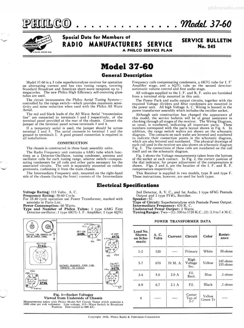
Model 66 is a five-tube superheterodyne radio receiver, capable of receiving either standard
broadcasts (and police calls up to 1720 K.C.), or short-wav e stations within a frequency range of 5.5
to 16.0 megacycles. The frequency range on standard broadcast is 540-1720 kilocycles.
The tubes used are: · Type 6A7 detector-oscillator, type 78 intermediate frequency, type 75 2d
detector, type 42 output and type 80 rectifier. The intermediate frequency of the Model 66 is 460
K.C . and the power consumption is 60 watts.
Tube Socket Voltages-Line Voltage 115 Power Transformer Data
Tube 6A7 78 75 42 80 Terminals Volts Circuit ColorofLeads
--- --- ---
Circuit Det.Osc. I. F. 2d Del. Output Reel. 1-2 105-125 Primary White
--- --- --- --- 3-5 6.3 Filaments Black
Filament(F-F).. ... .... .. 6.3 6.3 6.3 6.3 5.0
--- --- --- --- 6-7 5.0 Filamentof80 Blue
Plate (P-K).... . .. .. . .. .. 260 260 160 250 340
--- - -- -- - 8-10 680 Plates of80 Yellow
Screen (SG-K)........ .. . . 85 85 ... 260 ... 4 ... Center Tap of 3-5 Black-Yellow Tracer
--- ---
Cathode (K-F).... ... .. .. 2.1 2.2 0 0 ... 9 ... Center Tap of 8-10 Yellow-Green Tracer
6A7-GI-K:20;6A7-G2-K:130.
The above voltageawereobtained by using a high resistancemulti-range DC voltmeter,and an ACvoltmeter for filaments. Tests made with test prods appliedto
tube socketsat undersideof chassis(see Fig. I). Volumecontrolat maximum,dial at lowfrequencyend of scale.
TONE WAVEBAND
CONTR.OL SWITCH
75
6A7
B
□
RECTIFIER
7B
0ET.05C. bl so
,.F. 00
Fig. 1-Tube Sockets(Underside) ANTENNA
Fig.2-Top Viewof Chassis
Adjusting Compensating Condensers
The adjustment of the compensating condensers in Model
66 Receiver requires the use of an accurate signal generator
such as Philco Model 024, an efficient output meter (Philco
Model 012 or Model 025 are recommended), and a suitable
fibre hex wrench. Connect the output meter to the plate and
cathode prongs of the 42 output tube.
Adjustments are made in the following order:
(1)-1. F. (Intermediate Frequency)-Remove grid ~lip
from cap on 6A7 tube and connect antenna lead from signal
generator to cap of tube . Connect ground lead to ground post
on set. Turn on set and signal generator; set wave switch of
latter to 460 K. C. (the I. F. of Model 66) and dial of set
at 540, wave band switch to left. Adjust each of the four I. F.
compensating condensers @, @, @ and @ in turn so that
maximum reading is obtained in the output meter. H the
meter reading goes off scale, adjust the attenuator on the
signal generator so as to get a lower reading. These I. F.
condensers (visible in Fig. 4) are adjusted by inserting the
hex wrench thru the holes in rear of chassis sub-base (except
one to extreme left when facing rear of set). Two of the holes
are covered by small metal buttons which can be removed
temporarily by hand.
(2)-WAVE TRAP - Replace grid clip on cap of 6A7 tube
and connect antenna lead from signal generator to antenna
post on set. Set signal generator at 460 K. C. and adjust wave
trap © so as to get MINIMUM reading in output meter.
(3)-ANT. and OSC. H. F.- These adjustments (1) and
@ are located on top of the tuning condenser assembly at
right (facing front of set) and adjusted from above. The
"ANT" (1)is nearest front of set. Set signal generator at 1700
and dial of set at 1700and adjust these two condensers to get
maximum output meter reading.
(4)-OSC. L. F.-This condenser@ is located underneath
chassis (see Fig. 4) and is reached from underneath. ,Set dial
of set and signal generator switch at 600, and adjust for
maximum reading.
PHILCO RADIO & TELEVISION CORPORATION
t~f;i~
9r:u.s.A. Service Department
philcoradio.com
fil
L----11 I ~I J
lt;; ®-@
Fig.3-Schematlc Design
"i
0
a:i
....
:,.
0
a:i
I i"i
~rE-'- I I
~+~
Replacement Parts for Model 66
No. on
Figs. Description PartNo.
(D Wave Trap ...•................... . ...•... . .....•. 38-5199
@ Wave-band Switch................................ . . 42-1066
@ Resistor (10,000 ohms) (Brown-Black-Orange) ... .. .... 33-1000
© Antenna Transformer ............................... 32-1412
® Condenser (.000015 Mfd.)............ •........ • •.... 30-1030
@ Tuning Condenser Assembly ....... , ......... .. . ..... 31-1231
® Compensating Condenaer (ANT) .. . .................. Part of@
@ Resi,tor (200 ohms Flexible) (Red-Black-Brown) .. :. . . . 7217
@ Condenser (.05 Mfd. Tubular) .. . .................... 30-4020
@) Resistor (50,000 ohms) (Green-Green-Orange). . .... . . . . 6098
@ Compensating Condenser (OSC. HF) ................. Part of@
@ Condenser (.003 Mfd. Mica) •••..••••.•..•...... .. ... 30-102~
@ Compensating Condenser (Osc. I. F.) ...... . . .. ....... 04000-S
@ Condenser (.0008 Mfd. Mica). . . . . . . . . . . . . . . . . . . . . . . . 5878
@ Resistor (32,000 ohms) (Orange-Red-Ora nge) ..... . . ... 5279
@ Oscillator Transformer .... . ............... .. ........ 32-1413
@ Compensating Condenser (1st I. F. Pri.)......... .. . . . . 04000.M
@ 1st I. F. Transformer. . . . . . . . . . . . . . . . . . . . . . . . . . . . . . . 32-1414
@ Compensating Condenser (1st I. F. Secondary) ...... . .. 04000M
@) Resistor (400 ohms Flexible) ......................... 33-3016
@ Condenser (.05 Mfd. Tubular) ...................... . 30-4020
@ Compensating Condenser (2d I. F.!Primary) .... . ...... 04000M
List
Price
S0.30
.90
.25
.85
.35
3.65
.20
.35
.25
.60
.35
35
.25
.60
.20
1.00
.20
.20
.35
.20
No. on List
Figs. Description PartNo. Price
@ 2d I. F Transformer ......... .. .... ...........••.... 32-1415 $1.00
@ Compensating Condenser (2d l. F. Secondary) ......... 04000.J .20
@) Resistor (50,000 ohms) (Green-Brown-Orange}......... 6098 .25
@ Condenser (.0001 Mfd. Twin Bakelite Block) .......... 8035-B .25
® Condenser (.1 Mfd. Tubular) .............. ..... ..... 30-4170 .35
@ Resistor (70,000 ohms) (Violet-Black-Orange) ....... ... 33-1115 .25
@) Resistor (70 000 ohms) (Violet-Blsok-Orange) ...... . ... 33-1115 .25
@) Condenser (.00011 Mfd. Mica) .......... .. ...... ..... 30-1006 .35
® Condenser (.02 Mfd. Tubular) ................... .... 30-4113 .30
@ Resistor (500,000 ohms) (Yellow-White-Yellow)........ 6097 .25
@ Tone Control. . . . . . . . . . . . . . . . . . . . . . . . . . . . . . . . . . . . . . 30-4192 .50
@ Condensers in Tone Control. . . . . . . . . . . . . . •. . . . . . . . . . Inside @
@ Output Transformer... .. . ........ . . . ... ••.. ...... .. 32-7019 1.25
@ Voice Coil & Cone Assembly (S-12). ..... . ........ . .. . 36-3014 .60
@ Field Coil and Pot. Assembly (S-12).................. 3&-3341 2.75
@ Resistor (2 Megohms) (Red-Black-Green) ........ . .... 33-1025 .25
@ Volume Control and On-OffSwitch . .................. 33-5006 1.45
@ Condenser (.01 Mfd.) (Bakelite Block)..... ... ........ 3903-AB .25
@ Resistor (I Megohm) (Brown-Black-Green) ............ 33-1096 .25
@ ': ondenser (.1 Mfd.) ........................... . .... 30-4122 .35
@ lleoistor (.1 Meg.) (White-White-Orang e) .............. 6099 .25
@ Resistor (B. C. Wire-wound) (22, 235 ohms) ...... ..... 33-3037 .20
I J
\
Fig.4-BaN View
No. on List
Figs. Description PartNo. Price
@ Resistor~(.! Meg.) (White-White-Orange) ......... .... 6099 S0.25
@ Condenser (.05 Mfd. Tubular ).. . . . ...... . ..... . . .. .. 30-4123 .35
@ Resistor (37,000 ohms) (Orange-Violet-Orange) .... ..... 33-1098 .35
@ Filter Choke.......................... ..... ........ 32-7018 1.50
@ Condenser (Eleetrolytic-6 Mfd.) ................ .... . 30-2021 1.55
® Condenser (Eleetrolytic-8-8 Mfd.) ................ . .. 30-2028 2.40
® Condenser (.09 Mfd. Bakelit e Block) ... .. .. .. . . . . . .... 4989-D .35
@ Power Transformer.. .. . . . . .......... ... .. . ....... . 8046 3.45
@ Condenser (.015 Mfd. Bakelite Block) ............... . . 3793-W .35
@ Condenser (.05 Mfd. Tubular) ........... .•• .. . . . .... 30-4020 .35
@ Dial Light .... .. ..... ..... . ........... .• ..... .... .. 6608 .11
Four Prong Socket.......... . ........•.........•.... 7544 .JO
Six Prong Socket.......... ••. . ...... ••...... .• •. ... 7547 .JI
Seven Prong Socket ..................•....... . . •.. .. 27-6005 .11
Tube Shield.. . ... . .......... .. ..... . . .....•.••..... 28-1107 .10
Chassis Mountin g Screw ..... ......... . . .. .. •. . ..... W-567 3.00C
Chassis Mountin g Washer (Metal) ...........•. •. ..... W-315 .50C
Chassis Mounting Washer (Rubber) .. . .. .. •.. •. ..... . 5189 .04
Knob (Large) .. ... ·-············ ·· ·· · 27-4051 .10
Knob (Small) ................ . .. .................. 27-4052 .10
Dial Assembly................... . ..... . . .. . . •.. 31-1234 .30
Dial Scale....... ... ........ . . .. . . •.... .... •..... 27-5057 .JO
A. C. Cord and Plug Assembly ..... . ... . . . . . .• • ..... . L-943A .60
1,
philcoradio.com

Other Philco Radio manuals

Philco 37-660 User manual

Philco

Philco 37-660 User manual

Philco 37-620 User manual

Philco

Philco 37-620 User manual

Philco CSP790BC User manual

Philco

Philco CSP790BC User manual

Philco 121 User manual

Philco

Philco 121 User manual

Philco 643 User manual

Philco

Philco 643 User manual

Philco 121 User manual

Philco

Philco 121 User manual

Philco 37-675 User manual

Philco

Philco 37-675 User manual

Philco 80 User manual

Philco

Philco 80 User manual

Philco 116 User manual

Philco

Philco 116 User manual

Philco 96 User manual

Philco

Philco 96 User manual

Philco 28 User manual

Philco

Philco 28 User manual

Philco 623 User manual

Philco

Philco 623 User manual

Philco 650 User manual

Philco

Philco 650 User manual

Philco 144 User manual

Philco

Philco 144 User manual

Philco 121 User manual

Philco

Philco 121 User manual

Philco 118 User manual

Philco

Philco 118 User manual

Philco 37-670 User manual

Philco

Philco 37-670 User manual

Philco 15 Series Reference manual

Philco

Philco 15 Series Reference manual

Philco 37-640 User manual

Philco

Philco 37-640 User manual

Philco 37-630 User manual

Philco

Philco 37-630 User manual

Philco 16 Reference manual

Philco

Philco 16 Reference manual

Philco 611 User manual

Philco

Philco 611 User manual

Philco 29 User manual

Philco

Philco 29 User manual

Philco 121 User manual

Philco

Philco 121 User manual

Popular Radio manuals by other brands

Sony ICF404 operating instructions

Sony

Sony ICF404 operating instructions

EINHELL TE-CR 18 Li-Solo Original operating instructions

EINHELL

EINHELL TE-CR 18 Li-Solo Original operating instructions

Telex TK-80 Series Application guide

Telex

Telex TK-80 Series Application guide

GME CM40 Series Programming manual

GME

GME CM40 Series Programming manual

Ericsson MGP 148 Maintenance manual

Ericsson

Ericsson MGP 148 Maintenance manual

Belkin F8Z179TTP user manual

Belkin

Belkin F8Z179TTP user manual

Uniden BearCat BC 855XLT operating guide

Uniden

Uniden BearCat BC 855XLT operating guide

Sangean DDR-3 Operating	 instruction

Sangean

Sangean DDR-3 Operating instruction

LENCO DIR-140 user manual

LENCO

LENCO DIR-140 user manual

Ranger Electronic VX-129CN owner's manual

Ranger Electronic

Ranger Electronic VX-129CN owner's manual

Makita MR004G instruction manual

Makita

Makita MR004G instruction manual

LENCO PIR-645 user manual

LENCO

LENCO PIR-645 user manual

Motorola Radius operating instructions

Motorola

Motorola Radius operating instructions

Hyundai RA 701C instruction manual

Hyundai

Hyundai RA 701C instruction manual

Hytera HM652 user manual

Hytera

Hytera HM652 user manual

NGS Nomad user manual

NGS

NGS Nomad user manual

Tecsun PL-380 Operation manual

Tecsun

Tecsun PL-380 Operation manual

Retevis RT99 user manual

Retevis

Retevis RT99 user manual

manuals.online logo
manuals.online logoBrands
  • About & Mission
  • Contact us
  • Privacy Policy
  • Terms and Conditions

Copyright 2025 Manuals.Online. All Rights Reserved.