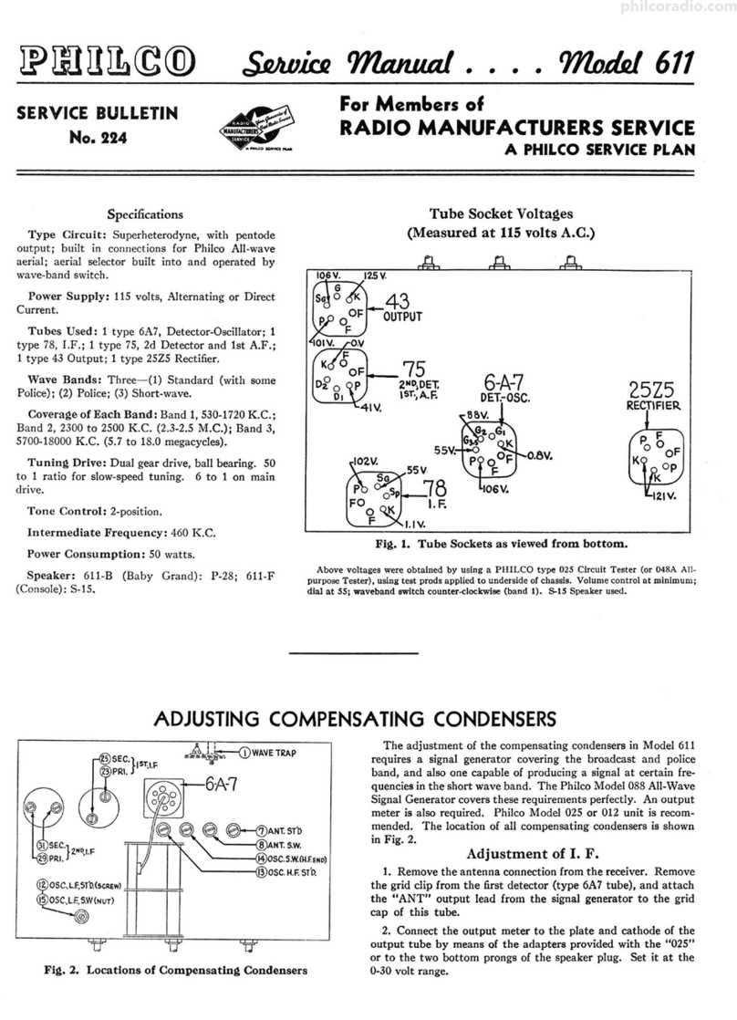
Philco 121 User manual

• • • • • • • • • • • • • 'Yfli,d,d_37-610
Special Data for Members of
RADIOMANUFACTURERSSERVICESERVICEBULLETIN
No. !49
A PHILCO SERVICE PLAN
Model 37-610
Codes, 121-122
General Description
Model 37-610 is a 5 tube superheterodyne receiver for oper.ation
on alternating current, having three tuning ranges, covering
standard broadcast and short-wave frequencies and using the New
Ph'ilco High-Efficiency self-centering glass tubes .
The circuit includes the Philco Foreign Tuning System--con-
trolled by the rang e switch-providing maximum sensitivity and
noise reduction when used with the Philco High Efficiency Aerial,
supplied with the receiver.
The red and black leads of the High-Efficiency Aerial "trans- .
mission line" are connected to terminals 1 and 2 respectively, of
the termin al panel provided at the rear of the chassis. Connect
the jumper of the terminal panel across terminal 3 and 4.
If a temporary aerial is used, the jumper should be across
terminal 2 and 3. The aerial connects to terminal 1 and the
ground to terminal 3.
A good ground connection is desirable in all installations-with
the Philco High-Efficiency Aerial, a ground lead and ground clamp
are provided. Make the ground connection from the nearest
water or radiator pipe to terminal 3 on the terminal panel.
CONSTRUCTION
The chassis is constructed in three basic assembly units .
The Radio Frequency unit contains a 6A8G tube which
functions as a Detector-Oscillator, tuning condenser , antenna
and oscillator coils for each tuning range, selector switch--com-
pensating condensers for all coils and other parts necessary for the
associated circuits. The unit is separately mounted on rubber
grommets, cushioning it from the main chassis .
The Intermediate Frequency unit, mounted on the right-hand
side of the chassis, facing front, consists of the Intermediate
Frequency coils, compensating condensers, a 6K7G tub e for I. F.
Amplifier stage, and a 6Q7G tube as the second detector-auto-
mati c volume control and first audio stag e.
All voltages supplied to the I. F. and R. F. units are furnished
from a terminal strip mounted in this unit .
The Power Pack and audio output circuits, together with the
required Voltage dividers and filter condensers are mounted in
the power unit.
Although unit construction has changed the appearance of
this model, the service bulletin will be of great assistance in chec_k-
ing through all stages of the receiver. The Wiring Diagram, as
usual, is numbered, indicating all important parts. These num-
bers correspond with the parts layout shown in Fig. (6). In
addition, the range switch wafers are shown on the schematic
diagram. The contacts on each wafer are lettered and numbered
to indicate their connection points in the schematic diagram,
which are also lettered and numbered. The physical drawings
of each coil used in the receiver are also shown on schematic
diagram Fig. (5). The connections of these coils are numbered
on the coil itself and on the schemati c diagram.
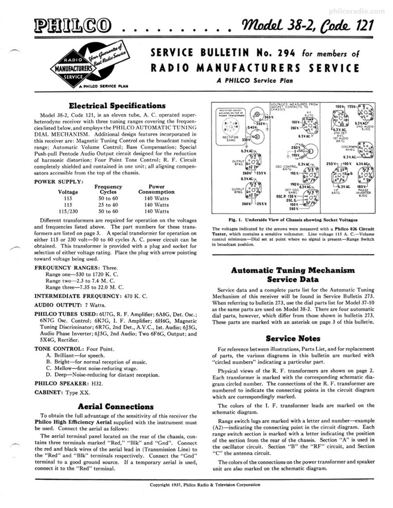
Fig. 1 shows the Voltage measurements taken from the bottom
of the sockets at each contact . In Fig. 2, the corre ct position of
the dial indicator , for proper adjustm ent of the compensators is
shown. Fig. 3, and 4, are the location of the I. F. and R. F.
compensators respectively .
The Model 37-610 code 121 receiver is used in cabinets type
B and J. In code 122 receiver, Type T cabinet is used. This
receiver differs from code 121, only in the rectifier socket mount-
ing and power transformer. The socket is placed adjacent to the
6F6G output tube and power transformer (Part No. 32-7626) is
used. Location of rectifier socket is shown in Figs. 1 and 6.
Electrical Specifications
Voltage Rating ) 115 Volts. A. C.
Frequency Rating: 50-60 and
For 25 to 40 cycle operation, use Power Transformer marked
with asterisk in parts list.
Power -Consumption: 60 Watts.
Type and Number of Tubes: 1 type 6A8G, Detector -Oscil-
lator; 1 type 6K7G, I. F.; 1 type 6Q7G; 2nd Detector, A. V. C.
and 1st audio ; 1type 6F6G, Output ;and 1type 5Y4G Rectifier.
®(§"
330"
r----------------1.,
: r------..T• !
6.3V~·AL
11.SV.
DCl.·OSC. or.~Qo
~
qov: 220v .
i ,..-----...... :
, \ 1 LOCAt}OMOf R~Cllfl[R SOCIS[T
l ,'·Po,.':.OP ; ! !!i..Ttooc121(,{~)"ccc,vcR,
! \,
\~}~:;~
~
◄
-··
-+-+'-+----'
! •,, H
L____---- ____________J
yoLTAG[SMEASURtOFAQtlTUOC
CONTACTS TO CHA$$1.S.
Fig 1-Tube Socket Voltages
Viewed from Underside of Chassis
l,.J17·A.C.
H 01(0
oa~.
q()lt ZlO~
The Voltages Indicated by Arrows were Measured with a PHIL CO 02S CIR-
CUIT TESTER which contains a 1000 ohm per volt Voltmet er. Range
Switch in Broadcast Position . 115 volt lifle.
Undistorted Output: 3 Watts.
Type Circuit: Superheterodyne with Pentode Output.
Intermediate Frequency: 470 K. C.
Tuning Ranges: 3. Range 1; 530 to 1720 Kilocycles.
Range 2; 2.3 to 7.4 Megacycles.
Range 3; 7.35 to 22 Megacycles .
Speaker Code: 121.- HS.
Speaker Code: 122.- S7.
POWER TRANSFORMER DATA
Lead No.
Shown Re-
on Sche- AC Volts Currents Circuit Color sistance
matic
1-2 120 -Pri. White 5ohms
3-4 5.0 2.0A Fil. Blue .1 ohms
Rectifier
High 145ohms
5-7 670 70 M.A . Voltage Yellow 155ohms
Sec.
6 - - .Center --
Tap of 5-i
8-9 6.7 2.lA Fil. Black .1 ohms
Copyright I936, Philco Radio & Televi sion Corporat ion
philcoradio.com

Page 2 PHILCO
Service Bulletin No. 249
lsr.I.F:TRANS.
@S EC.-470K .C:_;,.,,l-r----,
@ PRl.-470 K.C.
@2NO.l.f.TRANB.
PRl.-470K.C.
@SEC. -470K.C. \ CD~ <D
@ANT- ,.oHt
Fig. 2-Dial Calibration Fig. 3-Locations of I.F. Fig. 4-Locations of R.F .
Compensators
Top of Chassis Compensa tors
Underside of Chassis
Alignment of Compensators
The accurate adjustment of the various compensating conden-
sers is vital to the proper functioning of this receiver. There are
four compensating condense rs in the I. F. Circuit, four in the
Oscillator Circuit, and three in the Antenna Circ uit. Incorrect
adjustment will cause loss of sensitivit y, unsatisfactory tone, and
poor selectivity.
To accurately adjust this receiver, precision test equipment is
necessary . A signal generator such as the PHILCO MODEL 088
SIGNAL GENE RATOR , covering from 110 to 20000 K. C. is
recommend ed to adjust the compe nsators at the various fre-
quencies specified. A visual indication of the receiver output is
also necessary to obtain correct adjustment of th e compensators.
PHILCO MODEL 025 CIRCUIT TESTER contains a sensitive
output met er and is recommended for these adjustments.
Philco Fibre Wrench No. 3164 and Fibre Handle Screw-driver
No. 27-7059 complete the necessary equipment for these adjust-
ments . The locations of the various compensators are shown in
Figs. 3 and 4.
The following procedure must be observed in adjusting the
compensato rs:-
DIAL ADJUSTMENT-In order to adjust this receiver cor-
rectly, the dial must be aligned to track properly with the tuning
condenser. To do this, rotate the tuning ·condenser control to
the extreme counter-clockwise position (max imum capacity).
Loosen the set screw of dial hub, then turn dial until the glowing
indicator is cente red between the index lines of dial scale (see Fig.
2). Now tighten the dial hub set screw in this position.
OUTPUT METER-Th e 025 Output Mete r is connected to
the plate and cathode terminals of the (6F6G) tube. Adjust the
meter to use the (0-30) volt scale.
Before adjusting the compensators of each circuit, the signal
generator attenuator should be set to give approximately ¼
scale reading on output meter.
INTERMEDIATE FREQUENCY CIRCUIT
Frequency 470 K. C.
1 Connect the 088 signal generator output lead through a .1
mfd. condenser to the contro l grid of the 6A8G and the ground
connection of output lead to the chassis.
2 The tuning range switc h is set in position No. 1 (Broadcast).
Rotate the tuning condense r of receiver to the maximum capa-
city position (counter-clockwise), and adjust the signa l gener-
ator for 470 K. C.
3 Adjust compensators@ 2nd I. F . Sec.,@ 2nd I. F. Pri., @ 1st
I. F. Sec. and @ 1st I. F. Pri. for maximum reading on output
meter. RADIO FREQUENCY CIRCUIT
Tuning Range--7 .3 to 22.0 M. C.
1 Remove the signa l·generato r output lead from grid of 6A8G
tube ~nd connect it through a 0.1 mf. conde nser to terminal
No. 1 on aerial input panel, rear of chassis . Connect generator
ground lead to chassis. Terminals 2 and 3 of aerial input panel
must be connected with connector link provided on the panel.
2 Set tuning range switch in position No. 3. Turn signal gener-
ator and receiver dial to 18.0 M. C. and adjust compensators
@ osc., and ®a nt.for maximum output.
The adjustm ent of the antenna compensator on the high fre-
quency range causes a slight detuning of the oscillator circuit.
In order to overcome this detuning effect, connect a variable
conde nser of approximately 350 mmf., having a good vernier
drive, across the oscillator section of the tuning ,condenser.
Leaving the signal generator and receiver dials at 18.0 M.C.,
tune the added condenser so that the second harmonic of the
receiver oscillator will beat against the signal from the 088
signa l generator. The antenna compensator ® should then
be adj ust ed to give maximum output. Now remove the ex-
ternal condenser and turn compensator @) to ma>.i;:!•.•m ca-
pacity (clockwise) then without moving signal generator or
receiver tuning cond enser, back off compensator @ (counter-
clockwise ) until a second peak is reached on the output meter .
Note :-The first peak is caused by tuning to the image signal
and must be neglected.
Tuning Range: 2.3 to 7.4 Megacycles.
1 Turn range switch to position No. 2 (Police). Rotate signal
generator and receiv er dials to 7.0 M.C. Then adjust compen-
sato r @ for maximum output . Now turn signa l generator and
receiver dials to 6.0 M.C. and adjust compensator© for max-
imum reading on output meter.
Tuning Range : 530 to 1720 Kilocycles.
1 Set range switch in position No. 1 (standard broad cast). The
088 signa l indicator is set at 800 K. C. and the receiver dial at
1600 K. C.
(a) In adjusting the receiver at 1600 K. C., the second har-
monic of 800 K. C., to which the signal generator is tuned, is
used.
Now adjust compe nsator@ osc., 0 ant . for maximum output.
2 The low frequency end of the band is now tuned by turning
signa l generator and receiv er dials to 600 K. C. and adjust
compensator @ for maximum output. When compensato r @
osc. series is being adj usted , the tuning conde nser must be
rolled for maximum output. This is accomplished as follows :
First tune compensator @ for maximum output . Then vary
the tuning conden ser for maximum outp ut abo ut 600 K. C.
Now retune compensator @, and again vary the tuning con-
denser back and forth at 600 K. C. for maximum output. This
operation of first tuning the compensator, then the tuning con-
denser is continued until maximum outp ut is obtained at the
600 K. C. frequency.
3 After the low frequency (600 K. C.) end of range 1 is adjusted,
the 1600 K. C. end is re-adjusted, as given in Paragraph 1
above, to correct any variation that the low frequency series
compensator may have caused in the alignment of the high
frequency end.
4 Now turn signal generator and receiver dial to 1500 K . C. and
re-adjust compe nsato r 0 for maximum output.
philcoradio.com

Page 3
14
0
...
@ J\__'--2TAP
DSC. TRAIIS.
POLICE
PHILCO
Service Bulletin
/&ru_N_l~G
C
-
□
~~;N;f
-
;
.
~
l 10SC. TRANSJ
tru~o~o~_•sr
@)1.....4.l 1.6)' •.,. """W · @J2"0 IF. TRANS
7.\_"-' R[D+9 ~ G.RC.E.N OIODC PLAT[
OSt. TRAIIS. BROWN:8~ •·
~
SHORT WAVE: A.v.t
~~
@5,
GRC£11 C.SUD _
... .-.,>;>1::,. WHIT(
--- ==:::::::..::___PLAT[ BROWN
C -u ,t\tl1
c§,n:
~
c7 ca ~~o: ~a 09
C6 C1O 06 ,o' ,,,. ..., ,,. D1O
cs 05
~
~
11 011
◄::
I-
~
A9 ~B: Bl 89
A 5C::>-t..r, A10 B 6
B5 B10
A11 a, ,
A12 · B11 C4 12 04 o ---~ ;-,_-~, ..'J :I - "'
C 03 0 ~012
C2 C1 ~02 01
A2A1
~
. ~B12
~
B2 B1
) )
No. 249
-~~'@
----
)
philcoradio.com

Page 4 PHILCO
Service Bulletin No. 249
/LOCATIONorRE.CtSOCK£T\
\ COD£ IZZ RECEIVER./
Flit, 6-Base View of Chassis
Replacement Parts-Model 37-610
Schem. Description Part
No. No.
, AntennaTranaformer(Broadcast)........................ 32-2108
1 AntennaTran,former (Police)........... , .. .. .. .. .. .. .. . 32-2119
• AntennaTranaformer(Short-Wave)...................... 32-2109
Compenaator(Broadcast)... ..... . .. .... , . . .. .. . . .. .. .. . 31-6092
CompenaatorAnt. (Police)... .. .. .. . .. .. .. .. .. .. .. .. .. . Part of©
• CompenaatorAnt. (Short-Wave)....... .. .. ... . ..... ..... Part of©
TuningCondenser.. .......... ....................... ... 31-1821
Condenser(.05mfd. Tubular)......... .. . .. .. ........ ... 3<H020
• ElectrolyticCondenser16mfd.. . . .. .. . . .. .. . . .. .. .. .. .. . 30-2118
Resistor(10000ohm ½watt) .... •.... .................... 33-310339
@ Condenser(260mmfd.Mica) .. .... .... .... .. ............. 30-1032
0 OocillatorTransformer(Broadcast)......... . .. .. . . ... .. .. 32-2120
§
0 CompenaatorOoc. Series600K.C......... , ............... 31-6066
CompenaatorO.c. 1600K.C...................... ... .... 31-6002
CompenaatorO.c. 7.0 Meg.. ........ .............. .. ..... Part ofO
OscillatorTransformer(Police)......... . . ,. .. .. . . .. . . . . . 32-2121
0 Condenser(Semi-fixed1660mfd.)... ....... ,....... ... .. . 31-6096
0 OocillatorTransformer(S.W.). . ... . ...... .. ... . ....... . . 32-2110
0 Compenaator(Osc.18.0megacycles)........ .. .. , . . .. .. . . . Part of O
0 Condenser(Semi-fixed3500mfd.)............ , ., ... , ,.... 31-6097
@ Resistor(32000,½ watt) .. ...................... . .. , . .. . 33-332339
0 Resistor(51000,½watt) ............... ...... ...... , .... 33-361339
OA Condenser(.! mld. Tubular)....... .. ...... ... ......... 3<H170
0 Resistor(20000 ohm, ½ watt).. .. .. .. .. .. .. .. .. .. .. .. .. . 33-320439
0 1st I. F. Tranaformer..... .. ............................ 32-2100
0 Compenaatorht I. F. Transformer........... .'........... Part of O
0 Comrnaator let I. F. Transformer.. .. .. . .. .. .. . .. .. .. .. . Part of0
0 2nd . F. Transformer.. ...... ........... ........ ; . .. .. . 32-2102
0 Compensator2nd I. F. Transformer...................... Part ofO
0 Comr.;naator2nd I. F. Tranaformer... . ............. .. .. , Part ofO
0 Con enser(110mmfd. Mica)......... .. .......... .... ... 30-1031
0 Resistor(51000obm, ½watt) .............. .. ........ ... 33-351339
0 Condenser(110mmfd: Mica)........... ... ............. . 30-1031
§Resistor (490000ohm ½ watt)... .. ... .. .. .. .. .. .. .. .. .. . 33-449339
4 Condenaer(.01mfd. Tubular)........ .. .. ............. . . 30-4124
Resistor(I megohm½watt) .. ... ... , .. . . .. . 33-510339
0 Resistor(I megohm½ watt) .. . ... .. .. . . .. . . 33-510339
~
Conden,er(110mfd. Mica).. ............... .. 30-1031
0 Resistor(I megohm½ watt).... .. .. .. .. .. .. . .. .. .. .. 33-610339
0 Condenaer(0.1mfd. Tubular)... .. .. ... . .. . .. ... . 30-4122
0 Resistor(490000ohms,½ watt) .. .. .. .. .. .. . . .. .. .. .. 33-449339
@ Condenser(.015mfd. Tubular).... 3<H35S
0 Volume Control............. .. ............ . . .... ....... 33-5158
0 Resistor(51000,½ watt) . . .. .. . . . ................ .. ... 33-510339
0 Condenser(.008 mfd. Tubular). ...... .. .... ...... . . . 3<H112
0 Condenser(.015mfd. Tubular)............ . .... .. 30-4226
0 Resistor(1megohm½ watt).. .. .. . .. .. .. .. .. .. .. 33-510339
4-~Resistor(70000ohm ½ watt). .... .. .. . . .. . . .. .. . 33-370339
0 Output Transformer...... .. .. .. .. .. ... .. .. .. .. .. .. .. 32-7019
~
Voiet>Coiland Cone.. . . . . . . .. . . . 36-3157
t, Condenser( 03mfd. Tubular).... . ... .. ... .. ........... 3<H380
~ Condenser(.008mfd. Tubular)......................... . 3<H112
A Tone Controland ACSwitch........................... . 42-1182
0 ElectrolyticCondenaer(8 mfd.). ..... .. .. .. .. . .. . . .. . . .. . 30-2024
0 ResistorC-Bias.. ... .. .. ... . .. .. .. .. .. .. .. .. .. .. .. .. .. 33-3277
0 Field CoilAeoembly........ .... ...... .. ......... .. .... : 36-3039
3 ElectrolyticCondenser (12mfd.)................. . ... ... 30-2117
Resistor(9000ohm2 watt).. .. .. .. .. .. .. .. .. . .. .. .. .. .. . 33-290539
'"Code122, *'"Code-122,26cycleoperlltion.
Price
List
10.80
.65
.75
.60
3.60
.20
1.65
.20
.25
.65
.55
.60
.40
.40
.75
.50
.20
.20
.25
.20
uo
1.50
.20
.20
.20
.20
.25
.20
.20
.20
.20
.20
.20
.20
1.00
.20
.20
.20
.20
.20
.85
.80
.20
.20
.75
1.10
.20
2.75
1.20
.30
Schem . Description Part
No. No.
0 PowerTranaformer50-60cycle115volt•....... .. ......... 32-7583
PowerTranaformer26-40cycleI15volts...... . .. .. .. .. .. . 32-7684
•Power Tramformer 50-60cycle 115voltoCode 122.... .. .. . 32-7626
.. PowerTransformer26-40cycle115voltoCode 122......... 32-7627
0 Condenaer(TwinBakelite,.015-.016mfd.). .. .. .. . . .. .. . .. 3793DO
0 Pilot Lamp.. .. .. . .. .. .. .. .. .. .. .. .. .. .. .. .. .. .. .. .. .. . 34-2039
O WaveSwitchAntennaSection...... ...... ............... 42-1170
O WaveSwit-0hOoc. Section.. .............. ... . ,. .... .. ... 42-1172
I. F. WiringPanel. .. .. .. .. .. .. .. .. .. .. .. ... . .. .. .. .. .. . 38-7703
I. F. WiringPanel Spacer........... .... ......... ....... .28-4001
Ant. Panel................. ...... ...... .. .. .... .. ..... 38-7714
Price
List
14.25
Per C
.40
.11
1.10
1.10
.26
.25
Tube Socket7 prong.................... ...... .. ...... . 27-6057 .II
Tube Socket8 prong.................................. . 27-6058 .II
Tube SocketRectifier, Code 122..... .. ..... ... .......... 27-6053 .II
Tube Shield.. . ........................................ 28-2726 .JO
I. F. TransformerShield... .. .. .. .. .. .. .. ... . .. .. .. .. .. . 38-7763 .20
ACCable...... ....................................... L-2183 .40
SpeakerCable... .. . .. .. .. .. .. .. .. .. .. .. .. .. .. .. .. .. ... L-2181 .:,.,
GrommetMtg. Tuning_Condenser........ .. .. .. .. . .. .. .. . 27-4326 .02
GrommetMtg. R. F. Unit......... .. .. ........ ......... 27-4317 .04
Mtg. SleeveR. F. Unit..................... ......... ... 28-2257FA-3 .01
Mtg. ScrewR. F. Unit...... .... ........................ W-729FA-3 Per C .46
Mtg. WMherR. F. Unit............. .......... .. .. ..... 28-3927 .01
Pilot LampA1Bembly....... .. .. .. .. .. .. . .. .. .. .. .. ... . . 38-7706 .36
BracketElectrolyticCondenser... .. .. .. .. .. .. .. .. .. .. .. . 6440 .O&
BracketScrewElectrolyticCondenser.................... W-1446FA-3 Per O .40
Bracket Nut ElectrolyticCondenaer.. .. ... .... .. .... ..... W-96FA-3 Per C .30
ChassisMtg. Screw............... .'....... .. ........... W-1358A Per C 2.60
WaveSwitchIndexing Plate-6:Shaft..... .. ... .. ......... 42-1173Rev-E .60
Dial... .. ... .. .. . .. .. .. ... .. .. . .. . .. . .. .. .. 27-6203 .50
Dial Hub..... ............................... .... ..... 28-7187FA-3 .12
Dial Set Screw........................ . .. ... ........... W-1641 .02
Dial Clamp............. ... . ...... : .... . ............... 28-2837FA-3 .10
Dial ScreenAeoembly...... .. ............... .. ......... 38-7912 .10
DialGear................. .. ... . .. ... ..... ....... ..... 28-7185 .10
DriveGear........ 31-1884 .25
ScaleGuard .. .. . 27-8324 .02
Dial GearThr11StSpring.. .. . . .. . . . . .. . . . . .. . 28-8611 .01
Dial Gear C. Washer ... . 28-3904 .OJ
Dial Gear Thrust WMher.. . 28-3976 .30
Mask......... . . 27-6198 .80
Mask Washer........ .. . . .. . . .. . . . 27-8318 Per C .60
Mask Armand Link Assembly... .. .. . .. . ... . . . .... . . 31-1866 .35
Ma..k
Guide. 38-7844
Spring... .. .. .. .. . .. .. .. ... .. . .. .. .. .. .. 28-8624
Lena.. .. .. .. .. .. . . . . . .. ... .. ... .. . . . .. .. .. . . . 27-8310
Knob Tuning Control ........ . . .. . . .. 27-4330
Knob Vernier.. .... ...... . .. . . ... .. . . 27-4331
Knolr-Tone & Volume.... .. .. ... ... 27-4332
Knolr- WaveSwitch............ .... ..... .... ... .. . .... 27-4326
VolumeControlShaft........... .. ................... .. 28-6499
VolumeControlSpring.............. .. ................. 28-4117
te:~::ng .Cli_P·_-_-_::·.:·.::: :: :: :: :: :: :: :: :: :: :: :: :: :::: :
~~m
W.. her..... •. .. .. .. .. .. .. .. .. .. .. .. .. .. .. .. .. .. .. ... . . 4436
Nut ToneVolumeControls...... ..... .. ...... ........... W-684FA-3
Speaker87....... .... .. ............................... 36-1009
SpeakerHS............................ .. ........ .. ... 36-1220
Per C .60
.02
.10
.10
.10
.10
.10
Per C .40
.03
Per C .76
Per C 1.50
Per C 1.25
PHILCO
May, 1936 Parts and Service Division Printed In U. S. A
philcoradio.com
Other manuals for 121
8
This manual suits for next models
2
Other Philco Radio manuals