manuals.online logo
Brands
  1. Home
  2. •
  3. Brands
  4. •
  5. Philco
  6. •
  7. Radio
  8. •
  9. Philco 37-60 User manual

Philco 37-60 User manual

-
• • • • • • • • • • • • • • Wlorkl 37-60
Special Date for Members of
RADIOMANUFACTURERSSERVICESERVICE BULLETIN
No. 245
A PHILCO SERVICE PLAN
Model 37-60
General Description
Model 37-60 is a 5 tube superheterodyne receiver for operation
on alternating current and has two tuning ranges, covering
Standard Broadcast and American short-wave reception up to 7
megacycles. The new Philco High Efficiency self-centering glass
tubes are used.
The circuit incorporates the Philco Aerial Tuning System-
controlled by the range switch-which provides maximum sensi-
tivity and noise reduction when used with the Philco All Wave
Aerial.
The red and black leads of the All Wave Aerial "transmission
line" are connected to terminals 1 and 2 respectively , of the
terminal pane l provided at the rear of the chassis. Connect the
jumper of the terminal panel across terminals 3 and 4.
If a temporary aerial is used, the jumper should be across
terminal 2 and 3. The aerial connects to terminal 1 and the
ground to terminals 3. A good ground connection is required in
all installations. CONSTRUCTION
The chassis is constructed in three basic assembly units.
The Radio Frequency unit contains a 6A8G tube which func-
tions as a Detector-Oscillator, tuning condenser, antenna and
oscillator coils for each tuning range, selector switch-compen-
sating condensers for all coils and other parts necessary for the
associated circuits. The unit is separately mounted on rubber
grommets, cushioning it from the main chassis.
The Intermediate Frequency unit, mounted on the right-hand
side of the chassis (facing the front) consists of the Intermediate
Frequency coils compensating condensers, a 6K7G tube for I. F'
Amplifier stage, and a 6Q7G tube as the second detector -
automatic volume control and first audio stage.
All voltag es suppli ed to the I. F. and R. F. units are furnished
from a terminal strip mounted in this unit.
The Power Pack and audio output circuits, together with the
required Voltage dividers and filter condensers are mounted in
the power unit. All high Voltage A. C. Wiring is housed in the
power transformer assembly which includes the rectifier socket.
Although unit construction has changed the appearance of
this model, the service bulletin will be of great assistance in
checking through all stages of the receiver. The Wiring Diagram,
as usual, is numbered, indicating all important parts. These
numbers correspond with the parts layout shown in Fig. 6. In
addition, the range switch wafers are shown on the schematic
diagram. The contacts on each wafer are lettered and numbered
to indicate their connection points in the schematic diagram,
which are also lettered and numbered. The physical drawings of
each coil used in the receiver are also shown on schematic diagram
Fig. 5. The connections of these coils are numbered on the coil
itself and on the -schematic diagram.
Fig. 1 shows the Voltage measurements taken from the bottom
of the ·socket at each contact. In Fig. 2, the correct position of
the dial indicator, for proper adjustment of the compensators is
shown. Figs. 3 and 4, are the location of the I. F. and R. F.
compensators respectively.
This Receiver is supplied in two models, type B and type F.
These instructions , however, are used for both types.
Electrical Specifications
Voltage Rating ) 115 Volts . A. C.
Frequency Rating: 50-60 Cycle.
For 25-40 cycle operation use Power Transformer, marked with
asterisks in Parts List.
Power Consumption: 60 Watts.
Type and Number of Philco Tubes: 1 type 6A8G First
Detector-oscillator; 1 type 6K7G I. F . Amplifier; 1 type 6Q7G
®@J'
R[tTln[R TVS[ P10UNTCOON )130V.
TOP or POW[R TR.MS. .
f R[CTlflER :
! 5Y4G
:
~
C~i'il
:___________________________, VOLTAGES H(ASUR[D FROM TUB[
CONTACTS TO CHASSIS.
Fig. I-Socket Voltages
Viewed from Underside of Chassis
2No.0ET.
l:n:AUOIO
175V. E,Q1G
Measurements taken with Philco Model 025 Circuit Tester which contains a
1000 ohm per volt voltmet er. Line voltage, 115- Wave Switch in Broadca st
Position. Dial turned to 600 KC.
2nd Detector, A. V. C., and 1st Audio; 1 type 6F6G Pentode
Output and 1 type 5Y4G, Rectifier.
Speaker: S7.
Type of Circuit: Superheterodyne with Pentode Power Output.
Intermediate Frequency: 470 K. C.
Undistorted Power Output: 3 Watts.
Tuning Ranges: Two-(1): 530 to 1720 K.C., (2): 2.3 to 7.4 M.C.
POWER TRANSFORMER DATA
Lead No.
Shown A.C. Current Circuit Color Resist-
on Sche- Volts ance
matic
1-2 120 -Primary White 50ohms
High 145 ohms
5-7 670 70 M.A . Voltage Yellow 155 ohms
Sec.
3-4 5.0 2.0 A Fil. Blue .1ohms
Rect .
8-9 6.7 2.1 A Fil. Black .1ohms
Center Yellow
6 ·- -Tap of Green Tr -
5-7
Copyright 1936, Philc o Radi o ·& Television Corporation
philcoradio.com
Page Z PHILCO
Service Bulletin No. 245
lnl,F;TRANS,
(19SEC,.-470K.c.;--,--,,.__--,
@PRl.·470K.C.I 0 0
G)OSC.lM.C.
@
ooo
0 0
0 0
$7 @D~~~C
(@SCREW·OSC.1600l<.C.)
\@ NUT· OSC.
600K.C.
__ I @ANT.
1500 K.C.
Fig. 2-Dial Calibration Fig. 3-Locations of Fig. 4-Locations of
I. F. Compensators Top of Chassis R. F. Compensators Underside of
Chassis
Adjustment of Compensators
The accurate adjustment of the various compensating con-
densers is vital to the proper functioning of this receiver. There
are four compensating condensers in the I. F. Circuit, three in the
Oscillator Circuit, and two in the Antenna Circuit . Incorrect
adjustment will cause loss of sensitivity, unsatisfactory tone,
and poor selectivity.
To accurately adjust this receiver, precision test equipment is
necessary. A signal generator such as the PHILCO MODEL 088
SIGNAL GENERATOR, covering from 110 to 20,000 K. C. is
recommended to adjust the compensators at the various fre-
quencies specified. A visual indication of the receiver output is
also necessary to obtain correct adjustment of the compensators.
PHILCO MODEL 025 CIRCUIT TESTER contains a very
sensitive output meter and is recommended for these adjustments.
Philco Fibre Wrench No. 3164 and Fibre Handle Screw-driver
No. 27-7059 complete the necessary equipment for these adjust-
ments. The locations of the various compensators are shown in
Figs. 3 and 4.
The following procedure must be observed in adjusting the
com pensa tors:
DIAL ADJUSTMENT-The Tuning condenser is set at the
maximum capacity position, by turning the tuning knob counter-
clockwise. Loosen the set screw of dial hub and set dial, (see
Fig. 2) with Glowing Indicator centered between the index lines
at the low frequency end of scale.
OUTPUT METER-The Output Meter is attached to the
Plate and Cathode terminals of the (6F6G tube) and adjusted to
use the (0-30) volt scale. When adjusting each circuit, care
should be taken to have the signal generator attenuator set to
give approximately ¼ scale reading on output meter.
INTERMEDIATE FREQUENCY CIRCUIT
1 Turn wave band ,iwitch to Range 1. Rotate the tuning control
to approximately 600 K. C. Connect the 088 Signal Gener-
ator output lead through a .1 mftl. condenser to the grid of the
6A8G tube, and the ground lead of Signal Generator to the
chassis.
2 Set Signal Geverator indicator for 470 K. C., adjust attenuator
for approximately ¼ scale reading on output meter. Then
adjust compensators @a 2nd I. F. Sec., @ 2nd I. F. Pri ., @a
1st I. F. Sec., @ 1st I. F. Pri., for maximum reading on output
meter.
RADIO FREQUENCY CIRCUIT-Range 2: 2.3 to 7.4 M. C.
1 Turn Range switch to Range 2. Remove signal generator
output lead from the grid of 6A8G tube .
2 Attach signal generator output lead through a 0.1 mfd. con-
denser to the ANT. TERMINAL No . 1, on aerial panel, and
the generator ground to chassis. Connect TERMINAL
No. 2, to GROUND TERMINAL No. 3, with connector link
provided on the panel.
3 Set Signal Generator and receiver dials for 7.0 M. C. Now
adjust compensator (i) for maximum reading on output meter.
Then turn Signal Generator and Receiver to 6.0 M. C., and
adjust compensator ®a for maximum output.
RANGE 1: 530 to 1720 K. C.
1 Turn range switch to Range 1. Turn the Receiver dial to 1600
K. C. Then adjust compensators ® and ® for maximum
reading on output meter.
The 088 Signal Generator dial is set at 800 K. C. and the second
harmonic of this frequency (1600 K. C.) is used in making the
above adjustment. ·
2 The low frequency end of the band is now tuned by t_urn\ng
Signal Generator and Receiver dials to 600 K. C. and adiustmg
compensator ® a-see note (a) below-for maximum output.
(a) When compensator @a osc. series is being adjusted, the
Tuning Condenser must be rolled for maximum output.
This is accomplished as follows : First tune compensator ®a
for maximum output. Then vary the Tuning Condenser
for maximum output at 600 K. C. Now retune Compen-
sator @a, and again vary the tuning condense_r back 3;nd
forth about 600 K. C., for maximum output. This operat10n
of first tuning the Compensator, then the. Tunin~ Con-
denser is continued until maximum output 1s obtained at
the 600 K. C. frequency.
3 Set the Signal Generator and Receiver dials for 1600 K. C.
and re-adjust Compensator® for maximum output. Then tur~
the dials to 1500 K. C. and re-adjust compensator® for maxi-
mum reading on output meter.
--~
philcoradio.com
Page 3
~
a,, ' 1 o
~
I
0.11' •2
A1U.
A5 " ,.,.,1/
r,:;"\ ANT. TRANS.
\!;I POLICE.
3/ ~2-TAP
CD
ANT. TRAMS.
&IIOADCAST
5
3\ '-2-TAP
r,;"\ ANT. TRANS.
\6/ POLIU
2·TAP
In\ OSC. TRANS.
\!/IIROADCAH
3 2-TAP
t,;;\OSC . TRANS.
'l!V POLICE.
B
AIO
A_LJ
I
I
I
I
1~
83
BB
BIi
0
I087 /
,~ ..®
POLICE. ·
PHILCO
Service Bulletin
@@
r~
f~
85 t,.,
0 88 ef 116,..f.
cw'"'¥
M ..
... ..
o_xBl2 f m DIRtCTION or 47
BIi
~
i
~
·
~
~
f? ROTATION FRQPI REAR
~
.-Vo.- ~w1n11 .
....,·:. =D !®CI""'1
I T .01s~i. .,. , I;:
I.F;470 K.~~;~-,,..a..;:::;.;;..;;.::·.;;.;.;.;=
INDICATE POSITION Of SWITCH S[CTIONS fR0"1 REAR BLACK
OF CHASSIS. :-SOLID ,AA.CA INDICATES "EAR OF SWITCH WAFC:R. _
~AIO
:- SHADU> AA.CA INDICATCS FRONT or SWITCH WAFLR. '=
:- ALL SWITCHC.S SHOWN IN B"OADCAST POS tTION.
Fig. 5- Schematic Diagram-Model 37-60
--
--
_,-
p
12~f.
~
8_.J.
No. Z45
IGR[E:N
~
-~Ii~
~1®~
"'I-
.. l:
-
~
:,:
1:
J;.lli~
~
0)0I:1
~
- 10
z: --
~
----
~~@
..._.............'"' .
--
GREEN
(i,f\10
WIIITC·PL.ATC
REO
·
♦
B
@ In. 1.F.TRANS.
Rt:O_·H!,
WHIT£.
PL,.Tt
6RCEN
0100£ PLAT[
BROWN
DIODE RtS.
®ZND . l.r TRANS.
philcoradio.com
Page4
6 F6 CHUB
OUTPUT
PHILCO
Service Bulletin
6 K7GTUBE
I. F.
No. Z45
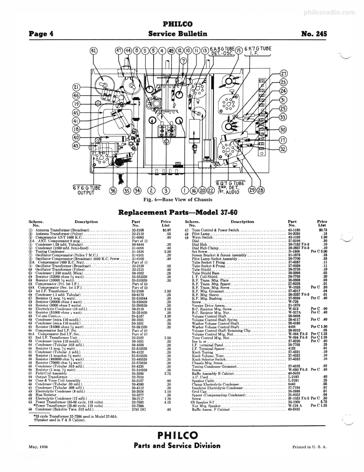
Fig. 6-Base View of Chassis
Replacement Parts-Model 37-60
Schem. Description Par,t
No. No.
(D Antenna Transformer (Broadcast) ............... . . . •.... . 32-2108
© Antenna Transformer (Police) .................. .. ....... 32-2119
© Compensator ANT 1600 K.C .......... , . ... ... . .. . . ..... 31-6093
©A ANT . Compensator 6 meg..... . .. .... .... .. ........ Part of©
I
Condenser (.05 mfd. Tubular}. . . .. . . • . . . . . • . . 30-4444
Condenser (1650 mfd . Semi-fixed) . . . 31-6096
Tuning Condenser .. . . . . . 31-1826
Oscillator Compensator (Police 7 M.C.) . . . 31-6101
® Oscillator Compensator (Broadcast) 1600 K.C. Screw. . . 31-6100
®A Compensator (600 K.C. Nut)........... . ..... Part of ®
® Oscillator Transformer (Broadcast)... 32-2120
@ Oscillator Trarusformer (Police).. ........ . . . . . . . . ... . . 32-2121
0 Condenser (.250 mmfd. Mica) ........................... 30-1032
0 Resistor (32000 ohms½ watt) .................. .... .... , 33-332339
0 Resistor (10000 ½ watt) ............... .. . . ...... .. ..... 33-310339
0 Compensator (Pri. 1st I.F.) ......... ...... ...... .... .... . Part of @
OA Compensator (Sec. !st I.F .)...... .. . Part of@
@ !st 1.F. Transformer ........ .. . . .. .. .. . .. •. .• .. .. .. 32-2100
0 Condenser (.1 mfd. Tubular). .. . . . .. .• .. , . .. . . . •. ... 30-4170
@ Resistor (I meg. ½watt).... . .• .. . . . ..• .... 33-510344
0 Resistor (20000 ohms I watt) 33-320439
0 Resisto r (9000 ohms 2 watts) .... . . . . . 33-290539
o· Electroly\ic Condense r (I 6 mfJ.).. .. . .. .. .. .. .. .. .. .. .. . 30-2118
0 Resistor (51000 ohms, watt) ......... . , . •. . .•.. . . , .. 33-351439
0 VolJmeContru1 . ...... 33-4157
0 Condenser (mica 110 mmfd.)............. .... .• .. .. .. 30-1031
0 Condenser (mica 110 mmfd.).... .. .. .. .. . . .. .. .. .. .. 30-1031
~~
Resistor (51000ohms½ watt) 33-351339
0 Compensator 2nd 1.F. Pri..... Part of ~j)
OA Compensator 2nd 1.F. Sec.. . . • . . . . . . . . • Part of~ ~
~j) 2nd 1.F. Transform er Unit .. .. .. .. .. . .. ...... . .. 32-2102
0 Condenser (m ica 110 mmfd.).. . 30-1031
f~ Condenser (Tubular .015 mfd.). 30-4358
0 Resistor (I meg. ½watt) .... ,. . .. .. .. .. .. .. .. .. .. .. 33-510339
0 Condenser (Tubular.) mfd.)... 30-4122
0 Resistor (I megohm ½watt)... 33-510339
0 Resistor (490000 ohm ½ watt). .. . . . . . . . . •. . . . . 33-449339
0 Resistor (70000 ohm ½ watt).. .. . .. .. • .. .. .. .. .. .. .. 33-370339
0 Condenser (Tubular .015 mfd.) ..... . , ..... . . . .. .. 30-4226
0 Resistor (I meg. ½watt.).. 33-510339
~j) Field CoiIAssembly. . . ......... , . , 36-3039
0 Output Transformer ........ .. . .. .. .. . . .. .. . 32-7019
0 Cone & Voice Coil Assembly. . . . . . . . . . . . . . . . . . 36-3157
@ Condenser (Tubular .03 mfd.).. . . . . . . . . . . . . . . 30-4380
@ Condenser (Tubular .008 mfd.). .. .. .. . . . . .. .. 30-4112
@ Electrolytic Condenser (8 mfd.) 30-2024
@ Bias Resistor... .. .. .. .. .. .. .. . 33-3277
@ Electrolytic Condenser (12 mfd.) .. .. .. . . . . 30-2117
@ Power Transformer (50-60 cycle, I 15 volts). 32-7583
*Power Transform er (25-40 cycle, I15 volts). 32-7584
@ Condenser (Bakelite Twin .015 mfd.) .... . . 3793 DG
*25 cycle Transformer 32-7584 used in Model 37-60A.
fSpeaker used in F & B Cab inet.
Price
List
so.so
.65
.40
.20
.40
3.00
.20
.40
.65
.40
.25
.20
.20
1.50
.25
.20
.20
.30
1.65
.20
1.00
.20
.20
.20
1.50
.20
.20
.20
.20
.20
.20
.20
.20
.20
2.75
.80
.20
.20
1.10
.20
1.20
4.25
.40
Schem. Description Part Price
No . No. List
@ Tone Control & Power Switch ... . . , . . . .. . . 42-1180 $0.75
@ Pilot Lamp ..... .............. .... . .. , .. .. .. •. .. .. .. .. . 34-2039 .15
@ Wave Switch . .................. .. ......... ....... ..... 42-1195 1.50
Dial.. .. . .. .. .. .. .. .. .. .. .. .. .. .. .. .. .. •.. . .. .. .. .. .. . 27-5196 .30
Dial Hub .............................. . ... ........ ... 28-7152 FA-3 .10
Dial Hub Clamp ................ .. ...... .. .... 28-2837 FA-3 .10
Set Screw ....... ....... ............. . .... ...... ....... N-1506 Per C 2.00
Screen Bracket & Screen Assembly ......... , . •.... .. •.... 31-1878 .25
Pilot Lamp Socket Assembly ........... .. ... . .. ......... 38-7706 .35
Tube Socket 7 Prong .................. .. . . ...... .. ..... 27-6057 .II
:J:~l:;~i:f:,•t8. Pron :::·.::::: :::: :: :: :::: : : :::: .........
~t~~g
:JA
Tube Shield Base ............. .. .. . .......... ....... ... 28-3898 .03
I. F. Coil Shield ................... . . ...... .. .. .... .. ... 38-7763 .20
R.F. Trans . Mtg . Plate .. ....... ......... . .............. 28-3808 .02
R.F. Trans. Mtg. Spacer .... .. ...... . ... .. .. .... ....... 27-8228 .01
R.F. Trans . Mtg. Screw ............. . ......... . ......... W-1635 Per C .30
R.F. Mt g. Grommet.. .............. . ................... 27-4317 .04
R.F. Mt g. Sleeve ......................... .. ........... 28-2257 FA-3 .01
R.F. Mtg. Bushing .... . ...... .. .. . .. . ... .......... .... 27-8339 PerC .40
Screw ...... .................... .. ................ .. W-729
Vernier Drive Assem.... ... .. .. .. .. .. .. .. .. .• .. .. .. .. .. 31-1879
B.C. Resistor Mtg. Screw.......... . ... ....... . ........ W-512
B.C.ResistorMt~.Nut.. . . . . . . ... . . . . ... . ...... W-317A
Volume Control Shaft. ........ ..... . .... .. . ....... .. ... 28-6498
Volume Control Shaft Sprin~ .. .... .... ..... . . ........ .. , 28-4117
Washer Volume Control Shaft ............... . . ......... 28-4186
WBRherVolume Control Shaft ............... . .. .... ..... 4436
Volume Control Shaft Retaining Clip......... .. 28-8610
Volume Control Mtg. Nut. ................ , .. ..... W-684FA-3
Tone Control Mtg. Nut ................. .. . ... ......... W-684FA-3
Ins, lu or . .. .......... . , . 27-8320
I.F. 'i'erminal Panel... .. . . . . . . .. .. .. .. .. .. . . . . .. 38-7703
I.F. Terminal Spacer.. . . . ... .... .. .. .. .. .. . . ......... 4122
Knob Tuning........ .. .. .. .. .. .... .. .. ..... 27-4321
Knob Volume, Tone. . . , . . . . • . . . 27-4332
Knob Selector Switch . . . . . • . . . . . . . . 27-4332
PerC .90
Per C .40
Per C .40
Per C 1.50
.03
Per C 1.25
Per C 1.25
Per C .40
.25
.01
.10
.10
.10
Chassis Mtg. Screw . . .. . ... . . .. . . •.
Tuning Condenser Grommet .. . . . . •. . . ... .
Screw.... ................. .
Baffle Assembly B Cabinet ... .
27-4325 .02
W-650 FA-3 Per C .40
40-5935
A.C. Cord ...... .
Speaker Cable..... .... ..... .. L-218-1 .40
.. .. .. .. .. .. .. . L-2181 .25
Clamp Electrolvtic Condenser ...... . . .
Insulator Electrolytic Condenser ... . .... ........ .. 6440 .05
27-7194 .01
Grid Cap 38-3888 .01
Spacer (Compensating Condenser) ...... .. .. .. .. ., .•.. 29-6032 .04
W-1653 FA-3 Per C .30
Screw......... .
tB Speaker S-7
Nut Mtg . Speake r ......
Baffle Assem. F Cahinet .
.... 36-1009 5.75
.. ... ..... .... .. .. ... W-124 A Per C 1.35
......... "' ..... 40-5933
PHILCO
May, 1936 Parts and Service Division Printed in U.S. A.
philcoradio.com

Other Philco Radio manuals

Philco PHOTOFACT 49-1150 User manual

Philco

Philco PHOTOFACT 49-1150 User manual

Philco 29 User manual

Philco

Philco 29 User manual

Philco 118 User manual

Philco

Philco 118 User manual

Philco 121 User manual

Philco

Philco 121 User manual

Philco 39-55 User manual

Philco

Philco 39-55 User manual

Philco 650 User manual

Philco

Philco 650 User manual

Philco 144 User manual

Philco

Philco 144 User manual

Philco 643 User manual

Philco

Philco 643 User manual

Philco 37-620 User manual

Philco

Philco 37-620 User manual

Philco 28 User manual

Philco

Philco 28 User manual

Philco 121 User manual

Philco

Philco 121 User manual

Philco 37-670 User manual

Philco

Philco 37-670 User manual

Philco 37-116 User manual

Philco

Philco 37-116 User manual

Philco 121 User manual

Philco

Philco 121 User manual

Philco 96 User manual

Philco

Philco 96 User manual

Philco 623 User manual

Philco

Philco 623 User manual

Philco D-592 User manual

Philco

Philco D-592 User manual

Philco 16 Reference manual

Philco

Philco 16 Reference manual

Philco 116 User manual

Philco

Philco 116 User manual

Philco 200 User manual

Philco

Philco 200 User manual

Philco 80 User manual

Philco

Philco 80 User manual

Philco 37-650 User manual

Philco

Philco 37-650 User manual

Philco 37-630 User manual

Philco

Philco 37-630 User manual

Philco 121 User manual

Philco

Philco 121 User manual

Popular Radio manuals by other brands

Sirius XM RAdio XMp3i quick start guide

Sirius XM RAdio

Sirius XM RAdio XMp3i quick start guide

Roadstar HRA-1200W instruction manual

Roadstar

Roadstar HRA-1200W instruction manual

Panasonic RF-D10 operating instructions

Panasonic

Panasonic RF-D10 operating instructions

Sony ICF-18 operating instructions

Sony

Sony ICF-18 operating instructions

Sangean PR-D1 Service manual

Sangean

Sangean PR-D1 Service manual

Tait TOP Operation and service manual

Tait

Tait TOP Operation and service manual

Tesco DR1502B user guide

Tesco

Tesco DR1502B user guide

Ocean Digital WR-210CB user manual

Ocean Digital

Ocean Digital WR-210CB user manual

Goodmans GSR1885DAB user guide

Goodmans

Goodmans GSR1885DAB user guide

Conrad 752001 operating instructions

Conrad

Conrad 752001 operating instructions

SOUNDMASTER DAB270 manual

SOUNDMASTER

SOUNDMASTER DAB270 manual

National Instruments USRP-2920 Getting started guide

National Instruments

National Instruments USRP-2920 Getting started guide

iGear VINTAGE VIBES iG-1112 manual

iGear

iGear VINTAGE VIBES iG-1112 manual

Grace Digital SiriusXM Sound Station quick start guide

Grace Digital

Grace Digital SiriusXM Sound Station quick start guide

AnyTone AT-500M instruction manual

AnyTone

AnyTone AT-500M instruction manual

Myryad Car Satellite Radio System user guide

Myryad

Myryad Car Satellite Radio System user guide

PRESIDENT WALKER owner's manual

PRESIDENT

PRESIDENT WALKER owner's manual

Inovonics INOmini 662 SiteStreamer Installation & user guide

Inovonics

Inovonics INOmini 662 SiteStreamer Installation & user guide

manuals.online logo
manuals.online logoBrands
  • About & Mission
  • Contact us
  • Privacy Policy
  • Terms and Conditions

Copyright 2025 Manuals.Online. All Rights Reserved.