manuals.online logo
Brands
  1. Home
  2. •
  3. Brands
  4. •
  5. Philco
  6. •
  7. Radio
  8. •
  9. Philco 121 User manual

Philco 121 User manual

• • • • • • • • ?rb,dtJ.IA37-10an.ti37-11
FOR MEMBERS OF
RADIOMANUFACTURERSSERVICE
A PHILCO SERVICE PLAN
SERVICE BULLETIN
"•-168
Models 37 .•10 and 37-11 Code IZI
Electrical Specifications
TYPE CIRCUIT: Superheterodyne, with Automatic (Dial) Tuning,
and Magnetic Tuning control on the broadcast range .
Both receivers use a push-pull pentode audio output circuit.
The 37-11 receiver however, uses a 6J5G, second <letector and
6K5G 1st audio tuhe .
DIAL MECHANISM: Philco Automatic Dial Tuning- Systc111.
POWER SUPPLY:
Voltage Frequency Cycles Consumption
37-10 37-11
115 50 tu 60 120watts
115 25to40 125watts
INTERMEDIATE FREQUENCY: 470 K. C.
125watts
130 watts
UNDISTORTED OUTPUT: 37-10, 5 watts. 37-11, 7 watts .
PHILCO TUBES USED: 37-10-Nine . Two 6K7G; one 6A8G ;
one 6N7G; one 6H6G; one 6Q7G; two 6F6G, and one 5Y4G.
37-11-Ten. Two 6K7G; one 6A8G; one 6N7G ; one 6H6G;
one 6K5G; one 6J5G; two 6F6G, and one 5Y4G .
TUNING RANGES: Three.
Range 1-530 to 1720 K. C.
Range 2-2 .3 to 7.4 M. C.
Range 3-7.35 to 22 M. C.
TONE CONTROL: 37-10-3 Positions. 37-11-4 Positions.
SPEAKER: H-30.
Aerial Connections
To obtain the full advantage of the sensitivity of this receiver, the
Philco High Efficiency Aerial supplied with the receiver must be used.
The connections for the aerial are as follows :
The red and black leads of the High-Efficiency Aerial "transmission
line" are connected to terminals 1 and 2 respectively, of the terminal
_panel provided on the rear of the chassis. Connect the jumper on
the terminal panel across terminals 3 and 4.
If a temporary aerial is used, the jumper should be across terminals
2 and 3. The aerial connects to terminal 1 and the ground lead to
terminal 3. A good ground connection is desirable in all installations.
Dial Calibration
In order to adjust this receiver correctly the dial must be aligned
to track properly with the tuning condenser. To do this proceed as
follows:
1. Loosen the shaft coupling set screws. Then turn the tuning
condenser fully closed and the dial to the first index line. Now
tighten the shaft coupling set screws, and rotate the dial until the
520 K.C . mark is midway between the index line and the glowing
beam indicator.
l. With condenser in this position loosen the set screws of the
shaft coupling on the tuning condenser .
3. Then turn the tuning dial ·until the glowing beam indicator is
centered on the index line.
_NOTE: Be careful when turning the dial th at the position of the
'-..../ tuning condenser is not disturbed.
4. Now tighten the shaft coupling set screws .
;··········~:~:~.;:~·········1
i
~y~~
i
: ,' ' :
·,;® ()f~?·)®i
,.. ,•
'
. '
L•••••••••••••••••••••·•••••.J
All VOlTAGCSMEASURED
l'IIOM SOCIIETCONTACTS249!T
TD CHASSII. 6J::>G
IN MOOIL
37-11
Fig. 1. Socket Voltages 37-10-11
Underside of Chassis View
The voltages indicated by arrows were measured with a Philco 025 Circuit Teater
which contains a voltmeter having a resistance of 1000 ohms per volt . Volume
Control at minimum, range switch in broadcast position, line voltage 115 A. .C.
NOTE
Models 37-10 and 37-11 are similar in circuit design, with the
exception that the 6Q7G tube, 2nd Det. 1st Audio in the 37-10 is
replaced with a 6J5G as a diode detector and a 6K5G tube for 1st
audio stage in the Model 37-11. The schematic diagram Fig. 3 shows
the complete circuit of the 37-11 receiver, also the 6Q7G, 2nd Det.
1st Audio circuit of the 37-10. The parts of these two chasses are
the same with the exception of condenser (81A) in the tone control
circuit and the tone controls. In Model 37-10 the condenser is
Part No. 3615-SU .05 mfd., and in the 37-11 it is Part No. 3615-YU
.05 mfd., .03 mfd.
Resistor locations in both receiver power units are slightly different
as will be noted in Figs . 5 and 7.
g
..
s §l
ni
2n
~
..
~
..
~
"
8
~
Fig. 2. Dial Calibration Fta. 3. Speaker
Copyright 1936 Philco Radio and Television Corporation
philcoradio.com
Page2 PHILCO Service Balletin
·•-t:1111
~
86 ~. ,..../
1~.F·t~
BROADCAST POLICE SHT ._.V£
ANTENNA TRANS .
·i ·t?
~I~
BROADCAST POLICE SHT \JrAVE
R.f . TRANSFORM(RS <
0
0
0
8 I 4 II NOTE.FIL . @ 'v' WMJT[1 , ..
~
@ ®---A-LL SWITCHESSHOWNIN POSITIONNO.I !lROIIDCA
5 6 • 211v J I ~,s4"~,,fJ_ I"':?'[
''~I 3 SHADED AREA INDICATES FRONT Of SWITCH WAFER P ILACK
1 SOLIDAREA INDICATES REAROf SWITCH WAFER
~
POLICE s ...,.VE LETTERS INOICATEPOSrTION f'ROM REAR Of CHASSIS .
OSC. TRANSF°ORMERS ~~oe eg
'1 POL ICE ,•. 11 8'(2•. Ill
•3 ~MT.WA~ "t BDCAST • 11 ~.i!
~
~~~
\ ~- 0
OIREC.TION Of ROT.TION • Al A1 14' ,
~
FROM REAR or ,w,rcM. ANTENNA B
_A..--_
,.•0
"
.!!L a
...IL
IOl'f
I:
Fig 4. Schematic Diagram
Models 37-10, 37-11
(
~
...
IF.=470KC.
<
C,
C
O•
.
<
O>
No. 218
,, ·H
O,I' El' ,JF ii
WIRING OF M00t:LJ7 · IO2i'0 .OE1
15T AUDIO C.IRC.UIT
2No.LF. TIIAN4.
@
POWERTRANS.RES
t,.: ,..uu. Tll M0Dll 3110 MODEL31·11
..EAi. No :,
1 - ' '2. 0..n. 1.6.n.
:!- 4 LE.S~ .1 .n LESS .1 .n.
5 · E·1 50.:.. lb OA 64AJ66.n.
8-9 L[ 5~ .In LESS .l.t\.
( - I
philcoradio.com
Page3
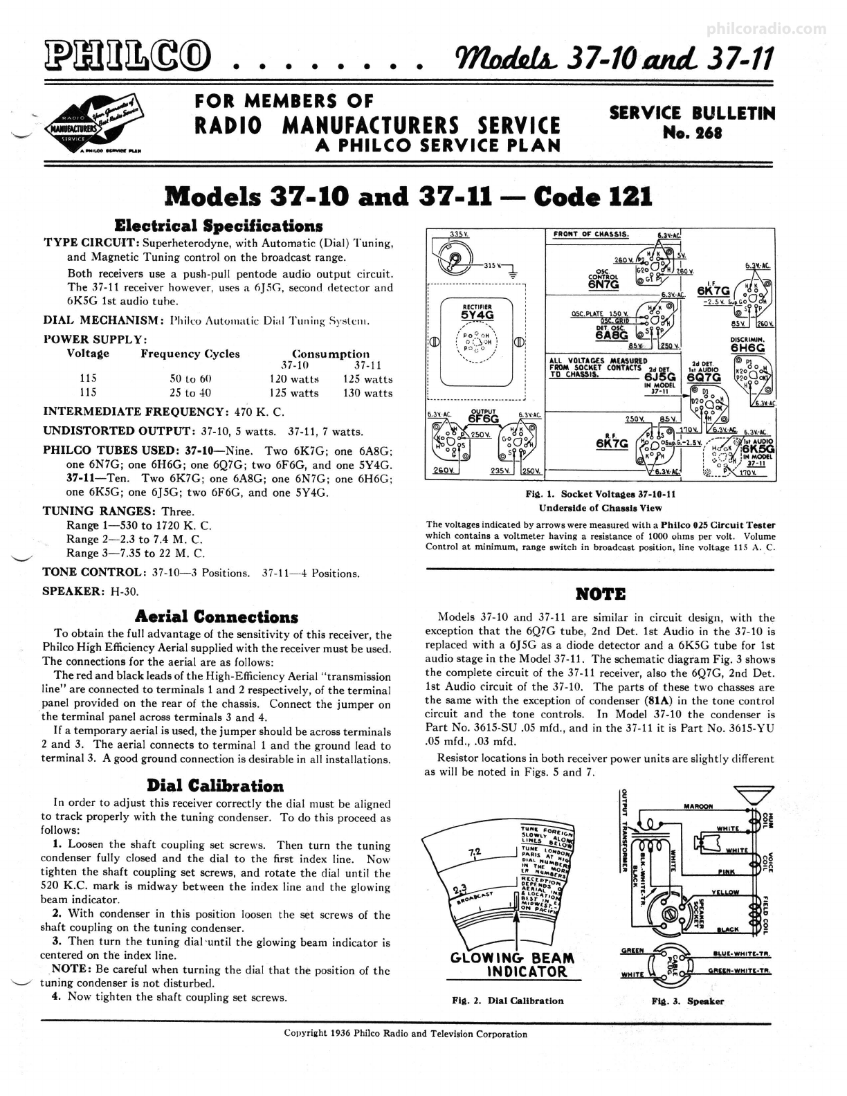
Fill. 5. 37-11 Power Unit Base View
Schem. Part
No. o-iption No.
1 Antenna Transformer (Range 1). 32-2108
2 Compensator (Three section) .... . . . . . 31-6092
3 Antenna Transformer (Range 2) . . . .. . 32-2119
4 Antenns Transformer (Range 3) .. ... . 32-2109
5 Condenser (.05 mfd. tubular) .. . ...... 3~020
6 Resistor (51,000 ohms, ½ watt). . . . . . 33-351339
7 R. F. Transformer (Range 3).. .. . . . . . 32-2126
8 Condenser (.05 mfd. tubular). . . . . . . . . 30-4020
9 Condenser (14 mmfd. mica) ... . ...... 30-1073
10 Compensator (Three section) .... . . ... 31-6092
11 Oscillator Transformer (Range 3). .. . . 32-2110
12 Condenser (250 mmfd. mica) .... . .. . . 30-1032
13 Resistor (10,000 ohms,½ watt) .... .. 33-310339
14 Condenser (3340 mmfd. semi-fixed) : . . 31-6152
15 Resistor (32,000 ohms. ½watt) . . . ... 33-332339
16 Condenser (.15 mfd. duaf) .. ... . . . . . . 6287-DU
17 Magnetic Tuning Switch . . . . .. . .. . .. . 42-1269
18 Condenser (.10 mmfd . mica) . .. . .. . .. 30-1031
19 Condenser (110 mmfd . mica) ...... ... 30-1031
20 Resist-Or(99,000 ohms, ½ wal.t). . 33-399339
21 Resistor (99,000 ohms, ½ watt) . . . . . . 33-399339
22 Resistor (700 ohmsl. . ... .. .. . ... . ... 33-1220
23 Condenaer (.01 mfd . tubular) . . . . . . . 30-4169
24 C-0mpensator (Three section)... . . . . . 3Uil49
2!i Compensator (Broadcast ser ies). . . . . . 31-6151
26 Resistor (85 ohm, ½ watt)...... . . . . . ~9
XI Condenser (1650 mfd. semi-fixed) .. . . . 31-6096
28 Oscillator Transformer (Range 1).. . . . 32-2336
29 Oscillator Transformer (Range 2) ... . . 32-2121
30 Condenser (.05 mfd. tubular).. . . . . . . . 30-4123
31 Electrolytic Condenser (16 mfd.) . . . . . 30-2118
32 R. F. Transformer (Range l)... . .. . . . 32-2105
33 R. F. Transformer (Range 2). . . . . . . . . 32-2106
34 Condenser (Lug & Wire Twisted). . . . . 38-7878
35 Condenser (.1 mfd. tubular) .. . .. . . ... 30-4455
36 Magnetic Tuning Switch (Automatic
Dial) . . . . . . . . . . . . . . . . . . . . . 45-2330
37 Aud!o Shorting Switch (Automatic (28-4llO
Dial) ... ...... ... ....... ... .. . ... l 45-2350
Washer Insulator for above switch .. . . [27-8361
38 Resistor (40,000 ohms, ½watt). . . . . 33-340339
39 Condenser (75 mmfd. mica) . . .. . ... . . 30-1053
40 Volume Control.. . .... . .... . . .. . . . .. 33-5158
41 Condenser (.015 mfd, bakclite) . 3793-SU
/ )
Ult
Price
Sl.60
.60
1.20
1.20
.20
.20
.70
.20
.20
.60
.70
.25
.20
.60
.20
.40
.75
.20
.20
.20
.20
.20
.20
.75
.40
.40
1.60
.70
.20
l.65
1.00
.70
.04
1.20
.15
.15
.01
.20
.20
1.00
.35
PHILCO Service Bulletin No. 268
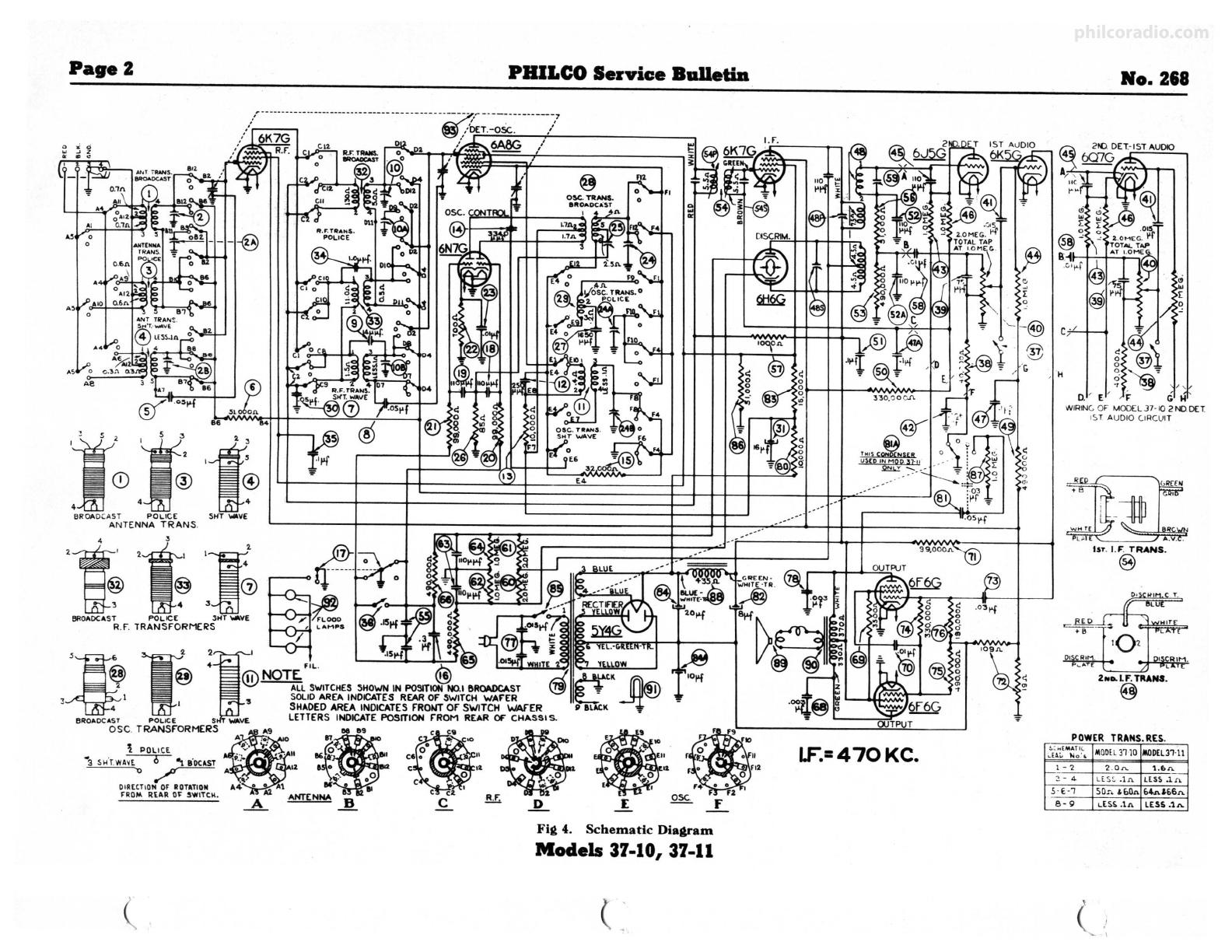
1.F.UNIT 3'7-10J 37-11
,..._ ,..._
Fig. 6. 37-10-11 R. F., I. F. Base View and 37-10 Power Unit Base View
Replacement Parts-Models 37-10-11
Schem.
No. Part List Schem . Part
D-iption No. Price No. D-iption No.
42
43
44
45
46
47
48
49
50
51
52
53
54
55
56
57
58
59
60
61
62
13
64
65
86
87
88
89
70
71
72
n
74
75
78
77
78
Condenser (.006mfd. tubular) ...... 30-4445 $0.20 Gower Transformer (115 V., 50
Resistor (l.O megohm, ½ watt) . 33-510339 .20 to 60 cycles) ...... . .. .. .. ... 32-7640
Resistor (l.O megohm, ½watt) . 33.,';10339 .20 79 3i-ll Power Transformer (115 V., 25
Condenaer (110 mmfd . mica) .. . . 30-1031 .20 to 40 cycles) . .. .. ... . . ... . .. 32-7641
Resistor (l.O megohm , ½ wat.t) 33.,';10339 .20 Power Tran ·,former (115-240 V.,
Condenser (.1 mfd. dual bakelite) .. . .. 4989-DG .40 50 to 60 cycles) ... .. . . . ..... 32-7642
2nd I. F. & Diacriminator Transformer 32-2362 3.30 80 37-10 istnr (10,000 ohms, 2 watt) . . 33-310639
Resistor (490,000 ohms,½ watt) . .. . . 33-449339 .20 81 Condenser (.05 mfd. bakelite) 37-10... 3615-SU
Resistor (330,000 ohms . ½ watt) . . 33-433339 .20 Condenser (.03, .05 mfd. bakelite) 37-11 3615-YU
Condenser (.l mfd. tubular) .. . ....... 3~455 .25 82 Electrolytic Condenser (8 mfd.) .. . .... 30-2024
Condenser (110 mmfd. dual bakelit e).. 8035-DG .25 83 Resistor (15,000 ohms, 3 watt).. . . . . 33-315639
Resistor (490,000 ohms, ½ watt) . . . . . 33-449339 .20 84 Electrolytic Condenser (10, 20 mfd.) . . 30-2183
1st I. F. Transformer ....... ..... . ... 32-2333 2.20 85 Bass Comp . Cont rol & A.C. owitch
Condenaer (.15 mfd. dual bakelite) .... 6287-DG .40 (37-10) ... . . . . ....... .... . ... . .. . 42-1267
Resistor (51,000 ohms, ½watt) .... . . 33-351339 .20 Bass Comp. Control & A.C. switch
Resist-Or(1000 ohms, ½watt) . . . .. . .. 33-210339 .20 (37-11) .. . .... . .. . . . . ... . .... . . . . 42-1268
Condenaer (.01 mfd. tubular) ......... ~479 86 Resistor (51,000 ohms, 1 watt) . .. . ... 33-351439
Compensator .. . . ... . .. . . . . . . . . . .... 31-6147 .40 117 Resistor (1 megohm, ½watt) ........ 33-510339
Resistor (2 megohm s, ½ wstt) . . . . . . . 33-,520339 .20 88 Speaker Field Aasembly (H30) .. . . . . . . 36-3687
Resistor (2 megohm ,. ½ wat.t) .. . . . .. 33-520339 .20 89 Cone Voice Coil (H30) . . ....... . . ... 36-3801
Resistor (l megohm, ½ watt) .. . . . . . . 33.,';10339 .20 90 Output Transformer (H30) . . . . . . . 32-7754
Condenser (110 mmfd. dual bakelite) .. 8035-DG .25 91 Pilot Lamp .... . . ... . . . .. . . . . 34-2039
Resistor (l megohm, ½watt) .. . . . . .. 33-510339 .20 92 Floodlight Asaembly ......... 38-8210
Resistor (490.000 ohms,½ watt) .. 33-449339 .20 93 Tuning Conden ser ... . . . ... 31-1948
Resistor (490,000 ohms, ½ watt) . 33-449339 .20 Antenns Terminal Panel.. .... . . . . 38-7714
Speaker Cord... . . .. .. . . . . . . 41-3258 Automatic Dial Aaaembly . .. ... 31-1949
Condenser (.003 mfd. tubular) . 3~469 .20 Brace (Drive Mtg.) .. . . . . . . . . . . 28-4119
Resistor (3500 ohms,½ watt) . 33-235339 .20 Bracket /Drive Mtg . Assembly). 31-1901
Condenser (.01 mfd. tubular) . 3~169 .20 Cable & Plug (Pilot lamps).. . . U-3253
Resistor (99,000 ohms, ½watt) .. 33-399339 .20 8:~l:t0~:rg ~Sp'."."'~~)·.:·. : :: : : : : .. . t!'ti2:a
8
Resistor (Bias)... . . .. . . . . . .. 33-3280 .30 Coupling Asaembly (Tuning Shaft) ... 31-1961
Condense r (.03 mfd. bakelite) . 8318-SU .35 Set Screws Assembly . . . . W-650
Resistor (330,000 ohms, ½ watt) . . . 33-433339 .20 Set Screws Assembly;. . . . . . . . . . .. .. . W-644
Resistor (490,000 ohms, ½watt) .. . . 33-449339 .20 C<_>ntrolScrews (Stst,on Index) ... .. .. 31-1898
Resistor (190,000 ohms , ½watt) .... . 33-419339 .20 Dial. ·· ·: ····· · · · · · · · · · · · · · · · · · 27.,';271
Condenser (.015 mfd . dual bakelite) ... 3793-DG .40 g:1t:~ii~id~;'......·· · ···· :I:=
Condenaer (.003 mfd. tubular) . . . . 30-4469 .20 Dial Escutcheon Assembly . .. .. .. . . .. 45-2324
[Power Transformer (115 V., 50 Gesr No. l Front (Dial Aasembly) .... 45-2347
to 60 cycles).. . . . . . . . . . 32-7606 6.25 Gesr No. 2 Rear (Dial Asaembly). . . . 45-2348
79 37 lOlPower Transformer (115 V., 25 Handle (Dial) . .... . ........ . ... . . . . 45-2329
· to 40 cycles) . . . . . . . . . . 32-7607 9.00 Handle (Hub Assembly) . .. . . . . 45-2344
Power Transformer (115-240 V., Housing (Control Screw) 28-7196
50 to 60 cycles) .. . . . . . . . 32-7608 8.00 Mask Guide . . . . . . . . . . . . . 28-4118
Prices Subject to Cha " ·) Without Notice
Lill
Price
S0.30
.35
1.10
.30
2.00
.20
.20
4.00
1.50
.07
2.40
3.75
.15
25.00
.05
1.80
.40
.40('
I.SOC
.15
1.00
.03
.40
.60
1.00
.25
Schorn. Part
No. DOK<iptlon No.
Mask . . . . . .. . . . . . . . . . . . . 27.,';272
Mask & Link Assemb ly . . 45-2367
Pilot Lamp Assembly . . . . . . . . . . . . . . 38-8407
Pilot Lamp Assembly (Auto Dial) . 38-8210
Ring (Retaining Handle Hub) . . . . . . 28-8630
Ring (Retaining Mask Assembly) . 28-7195
Reflector Ring . . . . . . 28-4099
Range Switch Ant . 42-1200
Range Switch R. F ..... 42-1245
Range Switch Osc... .. . . . . . . . . . . . . . 42-1274
Range Switch Index Plate & Shaft . 42-1265
RAllj!eSwitch Shaft Couplin g. 28-7198
Stst ,on Tab Kit .. . . . . . . . . . . 40-6056
Set Screw. . . . . . . . . W-481
Socket (7 Prong) . . 27-6057
Socket (8 Prong) . . 27-6058
Socket (Rectifier) .. .. . . . . . . .. .. . . 27-6052
Shield (Tube) (Squar e). 27-2726
Shield Base. .. . . .. . . . . .. 28-3898
Shield Tube (Round) ... , . . 8005
Shaft (Volume Cont rol) .. .. 38-8198
Paper Tube (Vol. Shaft) . . 27~0
Retaining Chp (Vol. Shaft) 28-4394
Spring (Vol. Shaft) . . . . . . . . . . 28-4117
Spring (Mask retainin g ring). 28-8629
Speaker (H-30) . 36-1295
Vernier Drive . . . . . . . . . . 45-2342
Washer (Dial ring contact) .. 27-8361
Washer (Dial scale) ... . 27-83~8
CABINET PARTS
37-10
Baffle (Wood) (Speaker) .
Baffle & Silk Assembly . 37-11
Baffle & Silk Assembly ..
Baffle (Wood) (Speaker) .
37-10-11
Bezel Asaembly .
Cover (Besel).
Gasket (Besel) .......... .
Knob (Range S..-itch) ..
Knob (Tunin g) . .... .... . .
Knob (Tuning Vernier) .
Knob (Tone & Volume).
23553
40.,';976
4~15
24231
40.,';980
28-4077
27-8517
27-4326
. .. .. 27-4330
. 27-4331
27-4332
)
LIii
Pric,
$0.60
2.40
.02
.20
.35
.50
.15
2.00 C
.JO
.03
.JO
.01
.01
.40 C
.04
2.40
.01
.60
1.00
.25
.05
.JO
.10
.10
.JO
philcoradio.com
Page4 PHILCO
Service Bulletin No. 268
Fig. 7
Alignment of Compensators
EQUIPMENT REQUIRED: (1) Signal Generator; Philco Model 088 (fun-
damental frequency 110 to 20.000 K. C.) is the correct instrument for this purp0se;
(2) Output meter; Philco Model 025 Circuit Tester incorporates a sensitive output
meter and is recqmmended; (3) Fibre handle screw-driver (Philco Part No. 27,7059);
(4) Special v.aria:ble condenser (Philco Part No. 45-2325 ).
OUTPUT METER: The 025 Output Meter is connected to the plate and cathode
terminals of one of the (6F6G) tubes . Adjust the meter to use the (0-30) volt scale.
INTERMEDIATE FREQUENCY CIRCUIT
1. Set controls as follows: a. Magnetic Tuning 00 off0 0
b. Bass compensation minimum
c. Volume control maximum
d. Receiver Dial 580 K. C.
e. Signal Generator 470 K . C.
2. Adjust the I. F. compensators for maximum with signal generator output lead
connected through a .I mfd. condenser to the grid of the tubes as follows:
Input Point· Compen81ltora In Order
6K7G-lst I. F. (59) (48P)
6A8G-lst Det. (54S) (54P)
RADIO FREQUENCY CIRCUIT
Tuning Ranae 7.35 to 22 M. C.
1. Connect the signal generator outp ut lead through a .I mfd. condenser to
terminal I and the generator ground to terminal 3 on aerial input panel. Terminals
2 and 3 must be connected with the shorting link provided on the aerial panel.
2. Other controls set as given under intermediate frequency circuit, with the
exception of those as follow:
Range St,nal
Switch Generator
3 18 M. C.
3 18 M . C.
3 18 M. C.
Recelv .er
Dial
18 M. C.
18M . C.
18M . C.
Compen81ltors
In Order
(24B) See Note A
(10B) (2B) Use shunt condenser
on (24B) (Note B)
(24B) (Note A)
18M.C.
18M.C. R.F.
18M.C.
Fig . 8. R. F. Compen81ltors, Underside of Chassis
Tuning Range 2.3 to 7.4 M. C.
Adjust compensa tors for maximum as follow s:
Range Signal Receiver
Switch Generator Dial
2 7 M. C. 7 M. C.
1 6 M . C. 6 M. C.
Tuning Range 530 to 1720 K. C.
Adjust compensators for maximum as follows :
Compensator•
In Order
(24A)
(IOA) (2A)
Range Signal Receiver Compensators
Switch Generator Dial In Order
1 1600 K. C. 1600 K. C. (24) (10) (2)
I 580 K. C. .580 K. C. (2Sl Roll gani:
t 1600 K. C. 1600 K. C. (14)
t 1500 K. C. 1500 K. C. (10) (lJ
MAGNETIC TUNING ADJUSTMENT
Set the range switch in position one (530 to 1720 K. C.) and the magneti c
tuning switch in the "out., position. Now turn the signa l generator and receiver
dial to any frequency in the Broadcast band. The receiver dial must be adjusted
very accurately for maximum output.
Set the mag netic tuning control in the "'on" position (clockwise) . Compensator
(48S) of the magnetic tuning transformer is now adjusted for maximum output.
The above adjustment is now checked for accuracy, by turning the magnetic
tuning control "off" and "on" . When this is done, there should be no change In
the tone of the received signal. If a change of tone or hiss develops, it indicates a
shift in frequency and the adjustment must be made again.
NOTE "A"-To accurately adjust th e compensator to the fundamenta l and
not the image signal, turn the oscillator compensator to the maximum capacity
position clockwise . Then slowly turn the compensators counter-clockwise until a
second maximum peak is obtained on the output meter. The first peak is the
image signal and the receiver must not be adjusted to it. If the above procedur e
is correctly performed, the image signal will be found 940 K. C. below the frequen cy
being used.
NOTE "B"-To eliminate the effect of the R. F. compensat or detuning the
Osc. circuit, a variab le tuning condenser, Philco Part No. 45-2325 is connected
from the oscillator compensator to ground when designated in the padding instruc-
tion above . Tune the added condenser until the second harmonic of the receiver
oscillator beats against the signal from the generator . resulting in a maximum
.indication on the output meter . Then adjust cortlpensators as noted for maximum
output.
A Necessity FOR EFFICIENT SERVICING
Here is a piece of equipment that any dealer or
service station owner can use in many ways both
for service and profit. Ruggedly and attractively
constructed of heavy steel, cadmium plated, this
rack is ideal for speedy testing _and working on
all standard sized radio chasses.
It is also especially suitable for arranging special
window displays of chassis. Four adjustable
support arms with wing nuts permit use of any
size or shape chassi.s with equal ease .
Order one from your Philco distributor today.
New
PHILCO CHASSIS-RACK
for
SHOP WORK
or DISPLAY USE
Dimensions overall:
Height 11¾" Depth 14" Length 17 "
LIST S6
PART No. 45-2310 PRICE 00
PHILCO RADIO AND TELEVISION CORPORATION
Philadelphia, Pa~
Novcml,cr I9J6 Print ed in U.S. A
philcoradio.com

Other manuals for 121

8

This manual suits for next models

2

Other Philco Radio manuals

Philco 116 User manual

Philco

Philco 116 User manual

Philco 121 User manual

Philco

Philco 121 User manual

Philco 37-675 User manual

Philco

Philco 37-675 User manual

Philco 96 User manual

Philco

Philco 96 User manual

Philco 121 User manual

Philco

Philco 121 User manual

Philco 200 User manual

Philco

Philco 200 User manual

Philco PHOTOFACT 49-1150 User manual

Philco

Philco PHOTOFACT 49-1150 User manual

Philco D-592 User manual

Philco

Philco D-592 User manual

Philco 37-660 User manual

Philco

Philco 37-660 User manual

Philco 121 User manual

Philco

Philco 121 User manual

Philco 80 User manual

Philco

Philco 80 User manual

Philco 144 User manual

Philco

Philco 144 User manual

Philco 37-630 User manual

Philco

Philco 37-630 User manual

Philco 37-670 User manual

Philco

Philco 37-670 User manual

Philco 643 User manual

Philco

Philco 643 User manual

Philco 39-55 User manual

Philco

Philco 39-55 User manual

Philco 77 User manual

Philco

Philco 77 User manual

Philco 37-60 User manual

Philco

Philco 37-60 User manual

Philco 15 Series Reference manual

Philco

Philco 15 Series Reference manual

Philco 16 Reference manual

Philco

Philco 16 Reference manual

Philco 650 User manual

Philco

Philco 650 User manual

Philco 66 User manual

Philco

Philco 66 User manual

Philco PRR1005BT User manual

Philco

Philco PRR1005BT User manual

Philco 37-620 User manual

Philco

Philco 37-620 User manual

Popular Radio manuals by other brands

Hama Badradio SR-300 Operating	 instruction

Hama

Hama Badradio SR-300 Operating instruction

GME TX3100VP instruction manual

GME

GME TX3100VP instruction manual

HPSDR Excalibur Assembly and operation instructions

HPSDR

HPSDR Excalibur Assembly and operation instructions

PRESIDENT JOHNSON II owner's manual

PRESIDENT

PRESIDENT JOHNSON II owner's manual

Sangean WR-15WL manual

Sangean

Sangean WR-15WL manual

Sony ICF-M770L Service manual

Sony

Sony ICF-M770L Service manual

Motorola CLP series Quick reference guide

Motorola

Motorola CLP series Quick reference guide

TechniSat DIGITRADIO 231 OD manual

TechniSat

TechniSat DIGITRADIO 231 OD manual

Trevi MRA 784USB user guide

Trevi

Trevi MRA 784USB user guide

Mx Onda MX-RDM5240 instruction manual

Mx Onda

Mx Onda MX-RDM5240 instruction manual

Grace Digital GDI-IR2600 user guide

Grace Digital

Grace Digital GDI-IR2600 user guide

Motorola PM1500 user guide

Motorola

Motorola PM1500 user guide

Alcatel-Lucent 9500 brochure

Alcatel-Lucent

Alcatel-Lucent 9500 brochure

Motorola Commercial Series Selling guide

Motorola

Motorola Commercial Series Selling guide

Team Electronic PT-3508 (3) manual

Team Electronic

Team Electronic PT-3508 (3) manual

Radio Shack 22CH GMRS/FRS owner's manual

Radio Shack

Radio Shack 22CH GMRS/FRS owner's manual

GE 7-2946 Specifications

GE

GE 7-2946 Specifications

Medion LIFE S66004 instruction manual

Medion

Medion LIFE S66004 instruction manual

manuals.online logo
manuals.online logoBrands
  • About & Mission
  • Contact us
  • Privacy Policy
  • Terms and Conditions

Copyright 2025 Manuals.Online. All Rights Reserved.