manuals.online logo
Brands
  1. Home
  2. •
  3. Brands
  4. •
  5. Philco
  6. •
  7. Radio
  8. •
  9. Philco 121 User manual

Philco 121 User manual

• •?rli,dRIA39-30mul 39-35,CJJ.dJt.121
SERVICEBULLETINNo. 304 lo, members ol
RADIO MANUFACTURERS SERVICE
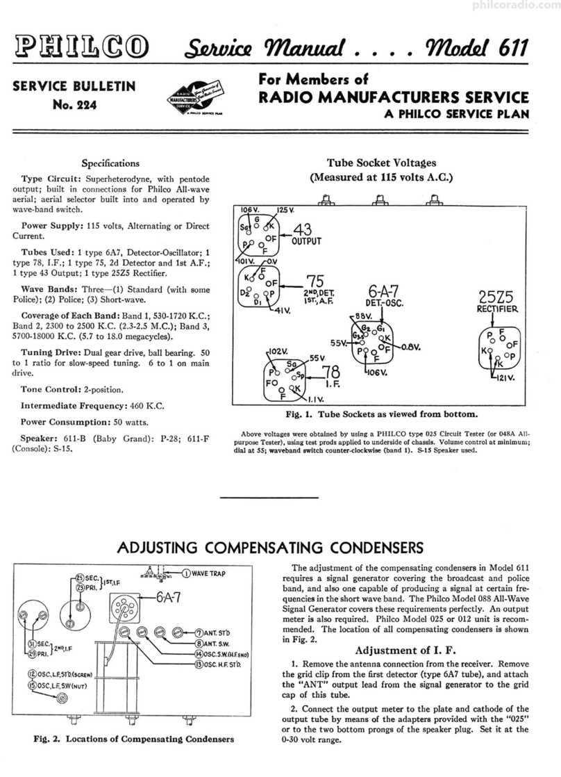
Specifications
TYPE OF .CIRCUIT: A. C. operated; superheterodyne circuit
with two tuning ranges, covering standard broadcast (540 K. C.
to 1720 K. C.) and short-wave (4.9 M. C. to 18.0 M. C.) fre-
quencies; Automatic Volume Control; and pentode output.
The receiver is designed to operate from a "Philco Safety
Aerial," Part No . 40-6371. This aerial system should be used
to obtain maximum performance fr6m the receiver.
POWER SUPPLY: Voltage, 115 volts . Frequency , 50-60 cycles.
Power consumption 45 watts.
INTERMEDIATE FREQUENCY: 470 K. C.
TUNING RANGES: 540 K. C. to 1720 K. C.; 4.9 M. C. to 18.0
M.C.
PHILCO TUBES USED: 1-6A8G, 1st detector and oscillator;
1-78, I. F . ; 1-37, 2nd detector , Automatic Volume Control; 1-75,
first audio; 1-41, output; and 1-84, Rectifier .
TUNING MECHANISM: Pulley and cable drive for Manual
tuning. Electric Push-Button for Automatic tuning.
CABINETS: Types: "T" for 39-30 and "XX" for 39-35.
A PHILCO Ser.Yice Plan
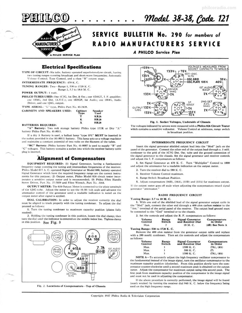
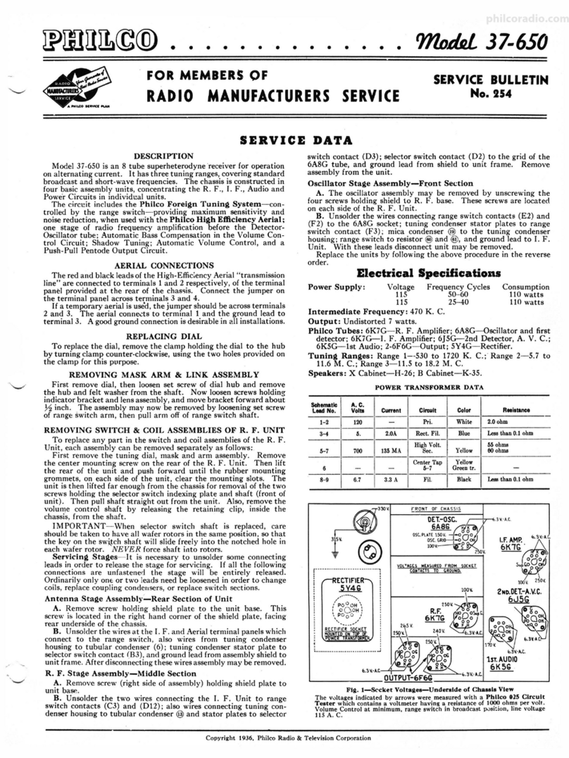
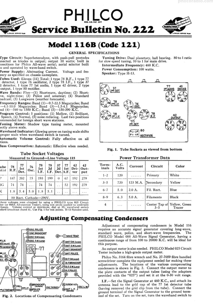
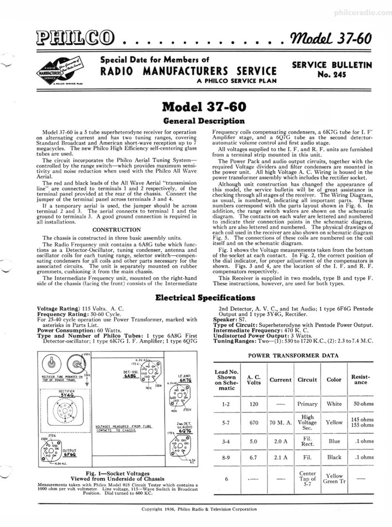
VOLTAGES MEASURED FROM SOCKET
CONTACTS TO CHASSIS.
DETO$C..
6MIC.
Iii~~
11urnv...
0•
1su•
2NO DET AVC.
37
~42
UV.
Fig. 1. Socket Voltages-Underside of Ch!ls•i•
\..!Jt•
an mv
I.F 711
The voltages indicated hy arrows were measured with a Philco 027 Circuit
Tester which contains an accurate voltmeter. Volume control at minimum,
range switch in broadcast position, line voltage 115 A. C.
Adjusting Push-Button Tuning to Stations
These detailed instructions have been prepared to make sure the
correct procedure is followed in setting the stations on the Philco
Electric Push-Butt01i Tuning models. The work requires the use
of a Philco Model 077 Station Setter and a Part No. 27-7059 Insu-
lated Screw Driver.
(A) Select eight of the most popular stations rEceived in the
locality and remove their call letters from the call letter sheets sup-
plied. Place the call letters in the windows above the buttons, making
such that each respective button covers the frequency of the station
for which it is to be used. The frequency range of the circuits are
as follows: Circuits
I and 2
3 and 4
5 and 6
7 and 8
Frequency Range
540 to 1030 kilocycles
670 to 1160 kilocycle6
900 to 1470 kilocycles
1170 to 1600 kilocycles
These numbers are stamped on the unit as seen from the rear.
Looking at the front of the cabinet the numbers read from left to
right.
(B) Connect the aerial and ground to the "ANT" and "GND"
terminals of the receiver .
(C) Turn the receiver Tuning Range Selector to position two
(Manual Tuning) and tune the receiver to the station to be set on
the first button.
(D) Plug the output leads of the Station Setter into the "High"
and "Gnd" jacks, and turn the output controls to maximum. Turn
the modulation control to "Modulation Off." Connect the output lead
of the Station Setter to the "ANT" and "GND" terminals of the
receiver and tune to the frequency of the station being received. As
the indicator is slowly tuned through the frequency of the station
there will be two points at which a high pitched swish will he heard,
one above and one below the frequency of the station. \Vhen the
indicator is on the frequency of the station , minimum high pitched
swish will be heard.
(E) Set the modulation control of the Station Setter for "1fodu-
lation On.' ' The modulated signal of the Station Setter will then be
heard through the receiver.
(F) Turn the receiver Tuning Range Selector to position one
(Automatic Tuning) and push in the first button . Using the Part
Ko. 27-7059 Insulated Screw Driver , turn the number 1 "OSC"
screw until the modulated signal of the Station Setter is tuned in
to maximum volume. Then adjust the number 1 "ANT'' screw for
maximum signal.
(G) Remove the output lead of the Philco Station Setter from
the •·A\" T" terminal of the receiver and turn its indicator off the
frequency of the station. The program of the desired station will
then be heard on the receiver.
( H) With the volume of the receiver low, slowly turn the num-
ber I "OSC'" screw back and forth until maximum output is received.
Repeat the same proceduN! for the number l "A\"T" screw.
After setting up the first station, the same procedure given under
(C) to (H) is used for the other stations.
Copyright I938, Philco Radio and Television Corp.
philcoradio.com
Page 2
4
)
NOTE
L[TTCIIS INDICATE ~OSITION or SWITCH
WAr[RS rllOM ll[AII or CHASSIS IOTTOM VICW.
ALL WIN[ SWITCHU SHOWN IN POSITION .... .1
~USH IIUTTON
SOLID AREA INDICATES RING AT R[AII OF
SWITCH WAFEII
SHA0£D AIICA INDICATU RING AT rRONT OF
IWITCH WAr~A
PHILCO Service Bulletin No. 304
•t)r ···7
, TUNING /
DET.-os<;: 4 coNocNsER :
6A8G: . / 2ND.DET.
AV.C. fJ ®
G~
~
·
~
__.:•(1
..
I I t t
~-
-:k~
I ·• f
I _......--
1 I ., ••
_... -11,,t
,,..
~
2
3o°/I
DIRECTION or IIOTATION
fROM IIEAR OF SWITCH .
"?
®Q
....--
,...............
........ FllAfl'l[NTS-
Fis. 2. Schematic Diacram-Moclela 19-S0; 39-35, Code 1%1
~-----
__.._........-....--
,,...-"".....
"i'
I.r.=470 KC.
MOO.st-JO
M00 .39-35
philcoradio.com
No. 304 PHILCO Service Bulletin Page 3
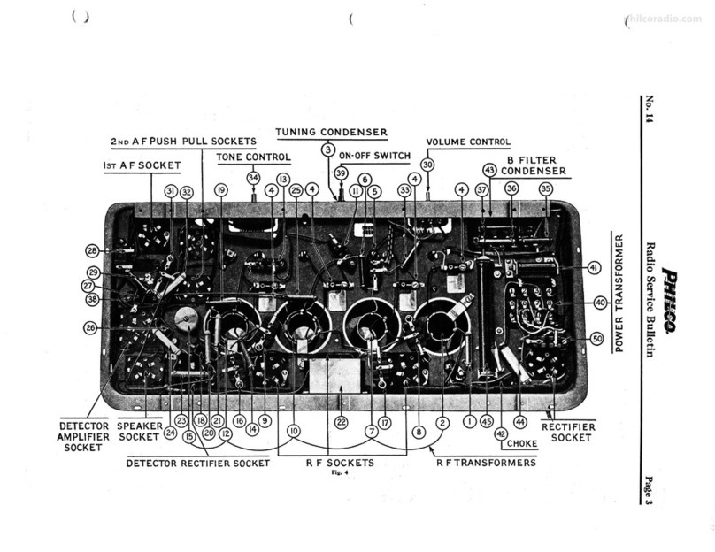
Fl•·a.Part• Locatlon9-Under•lde of Chaule
Replacement Parts
Schent. Schent.
No.
1
2
3
4
!S
6
7
8
9
10
11
12
13
14
15
16
17
18
19
20
21
22
23
24
25
26
27
28
29
30
31
32
33
34
35
36
37
38
39
40
41
42
43
44
45
46
Description
Antenna Transformer (short wave) ..........•.... .. . .. .
Antenna Transformer (broadcast) .. . ... . . .. .. •. . . . .. , .. .
Condenser (.05 mf., tubu lar) .... ....... ... . .. , .. , . ..... .
Ii:~\nia~d~~•uift -~~~e-~~~~ :::::::: ::: : : : : : : : : : : : : : : : : : :
Oscillator Transformer ..... .. . ......... . . .. . . ... ... . . . .
Condenser (250 mm!., mica) ....... .. .....•.............
Condenser (4500 mm!., mica) . .... ... . .. . .. . .•. . . , ..... .
Resistor (51,000 ohms, ½ watt) . . .. ..... .... ..... . .. .... .
Condenser (370 mm!., silver plated mica) .. ..•.... .. .....
Condenser (370 mm!., silver plated mica) . ....... , . ..... .
1st I. F. Transformer Assembly ....... .. ... •..... . .• . .•.
Condenser (.1 mf., tubular) ....... .... ......• . ... . ......
Resistor (32,000 ohms, ½ watt) . .... . .....• . .. .... . ... .
Resistor (3000 ohms, ½ watt) ....... . ...... ... ..... ... .
Resistor ( 5000 ohms, ½ watt) . . .. ..... ... .. . . ......... .
Electrolytic Condenser (16 mf., 250 V.) ..........•.......
Electrolytic Condenser (16 mf., 250 V.) .. . . . .....•.......
Condenser (110 mmf., mica) ........ .... •.. . ... . ...... . .
2nd I. F. Transformer Assembly .. ...... .. ..... ........ .
Resistor (51,000 ohms, ½ watt) ........................ .
Condenser (.003 mf., tubular) ...... . ... ... ... .. ... ..... .
Resistor (490,000 ohms, ½ watt) .. ........•... .. ........ .
Volume Control (2.0 megs) .... .. .. . ..... •. ... .•... .. .. .
Resistor (32,000 ohms, ½ watt) . .. ..•. .. ,, • ...... . .. • . . .
Condenser (.006 mf., tubular ) . ... . , . ..... ....•. .... .....
Condenser ( .05 mf., tubular) ... ......... .•. , ...... . • ...
Resistor (2.0 meg., ½ watt) .. ... . .•...... .... . ........
Resistor (1.0 meg., ½ watt) ... ......... .. ........... ..
Condenser (.015 m'f., tubular) . .. ... , ....... •.... . , ... . . .
Resistor (4.0 megs., ½ watt) ......... .. .............. ..
Resistor (70,000 ohms , ½ watt) ... . . .. , ..... . ... ... , .. .
Resist or (750 ,000 ohms, ½ watt) ... ...... . , . ..... , . . , .. .
Condenser (250 mf., mica) .. ..... , .. • ...... .. , ... , . . ... .
Condenser (.01 mf., tubular ) ...... .. .... . ..•... .... .....
Output Transformer ............................. . .... .
tConc and Voice Coil Assembly
Part No.
32-3027
32-3026
30-4519
31-2267
31-6255
32-3028
30-1032
30-1109
33-351339
30-1110
30-1110
32-3018
30-4455
33-332339
33-230339
33-250339
30-2331
30-2331
30-1031
32-3030
33-351339
30-4469
33-449339
33-5275
33-332339
30-4467
30-4518
33-520339
33-510339
30-4515
33-540339
33-370339
33-475339
30-1032
30-4572
32-7978
for 39-30 T, speaker pt. No. 36-1439-3 ... .. .. .. ....... . 36-4091
for 39-30 T, speaker pt . No. 36-1439-2 . .. ... . ... . ...... 36-4087
for 39-35 XX, speaker pt. No. 36-1438-2 ......... ... .... 36-4089
Condenser (.03 mf., tubular) ...• . ... ... •............... 30-4449
Condenser (.006 mf., tubular) . . ... . ....... , .... .. ... . .. . 30-4445
Tone Control and On-Off Switch ...... .. ... , ... . .. , . .... 42-1444
Condenser (.01 mf. - .01 mf., bakclite) .... . . , ......•. .... 3903 DG
Power Transformer : 115 V., 60 cycle:
for 39-30 ............. .. . .. ... .. .. . ... . .•...... .. ...
for 39-35 .. ..... . . .. . .... . ... ......... , .. , . .•..... ..
Electrolytic Condenser (8 mf., 400 V.) . . ... . .. ...... . . . ,
32-7976
32-7977
30-2330
*Field Coil for Speaker, part No. 36-1439 ..... •. .... . .. ...
*Field Coil for Speaker, part No. 36-1438 ... . .•..... ... . . .
Resistor (280 ohms, wire wound) ... . ...... .. , • , . .... , . . . 33-128431
Resistor (70 ohms, ½ watt) ............. . .. ... ......... 33-070339
No. Description Part No.
47 Push-Button Switch ... . .. ... .... ....... . .......... , .. .. 42-1446
48 Padder Strip Assembly.. .. .. .. .. .. .. . . .. .. .. . .. .. .. .. .. 31-6256
48A Compensator, No. 1, 540-1030 KC .. . .. , .. .... .. .... . . 31-6274
481 Compensator, No. 2, 540 - 1030 KC .... . • .. , . .. . ..•.... 31-6274
48C Compensator, No. 3, 670 - 1160 KC .............. ...... 31-6276
48D Compensator, No. 4, 670 - 1160 KC ........ . .. .. ....... 31-6276
48E Compensator, No. 5, 900 - 1470 KC .... , . .. . .. ......... 31-6278
48F Compensator, No . 6, 900 - 1470 KC .... • ..... .•...... .. 31-627 8
48G Compensator, No. 7, 1170 - 1600 KC .. ... . .... .. .. . ..... 31-6280
48H Compensator, No. 8, 1170 - 1600 KC ..... , .. , . •. . .. . .... 31-6280
49 Electric Push-Button Coil Assembly .. . ...... .. . . ... .. . . . 32-·3031
49A Osc . Coil, No. 1, 540 - 1030 KC ........... . . .. • ..•.... 32-3042
491 Osc. Coil, No. 2, 540 - 1.030 KC .... . .. ...... ........ .. 32-3042
49C Osc. Coil; No. 3, 670 - 1160 KC. .............. . . .. .... 32-3042
49D Osc . Coil, No. 4, 670 - 1160 KC . . . .....•.. • ... .. ..... . 32-3042
491 Osc . Coil, No. 5, 900 - 1470 KC ....... . ...•... . ....... 32-3041
49F Osc. Coil, No. 6, 900 - 1470 KC .....•..... ... ......... 32-3041
49G Osc. Coil, No. 7, ·1170 - 1600 KC .... .. . .. .. .... . .. .... . 32-3041
49H Osc . Coil, No. 8, 1170-1600 KC .......... ... .. .. .... .. 32-3041
50 Wave Switc h . . . .... ... . ...... .. ...... . . .. .. . .... . .. . . . 42-1445
51 Pilot Lamp ..... .. . . ............... , .... ..... . .. . ..... 34-22 10
Bezel Assembly ....... . .. . .. . ... ... ........ • .. . , . . . . . . . . . . . . 40-6365
Bezel Gasket . ..........•..• , . . .....•..... , .. , ... . ... .. , ... . . 27-9175
Bezel Screw ... . .......... . ......... . ....................... W-1834 ·
Cable (Speaker) . ....... . ........ .. .. . , . .. ...... . ............ 41-3443
Cable (Power) ... .... . . ... .. . . .....•..... , .. , . . . . . . . . . • . . . . . L-2778
Dial Scale . .. .. .. ............ . .... ... ... . .......•...... . . ... 27-5403
Dial Spring ....... .. ... . ............. . .•.. .. . . .. ...... , . . . . . 28-8908
Dial Pointer ....... ·• ........ . ......................... . ... . 28-5941
Dial Drive Cord Assembly. . . . . . . . . . . . . . . • . . . . . . . . . . . . . . . . . . . . 31-2269
Dial Drive Cord Spring .... ..... ... . ..... ........ . . .. .. ..... . . 28-8913
Dial Drive Drum .... ....... . .... . , .. •.. . • .... . • . . , ..•... • .. .. 31-2281
Dial Tuning Shaft Assembly . ..... ..... ........... .......... . . . 31-2260
Kn ob ........... . ... ... . .. .. . .... ..... ... ........ . .. ........ 27-4332
Mounting Rubber (Chassis).• , ...... . .....• . . , .. • . .....•... ... . 27-457'1
Mounting Rubber (Chassis Cornerj ...... . ...... • ..... . ...•.... 27-4564
Mounting Screw (Chassis) .... ....... .......... .. ........ .. .. . W-1345
Pilot Lamp Socket Assembly. . . . . . . . . . . . . • . . . . . • . . . . . . . . . . . . . . 38-9607
Push-Button . ... .. . . .... ......... .... ..... . .. •..... ..... .. . . 27-4759
Speaker (T Cabinet 39-30) optional. ..... . . , · ·, • •, · · · · · · · · ••• · } ltmt~
Speaker (XX Cabinet 39-35) ... ... .. . .... , . .... , .............. 36-1438
Socket (5 Pr ong) ... , ..................... . ...... , . . . . . . . . . . . 27-6035
Socket (6 Pr ong) . .... ............. ..... . . .... ... . .. .. . .. . .... 27-6036
Socket (7 Prong) ........ . ..•..... • .. , ............•...... . .... 27-6099
Tab Kit . . . . . . . . . . . . . •. . . . . •. . . . . . . . . . . . . . . . . . . . . . . . . . . . . . . . . 40-6392
* Replace Speaker
t Model T Cabinet uses two optional speakers . The part numbers of the
speakers arc the same with the exception of a dash number (-2 or -3) fo.llow•
ing the part number. When ordering a Cone and Voice Coil Assembly, the
part number as indicated must be specified.
philcoradio.com
Page 4 PHILCO Service Bulletin No. 304
Alignment of Compensators
EQUIPMENT REQUIRED:
(1) Signal Generator ; Philco Model 077 Signal Generator
which has a fundamental frequency range from 115 to 36,000
K. C. is the correct instrument for this purpose.
(2) Output meter , Philco Model 027 Circuit Tester, incor-
porates a sensitive output meter and is recommended.
(3) Philco Fiber Handle Screw Driver, Part No. 27-7059,
and Fiber Wrench, Part No. 3164.
OUTPUT METER: The Philco 027 Output Meter is connected
to the plate and cathode terminals of the type 41 tube. After
connecting the Output Meter, adjust compensators in the order
as given below.
Signal Generator
OutputOperations Dummy Dial
Connections Anterina Setting
To Receiver (Note A)
1 6A8G Grid .1 mf. 470 K. C.
2 Ant. Ter . 100mmf. 18.0 M.c.
3 Ant. Ter. 100mmf. 1550 K. C.
4 Ant. Ter . 100mmf. 580 K. C.
5 Ant. Ter . 100mmf. 1550 K. C.
NOTE A-The "Dummy Antenna" consists of a condenser con-
nected in series with the signal generator output lead (high
side) . Use the capacity as specified in each step of the above
procedure
□
~o
~Ym
g~
0
Fie. ,. Location• of Compenaaton--Top of ChU1i1
Receiver
Special
Control Adjust Instructions
Dial Settings Compensators
Setting In Order
580 K. C. Vol. Cont. (20A) (12B)
Max. (12A)
18.0 M. C. Vol. Cont. (4B) See Note B
Max .
1550 K. C. Vol. Cont. (5) (4A)
Max.
580 K. C. Vol. Cont. (SA)
Max .
1550 K. C. Vol. Cont. (5)
Max.
NOTE B-DIAL CALIBRATION: In order to adjust the re-
ceiver correctly the dial pointer must be aligned to track prop-
erly with the tuning condenser . To adjust the dial proceed as
follows: \Vith the tuning condenser closed. set the dial pointer
on the extreme left index line at the low frequency end of the
scale.
PHILCO RADIOS will give original Quality Performance only when
Genuine Philco Replacement Parts are used
June 1938
PHILCO RADIO AND TELEVISION CORPORATION
Parts aad Service DiYisio11
Plailadelpbia, Pa.
Printed in U. S. A.
philcoradio.com

Other manuals for 121

8

This manual suits for next models

2

Other Philco Radio manuals

Philco 16 Reference manual

Philco

Philco 16 Reference manual

Philco 116 User manual

Philco

Philco 116 User manual

Philco 80 User manual

Philco

Philco 80 User manual

Philco 650 User manual

Philco

Philco 650 User manual

Philco 121 User manual

Philco

Philco 121 User manual

Philco 121 User manual

Philco

Philco 121 User manual

Philco 118 User manual

Philco

Philco 118 User manual

Philco 37-116 User manual

Philco

Philco 37-116 User manual

Philco 37-660 User manual

Philco

Philco 37-660 User manual

Philco 37-630 User manual

Philco

Philco 37-630 User manual

Philco 66 User manual

Philco

Philco 66 User manual

Philco 29 User manual

Philco

Philco 29 User manual

Philco 28 User manual

Philco

Philco 28 User manual

Philco CSP790BC User manual

Philco

Philco CSP790BC User manual

Philco 37-675 User manual

Philco

Philco 37-675 User manual

Philco 144 User manual

Philco

Philco 144 User manual

Philco 37-620 User manual

Philco

Philco 37-620 User manual

Philco 623 User manual

Philco

Philco 623 User manual

Philco PHOTOFACT 49-1150 User manual

Philco

Philco PHOTOFACT 49-1150 User manual

Philco 121 User manual

Philco

Philco 121 User manual

Philco 121 User manual

Philco

Philco 121 User manual

Philco 96 User manual

Philco

Philco 96 User manual

Philco 121 User manual

Philco

Philco 121 User manual

Philco 37-60 User manual

Philco

Philco 37-60 User manual

Popular Radio manuals by other brands

Block AURORA manual

Block

Block AURORA manual

Nabishi PR302 quick start guide

Nabishi

Nabishi PR302 quick start guide

Sony ICF-506 operating instructions

Sony

Sony ICF-506 operating instructions

Weather X FR6817DT instruction manual

Weather X

Weather X FR6817DT instruction manual

MAJORITY EDDINGTON EDD-DAB-BLK Instruction guide

MAJORITY

MAJORITY EDDINGTON EDD-DAB-BLK Instruction guide

Sangean DDR-60BT manual

Sangean

Sangean DDR-60BT manual

Lanpro LP-1520ai manual

Lanpro

Lanpro LP-1520ai manual

jotron Tron TR20 PLUS user manual

jotron

jotron Tron TR20 PLUS user manual

Albrecht DR 52 BC manual

Albrecht

Albrecht DR 52 BC manual

EINHELL TC-RA 18 Li BT Original operating instructions

EINHELL

EINHELL TC-RA 18 Li BT Original operating instructions

Sony SRF 59 - Sports Radio Walkman Personal operating instructions

Sony

Sony SRF 59 - Sports Radio Walkman Personal operating instructions

Panasonic RF-2400 Service manual

Panasonic

Panasonic RF-2400 Service manual

Antique Automobile Radio 052314B operating instructions

Antique Automobile Radio

Antique Automobile Radio 052314B operating instructions

Curtis RCD302 Specification sheet

Curtis

Curtis RCD302 Specification sheet

Bosch GML SoundBoxx Professional 14,4 V Original instructions

Bosch

Bosch GML SoundBoxx Professional 14,4 V Original instructions

Uniden GRANT owner's manual

Uniden

Uniden GRANT owner's manual

Midland ALAN 48 EXCEL D80 user manual

Midland

Midland ALAN 48 EXCEL D80 user manual

SKYTERRA Msat G2 user guide

SKYTERRA

SKYTERRA Msat G2 user guide

manuals.online logo
manuals.online logoBrands
  • About & Mission
  • Contact us
  • Privacy Policy
  • Terms and Conditions

Copyright 2025 Manuals.Online. All Rights Reserved.