Page4 PHILCO Parts and Service Division No. ZSO
PHILCO
MODEL 025
CIRCUITTESTER
•
The Most Compact
Self-Contained Complete
Radio Circuit end Value
Testing Instrument
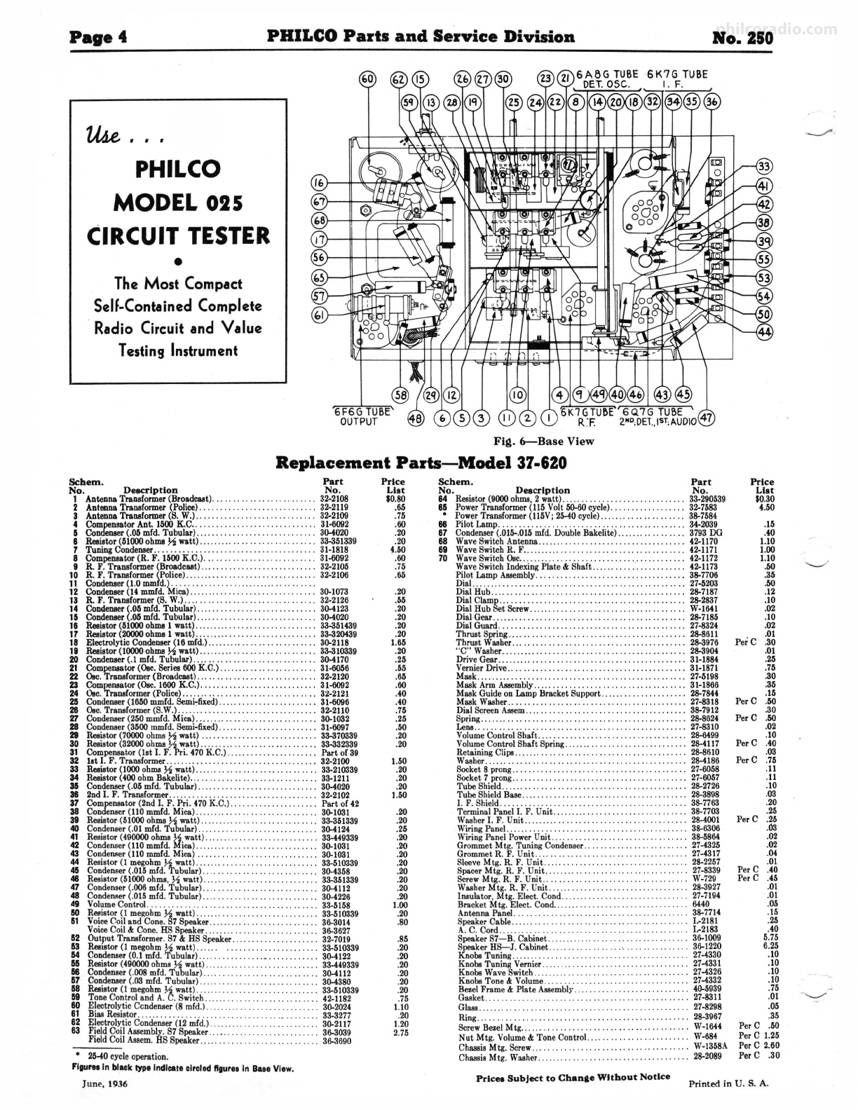
Fig. 6-Base View
Replacement Parts-Model 37-620
Schem . Part
No. Deecrlptlon No.
1 Antenna Transformer (Broadcut) .....•. ... ... •.. •.. ...... 32-2108
2 Antenna Transformer (Police).. . .... . ................ 32-2119
3 Antenna Transformer (S. W.).. ......... . ...... . .......... 32-2109
4 Compensal<,rAnt. 1600K.C....... .. ....... ....... ....... 31-6092
5 Condenser(.05mfd. Tubular).. .. .. .. .. .. .•.. .. .. .. .. .. .. . 30-4020
8 Reaiator(51000ohma½ watt).... ..... •• .. .. .. •. .•.. .. .. .. 33-351339
7 Tuning Condenser.................... .. ................. 31-1818
8 Compensator(R. F. 1500K.C.)........... ... ... .......... 31-6092
9 R. F. Transformer (Broadcaal)... .. .. .. .. .. . . .. .•. . .. .. .. . 32-210.S
10 R. F. Transformer (Police)........... ,....... ............. 3:i:,2100
11 Condenser (1.0 mmfd.)................. ... ............... .
12 Condenser(14mmfd. Mica)........ ...... ...... ... ........ 30-1073
13 R. F. Tranaformer (S. W.)............ ...... .............. 32-2126
14 Condenser(.05 mfd. Tubular) ........ .. ................... 30-4123
15 Condenser(.O.Smfd. Tubular) ............ .. ............... 30-4020
18 Reaiator(61000ohma I watt) ........ .. . ................... 33-351439
17 Reaiator(20000ohma I watt) ........... .. .... . ....... .. ... 33-320439
18 Electrolytic Condenser(16 mfd.).. ........... .. .. .. . . .... . . 30-2118
19 Reaiator(10000ohma½wall) .. ............... .. .... .... .. 33-310339
20 Condenser(.1mfd. Tubular)... . .. ........................ 30-4170
21 Compensator(O.C.Seriea600K.C.) ........ ................ 31-6056
22 O.C.Tranaformer(Broadcast).. .............. ... .. .. ...... 32-2120
23 Compell8&tor(O.C. 1600K.C.)........... ... . ........ , .... 31-6092
24 O.c. Transformer(Police)....... .. .. .. .. ..•. .. .. .. .. .. .. .. 32-2121
25 Condenser(1660mmfd. Semi,fixed). .... ... .• . .. .. ..• . ,.... 31-6096
28 O.C. Transformer (S.W.)......... .... ...... .... ........... 32-2110
27 Condenser(250mmfd. Mica)........ ........ .. ............ 30-1032
28 Condenser(3500mmfd. Semi-fixed)........ . .•.... ,....... . 31-6097
29 Reaistor(70000ohms ½ watt) .. . .. .. .. .. •.. . .. .. .. .. .. .. . 33-370339
30 Reaistor(32000ohms ½ watt). ... . ... . .. .. .. .. .. .. .•.. .. . . 33-332339
31 Compell8&tor(1st I. F.Pri.470K.C.)..... ...... ........... Part of 39
32 lat I. F. Transformer........ .... .................... .. .. . 32-2100
33 Reaiator(1000ohms½ watt) ................ .. ........ .. .. 33-210339
34 Reaistor(400ohm Bakelite)................. .. ............ 33-1211
35 Condenser(.05 mfd. Tubular) .......... . .. , .• .. ..• , .•..... 30-4020
38 2nd I. F. Transformer............... ..... . ........ .... ... 32-2102
37 Compell8&tor(2nd I. F. Pri. 470K.C.)..................... Part of 42
38 Condenser(110mmfd. Mica).. .... ........ ........ ........ 30-1031
39 Reaistor(51000ohms½ watt) ...... ... .... .... .. .......... 33-351339
40 Condenser(.01 mfd. Tubular) ..................... ........ 30-4124
41 Resistor (490000ohms ½ watt) .... .. .. . .. .. •. .• .. .. .. .. .. . 33-449339
42 Condenser(110 mmfd. Mica).............. .... ............ 30-1031
43 Conderu.er (110mmfd. Mica) ... . .. ... ... .... .. ..... . , .... 30-1031
44 Resistor (I megohm½watt) .. ............. .... ...... , . ... 33-510339
45 CondeDBer(.015mfd. Tubular) .... .. .. •• .• ... . .. 30-4358
48 Resistor (51000ohms, ½watt) ...... ... .... .... .. ......... 33-351339
47 Condenser (.006 mfd. Tubular) ................. .... ....... 30-4112
48 Conden•er(.015mfd. Tubulor)......... , .... ... , .. ........ 30-4226
49 VolumeControl. .. ............ .... ........ .............. 33-5158
80 Reaistor(I megohm½ watt) ................. .. ........... 33-510339
51 VoiceCoiland Cone:S7Speaker............. ...... .. .. .... 3f>-3014
VoiceCoil & Cone. HS Speaker.. .. .. .. .. .. .. .. .. .. .. .. .. .. 3f>-3627
52 Output Transformer. S7 & HS Speaker.... .. •. ., .. . . ., ..... 32-7019
53 Rea,stor(I megohm½ watt) ...... . ..................... 33-510339
54 Condenser(0.1 mfd. Tubular) ............... ._, ...... .... . 30-4122
55 Reaistor(490000ohms ½watt) .. ... .. ............ .. ....... 33-449339
:; Condenser(.008mfd. Tubular).... ...... .. ...... ... , ...... 30-4112
58 Condenaer(.03 mfd. Tubular) ... ... .... .... ............. . 30-4380
Reaistor(I megohm½watt) .... ......................... 33-510339
59 Tone Controland A:C.Switch. 42-1182
80 Electrolytic Condenser(8 mfd.) ..... , .. .. •. ., .. . 30-2024
81 BiMResistor. .. .. . .. .. .. .. .. .. .. .. . . . . .. . . .. .. .• .. .. .. . 33-3277
82 Electrolytic Condenser(12 mfd.)................ . ......... : 30-2117
63 Field Coil Assembly. S7 Speaker.. . ,.. .. .. .. . 3f>-3039
Field Coil ABBem. HS Speaker. .. . .. .. .. .. .. .. .. .. .. .. .. .. 3f>-3690
• 26-40cycleoperation.
FlgureaIn black type Indicate circled llgur11In 8111 View.
June, 1936
Price
List
so.so
.66
.75
.60
.20
.20
4.50
.60
.75
.66
.20
.55
.20
.20
.20
.20
1.65
.20
.25
.55
.66
.60
.40
.40
.75
.25
.50
.20
.20
1.50
.20
.20
.20
1.50
.20
.20
.25
.20
.20
.20
.20
.20
.20
.20
.20
1.00
.20
.80
.85
.20
.20
.20
.20
.20
.20
.75
1.10
.20
1.20
2.75
Schem. Part
No. Deacrlptlon No.
84 Reaistor(9000ohms, 2 watt) ..... .. .. .. .. .. .. •.. •.. .. .. .. . 33-290539
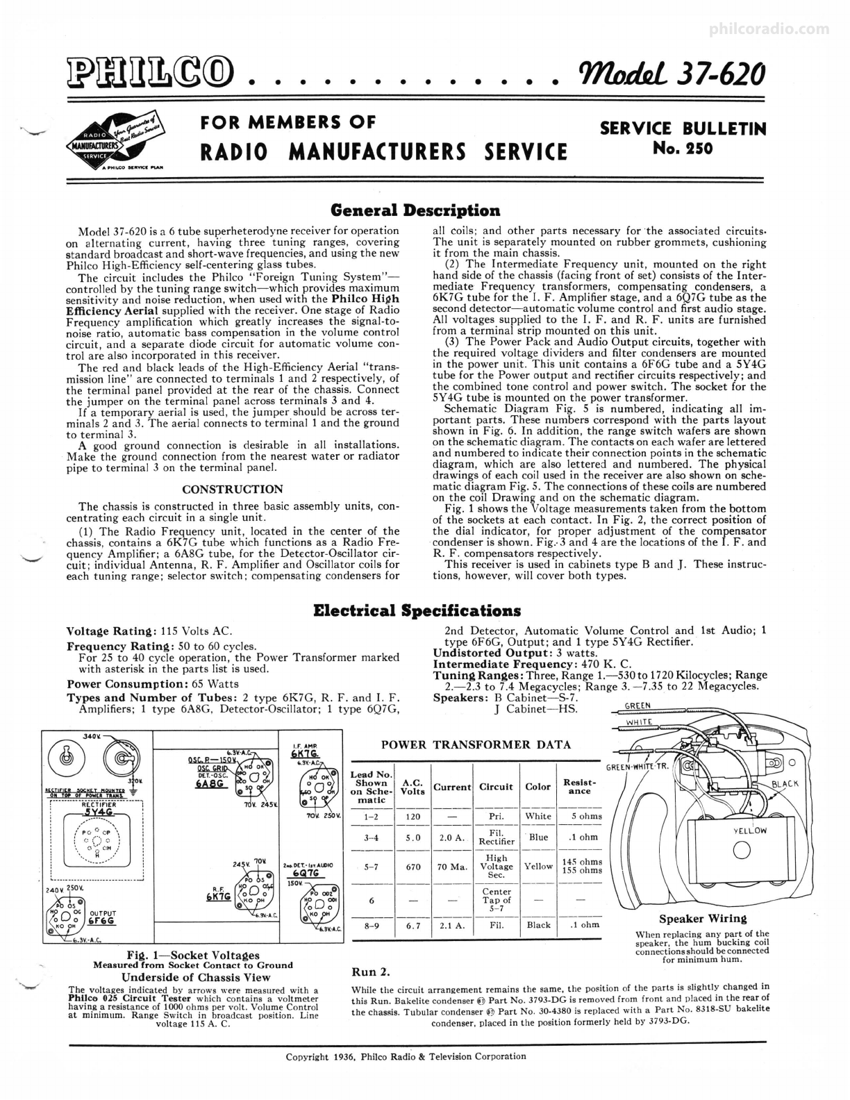
85 PowerTransformer (115Volt50-60 cycle)..... ... •...... ... 32-7583
• Power Transformer (115V;25-40cycle).... ....... .. .. ...... 3S-7584
88 Pilot Lamp. .. .. .. .. .. .. .. .. .. .. .. .. .. .. .. .. .. .. .. .. .. .. 34-2039
87 Condenser(.015-.015mfd. DoubleBakelite)...... , .• .. . . .. . . 3793DG
88 WaveSwitch Antenna.................................... 42-1170
89 Wave Switch R. F.... .................................... 42-1171
70 WaveSwitch Osc.... .. ....................... .. ........... 42-1172
Wave SwitchIndexingPlate & Shaft .... ................... 42-1173
Pilot.Lamp Assembly... .. .. .. .. .. .. .. .. .. .. .. .. .. .. .. .. . 3S-7706
Dial.... .. .. .. .. .. .. .. .. .. .. .. .. .. .. .. .. •.. •.. .. .. •.. . .. 27-5203
Dial Hub.. .................... .. ........ ... ........ ... . 2S-7187
~i:l~~bti·&"r~;.::.·.·::::::::::::::::::::::::::::::::::W:i:i
Dial Gear...... ... ...................... . .. ... ........ .. 2s-7185
DialGuard......... .. .... .... .. .... .................. .. 27-8324
Thrust Spring.... .. .. •. .. .. .. .. .. .. .. .. •. .. .. .. .. ••.. .. . 2s-8611
Thrust Washer..... .. ...... .. ... ........................ 2S-S976
"C" Washer
...... ... .. ........ .. .............. . .. ... .... 2S-S904
Drive Gear........ . .. .. .............. . .................. 31-1884
VernierDrive.... .................. ..... . ............... 31-1871
Mask......... ...... .. ........ .... ...... ................ 27-5198
Mask ArmAssembly..... .. .................... .... ...... 31-1866
Mask Guideon Lamp Bracket Support.......... .. •. ..... . . 2S-7844
Mask WMher.. .. .. .. .. .. .. .. .. .. .. .. .. .. .. .. •. •. .. .. .. . 27-8318
Dial ScreenABBem.. ........................ ............. 3S-7912
tt~g·.·..··:::::::::::::::::::::::::::::::::::::::::::::;~i~
Volume ControlShaft.... .......... .. ........ .... ........ 2S-6499
VolumeControl Shaft Spring.... ... .. ...... ... ............ 2s-4117
Retaining Clips.. .. .. . .. .. .. .. .. .. .. .• .. .. •. ••.. .. ..•. .. . 28-8610
W&Bhcr.......... .. .......... .... .................. ..... 28-4186
Socket8 prong...... .. ..... ... ... :.. .• .. .. .. .•.•.. .. .. .. 21-6058
~':~e§ii:{J' .ng:·.:::::: :: : :: : : :: : : :: : : :: : : ::::::: : :::: : : :
;t~~~
Tube Shield Base.. .. .. .. .. .. .. .. .. .. .. .. .. .. .. .. .. .. .. .. 2S-S898
I. F. Shield..................... . ..... .............. .... 3S-7763
Terminal Panel I. F. Unit ............ . ........ . ...... . .. . 3S-7703
W&Bher I. F. Unit ......... .. ...... .. .... .. ........ . . ..... 2s-4001
Wiring Panel.. .. .. .. .. .. .. .. .. .. .. .. .. .. .. .. .. .. .. .. .. .. 3S-6306
WiringPanel PowerUnit .................... .... , ... ..... 3S-5864
Grommet Mtg. Tuning Condenser.. . .. •. .. .. .. .. .. .. .. .. . 27-4325
Grommet R. F. Unit .............. .. .... .. ....... . ...... . 27-4317
SleeveMtg. R. F. Unit ..... .. .... .... .... ..... .. . ........ 28-2257
SpacerMtg. R. F. Unit ............ .... ................ ... 27-8339
ScrewMtg. R. F. Unit............ . .. . . .. ... .. ...... . .... W-729
WMher Mtg. R. F. Unit.. .. ...... .. .. ...... .......... 28-3927
Insulator, Mtg. Elect. Cond....... .. •. .. .. .. .. .. .. .. .. 27-7194
Bracket Mtg. Elect. Cond.. .. .. . .. .. •• .. .. .. .. .. .. .. . . 6440
Antenna Panel. .. .. .. .. .. .. .. .. .. .. .. . . .. .•. . .. .. .. .. . 3S-7714
Speaker Cable...................... .. .. .. ,........... ... L-2181
A. C. Cord....... .. .. .. .. .. .. .. .. .• .. .. .. .. .. .. .. .. L-2183
Speaker S7-B. Cabinet.. . ... .. .. .. .. .•.. .. .. .. 3f>.1009
t:teT~:i~~--~~~~~~t:.·:.::::::~:::::::·:~:::::::::....:tliig
Knobs Tuning Vernier........ ..... . .. .. .. .... .. .......... 27-4331
KnobsWaveSwitch.. .. .. .......... . ................ ..... 27-4326
Knobs Tone & Volume............. .. ........ ...... ..... 27-4332
BezelFrame & Plate ABBembly.. . .. .. .. .. .. .. ••.. .. .. .. . . 40-5939
G&Aket ...... ........ .............. ... , .. .. •. .. .. .. .. .. . 27~8311
GlaSB.. .. . .. .. .. .. .. .. .. . .. .. •.. •.. .. .. •. .. .. .. . 27-8298
Ring... .. .. .. .. .. .. .. .. .. .. .. .. .. .. •. •. .. .. .. . . 2S-3967
ScrewBezelMtg...................... .. ..... , .. .. .. .. .. . W-1644
Nut Mtg. Volume& Tone Control............. . . W-684
ChaSBisMtg. Screw.. . .. .. .. . . .. .. .. .. .. .. .. .. .. .. .. .. W-1358A
ChMBisMtg. Washer...... ... .. .. .. .. .. .. .. .. .. .. .. 28-2089
Price
List
$0.30
4.50
.15
.40
1.10
1.00
1.10
.50
.35
.50
.12
.10
.02
.10
.02
.01
Per C .30
.01
.26
.75
.30
.35
.15
Per C .50
.30
Per C .50
.02
.10
Per C .40
.03
Per C .75
.11
.11
.10
.03
.20
.25
Per C .25
.03
.02
.02
.04
.01
Per C .40
Per C .45
.01
.01
.05
.15
.26
.40
5.75
6.25
.10
.10
.10
.10
.75
.01
.o.s
.35
Per C .50
Per C 1.25
Per C 2.60
Per C .30
Prlcea Subject to Chanae Without Notice Printed in U. S. A.