No. 310 PHILCO Service Bulletin Page 2
Replacement Parts Model 39-116
Sclwm.
.!\o. De:-inlp tlon Part No.
I
2
3
4
5
8
7
8
9
10
II
12
13
14
15
16
17
II
19
20
21
22
23
24
25
26
27
28
29
30
31
32
33
34
35
38
37
38
39
40
41
42
43
44
45
48
47
48
49
50
51
52
53
54
55
58
57
58
ff
ea
81
82
83
14
85
..
87
..
..
70
Anlenn• T... n,rormer (BC! ........ . .. .. . . . 32-30:;6
Antenna Translormer (l'olh-e) . ... .. •... . .. a:t-3U53
Antenna Tran sforme r (S. W.) . .... ..... . .. . 3;l-3055
l'omi;enut or Antenn• Shortwave ..... . ..... 31-6212
~
~1~
~~~
Ytrtiise:in\i~½
1
~~itti::::::::::::~g:~~rn39
lle slslor (2.0 meg.-'h wall! . .. . .. . .. . . .. . 33-520339
Tubuhtr Condenser (.1 mfd.) .......• ••. . . . 30-4455
i~;t~:!;~1i~~ff0;~~;t:::::::::::::Uillij
39
H.1''. Tunsrormer (Po lke) ..... . . • ...... . . 32-3054
R.F. Tnn: ;form er (S .W .) ..... .. .. . ........ 32-3046
~llc-11.Con<.lenser (5 mmfd.) .•.••••..• • • •• • .• 30-1097
Com1,en~ator R.F. Shortwne .... . .... . . . ·- . 31- ti:lU
Tubular Condense r (.05 mfu.) ......... ... . 30-4519
Resistor (51,000 ohm-½ wall) ...... . . . .. . 33-3" l339
g::rn:1:r
i~~~
~~~~::~
~~~fi/e,<,~~~::::::::~t5t~g
Osc-11111.tor Tran sformer (S.\V.) ..... . ..... .. 32-3051
Compensato r Strip (oscillator) . .... . ... .. .. 31-6266
Compen sator Broatlt •as~ Low Frequ enry . . . . . 31-6230
Condenser Sem1-ftxetl (1230 mmM.) . . . ... .. 31-6262
Condenser Semt-ftxed (342:i mmftl . ) ...... . • 31-6263
)fka Condenser (250 mmfd .) . . . .......... . 30-1032
lleslstor (32,000 ohm-½ watt) . ....... . ... 33-332339
Resis tor (10,000 ohm-½ wall) ............ 33-310339
t:::1~;iitxxx~~::;=! ~:m::::::::::::iJ:gm~:
Ele<·trolytlr Conden ser (4 mftl.-250 Y .) .... 30- 2334
l\llca Conden ser (250 mmftl.) . . . . . . . . . . . . . . 30-1031
1st I F .. Tran sformer Assembly ..... . . . . .. , . 32-3089
Tubular Condenser (.01 mfd.) ...... . .. ...
~
30-4572
Resis tor (1.0 rnea:.-¼: watt) .... .. . . .... .. 33-!i l03 39
Resi stor (330.COOohm-½ watll .... ... .... 33-433339
Resistor (330.000 ohm-½ watt) . .......... 33-433339
?.nd I.F . Trando rmer Assembly ... . . . . .. . .. 32-2645
Min Condense r (110 mmfd.) ... . . . ... . . . 30-10 31
Tubular Condenser (.01 mfd.) ............. 30-4479
Min Condenser (50 mmfd .) ...... . . . ..... . 30-1029
Yolume Contr ol . .. . . ................. . ... . . 33-5300
Resistor (70,000 ohm-•,. waU ) .. ... . . . . . . . a3-3 70339
Tubular Condenser ( 004 mfd.) ..... . .... .. 30-4334
Resisto r (2.0 meg,-½ wall) .. .. .. .. ... . .. 33-52 0339
Tubular Conde nser (.015 mfd .) .. . ..•.. . ... 30-4:i29
Resistor <J.O meg.-1, walt) . . . .. . . .. ... . . 3a.51oa39
Tubular Condenser (.1 mftl .) . . . . .. .. . . .. .• 30-4:i27
Resis tor (99.0 00 ohm-½ wall) . ... . . . • .. .. 33-3!19339
Tubular Conde nser (.01 mid. l ............. 30-41 69
Resistor (490.000 ohm-•,. watt) ........... 33-449339
Resistor (!i.000 ohm-% watt) ... . ... . . .... 33·250339
Resistor (45,000 ohm-½ watt) ... . . . .. .. . . 33-345339
Tubula r Conde nser (.02 mfd .) ........ . .... 30-44 81
Tone Contr ol (3 mer.) .. .. . . .... ... .. .. ... 33-5287
Tubular Conden ser (.01 mfd. ) . .... . ... . ... 30·4572
Tubular Conden ser (.01 mid.) ........... . . 30-4572
Rea18tor ( 51,000 ohm- ½ watt) . . ... .. .. . . 33-351339
Restator (490.000 ohm-½ wall) ... .. .. . ... 33-449339
Resistor (490,000 ohm-½ wall) ... .... .. .. 33-4 49339
Resistor (240.000 ohm-½ watt ) . . . . . .... . . 33-424339
Tubular Condense r (. 1 mfd.) .... . . .. . .• .. . 30-449 9
Tu bular C'ondenaer (.01 mfd.) . ........ . ... 30-4501
Output Tra nsfor-mer ... .. ... . . . ... . . . .. .... 32-7998
Voice Coll & Cone Auembly (Speaker No.
36-1450) . ......... . .... . ....... .... .... 36-4089
Tubular Condense r (.01 mrd.) . . ......... . . 30-4501
Re sisto r (3.000 ohm-½ watt ) . . . .. . . .. , . . . 33- 230339
Resi stor (1.0 mee.-½ watt) . . ... . ... . .... 33-510339
Eleclrolytt c Condenser (25 mld .-300 V. ) . . . 30- 2360
Ele clr olytlc Condense r (18 m!d .-475 V.) .. . 30-2200
S<.·ht>m.
No.
71
72
73
74
75
78
77
78
79
80
81
82
83
14
85
88
87
88
89
89A
89B
89C
89D
89E
89F
896
89H
90
90A
11GB
90C
90D
BOE
90F
906
90H
91
92
93
94
95
96
97
98
99
100
101
102
103
104
105
108
107
108
109
110
111
112
113
114
115
Ill
117
Ill
119
120
121
122
123
De s!'rlptlon
Field Coil (Replal'e Speaker No. 36- 1450) . .
Re sistor (Wirewound-Bias) ...... . ..... . . .
Power Transformer (11 5 V.- 50 to 60 <·yt•les).
Power Trans. (115 V.-25 to 4U 1•yt•lell)....
Bypai;s Condenser (.O.:,mfd,) (110 V. ptue) .
Pilot Lamp (Bullseye) . .. . . .. .... .. ... .. . .
Pilot Lamp Heust or (16 ohm) . . ... . , .... . .
PIiot Lamp s (Dial) ........ .. . ... .. . .. . .. .
Filament Trans . (115 V.-50 to 60 cyc les) . .
Filament Tnns. (115 V.-25 to 40 cydes) ..
Motor Trans. (115 V.-50 to 60 ey<:les)... .
Mctor Trans. (115 V.-25 to 40 cyr les) .. .. .
Motor (Volume Control) Assemb ly . . . .... . .
llotary Swlt<·h (Stepper Unit) . . ..•..••. .. •
B.C. Resis tor (10 ohm) Wirewound ... .. ... .
Pilot Lamp Assembly (Statton Indicator) . . .
Switc h (Volume Control-l lotor) .. .. .. ..•. .
Resistor (150 ohm-% watt) . . .. .. ........ .
TubuJar Condenser (.1 mfd .) . .. . . . ...... . .
Tubular Conclenser (.1 mflt .) . ... ., .... . . . .
Electrolytic Condenser (30 nifd .-3 0 V.) .. . .
Push Button Packler Unit .... . ... . . .. . . .. .
CompensatorNo. l ( 540-1030K.C . ) P artof89
Compensator No. 2 ( 540-103 0K .C.) Partof89
Compensator No. 3 ( 670-116 0K. C.) Partol89
CompensatorNo. 4 ( 670-1160K.C .) Partol89
Compensator No. 5 ( 900-1470 K.C.) Part of 89
Compensator No. 6 ( 900-1470 K. C.) Part or 89
CompensatorNo. 7 (1100-1600K.C.) Partol89
Compensator No. 8 (1100-1600 K.C.) Partol 89
ElectrJc Push Button Tr ansform er Assemb ly
Part No.
33-3364
32-8001
~2-8017
30-4576
34-2210
33-016431
34-2004
32-7993
32-80 16
32-799 0
32-8015
35- 1151
42-1468
33, 3363
34-2064
42-1469
33-115339
30-4499
30-4499
30-236 1
31-626 4
(8 Trans .) .. . .... . .............. .. ..... 32-3091
OscUlator Trans . No. 1 ( 540-1030 K .C. ) . ... 32-3042
Oscillator Tran s. No. 2 ( 540-10 30 K.C . ) .... 32-3042
Oscillator Trans . No. 3 ( 670-1160 K.C . ) . . . . 32-3042
Osrtllalor Trans. No. 4 ( 670-IHIO K .C.) .. .. 32-3042
Osctllalor Tran s. No. a ( 900-1470 K.C . ) . . .. 32-3041
Osctllalor Tran s. No. 6 ( 900-1470 K.C.) .... 32-3041
Oscillator Tran s. No. 7 (1100-1600 K.C .) .. .. 32-3041
Osctllator Trans . No. 8 (1100-1600 K. C.) . .. . 32-3041
Silver Mlca Condenser (370 mmfd.) . . .... .. 80-1110
Sliver Mica Condenser (370 mmftl) .. . . . . .. 30-1110
Bakelite Condenser (.05 mfd.) . . . . . . .... .. . 3615-SG
Resist or (150 ohm) .. . .. .. . .. .. .. .. . .. .. .. 33-3362
Electrolytic Condenser (16 mr,1.-200 V.) .. . 30-2356
Cho'<e Coll .. . ... .. .. . .. . . .... . . . .. ... .. . 32-1281
Tubula r Condenser (.05 mfd.) . .. .. ... ..... . .. 30-4123
Tubular Condenser (.05 mid.) . .. .. . . .. . : . .. 30-4113
Tubula r Condenser (.1 mfd.) . . . . . . . . •• . . . . . 30-4499
Tubular Condenser (.5 mfd.) ........ .. . . ... 30-4551
Resistor ( 4.000 ohm--'-½ wait) . .... .. . . . . . 33-240339
Resistor (51.000 ohm-½ watt) . . .. .. ... . .. 33-351339
No. 3 Control Amp_ Transformer .. . . . ...... 32-3088
Tubular Condenser (.02 mfd . ) : ............ 30-4516
Mica Condenser (550 mmfcl.) .. . .. ... . • •. ... 30-1092
Resistor (750,000 ohm-½ wall) ... .. . •... . 33-475339
Resistor (1.0 meg.-1, watt) . ... .. ... , . ... 33-510339
Resis tor (99,000 ohm-½ wall) ... .. . . . . .. 33-399339
Tubular Condenser (.05 mid.) ...... . . ..... 30-023
Resistor (99,000 ohm-½ wall) . . . ... .• . . .. 33-399339
Tubular Condenser (.05 mid.) .... .. . ... .. . 30-4123
Tubular Condenser (.05 mid .) ........ . .... 30-4444
Resistor 0. 5 mer .-½ watt) . . . . . . . . ... .. . 33-515339
Tubular Condenser ( 05 mfd .) . . .. .... .... . 30-4519
No. 2 Control Amp. Tran sformer . . . . . . . . . . . 32-3087
Tubu lar Condenser (.05 mid .) . . . . .. . . . . .. • 30-4444
Renstltvlty Control . . . . .. . .. .. . .. . . .. .. .. . 33-5295
Reslal01' (300 ohm-¼ watt.). . .. .... . .. .... 33-130339
No. 1 Control Amp . Transforme r .. ... . .. , . . 32-3086
Sllrer Mira (200 mmld.) .. . . ... .... . .. . ... 30-1122
Compensator {Se<-ondary lnduetor ) .. . .... . . 31-62fi8
!le<ondary Inductor (Mystery Tunlnc) . .. ... 40-6415
Wave Switch ..... .... ..... ... ........... 42-1451
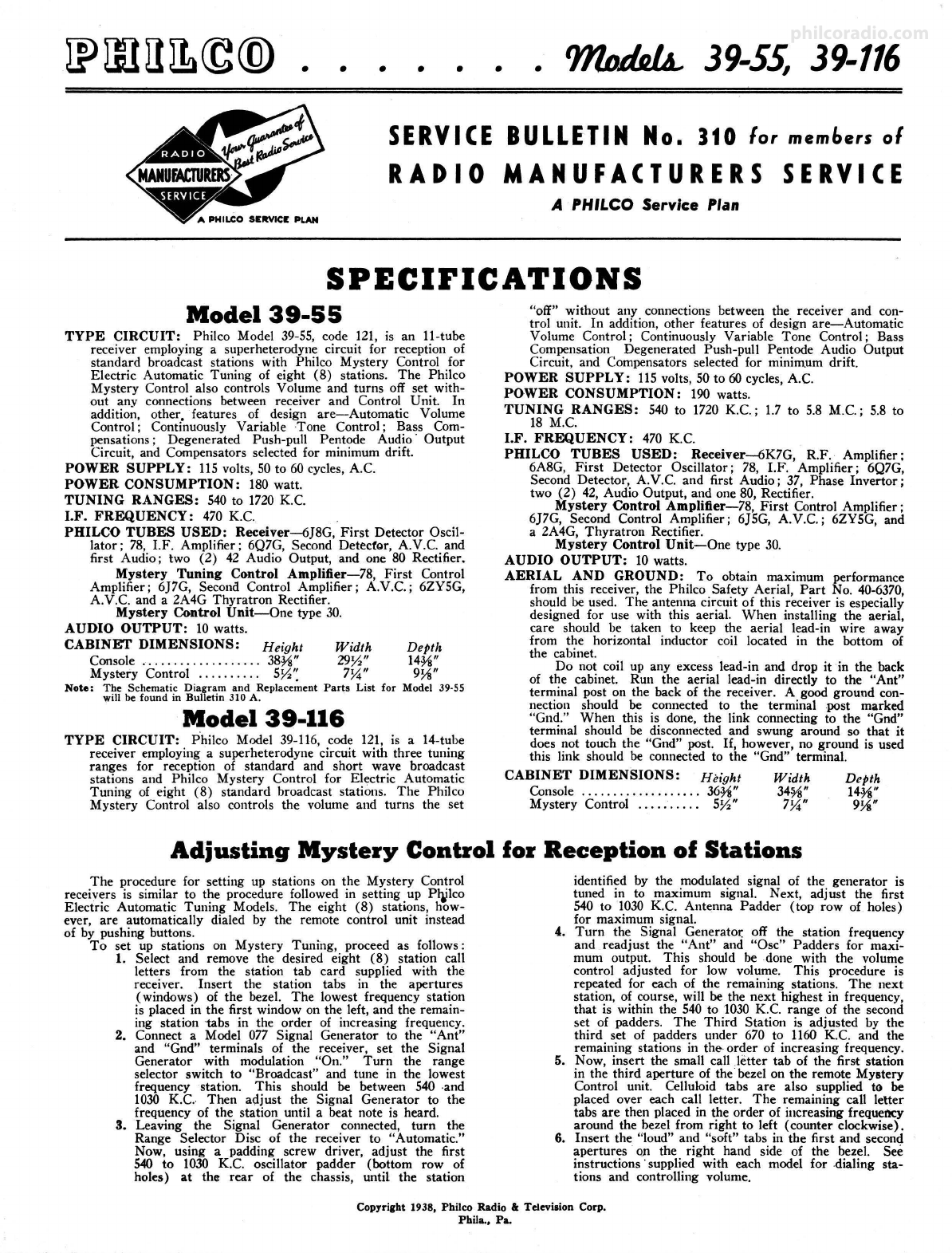
Mystery Control Unit
Schem .
No.
124
125
128
127
128
129
130
Descrlptlon
l'rima t·Y Induc tor . . .... . ..... . . .• • • .... . .
Stiver )flu Conll. .. .. .. . . . ...... •• . . . .. ..
Air 1-'adder .. . ... . .... . ....•....•• . . . ... .
Tubular Cond. (.05 mt.) ...•.. . .. . .. . . . .. ..
Resistor (MO ohm,-½ wall) ...... . . . ... . .
l\lystery l'ack . . .. ....... .. . .. . . . .. .... . . .
Dial Un ll (Pulser) , .. ......... . . . .. . .... .
Miscell&neoas Parts
Part No.
32-3097
30-1115
31-6288
30-4519
33-150339
41-8016
38-9704
Bezel AHembly (Cabinet) .. . ......... ... . . 38-9732
Bezel Screws- . . . . . . . . . . . . . . . . . . . . •. . . . •. . W •1885
Cable (Tuntnr Drum) ....... .. . ... ... . .. . Sl -2315
Cable (Pointer) . ....... ... ...... . . .. . . .. . 31-2320
Dial . . .. .. .. . .. . .. .. .. .. .. . •. . • .. .. .. .. . 27-5428
Dial Point er . . . .. .. • . .. . .. . . . .. • ..... . . . . 56· 1033
Disc (Tuntnr) ... .. .. .... ... . .. ....... . ... 27-4768
Disc (Volume) . .. .. ...... .... ... .. .. .. . .. 27-4765
Disc (RallJle Switch) . ......... .. ....... .. . 27-4767
Disc (Tone Control) .... ... .. .. .. . .. . .. . .. 27-4764
Pflol J,amo Assembly ....... . ...... ... .. . . 38-9694
.Pilot Lamp Assembly (Dial) ......... .. .. 38-9711
Pilot Lamp Assembly (Tabs) . . .. . •, •.. . .. 38-9712
Socket (4 prong) ........ ....... ......... . 27-6044
Socket (5 prong) ..... . ....... .. ..... .. .. . 27-603,
Socket (6 prong) .................. ... .... 27-6036
Socket (7 pronr) Octal. ................ .. 27-6057
Socket (6 prone! Octal. . ... . .. . •.... . . . . . 27-60811
Socket (7 prong) Octal. ........ .. .... . ... 27-6099
Speaker .. .. . . . . . .. .. . .. . .. . .. .. . .. .. . .. 36-1450
Rorlng (.Tuning Cables) . . ..... .. . . . . .. .. .. 28-8913
Washer (Keyed Washe r Tunlna Dl ac) . ..... 58-1029
Washer (Spring Washer Tunlna Disc ) ... . .. 6717
Mystery Control Unit
t::I &;e~s·::::::::::::::::::::::::::::
Cap Tuning Disc .. . . .. •. .. . . .. • .•... .... .
Disc (Tunlnr) ...... .. . ...... . .. . .. .. .. . .
Pulser Assembly . . . ... ... . . .. .•••... .. . . .
Stop (TunlllJI Disc) .... ... ... , .......... .
Socket 14 prone ) ............. . ...... .. .. .
Screw (Ftn1er Stop) ............ . ...... . ..
Spacer (FlllJler Stop) ...... .. ........... . .
56-1140
W-2138
27-4793
27-4792
38-9704
27-4794
27-8119
W-2139
27-4195
Mystery Control Unit Diagram
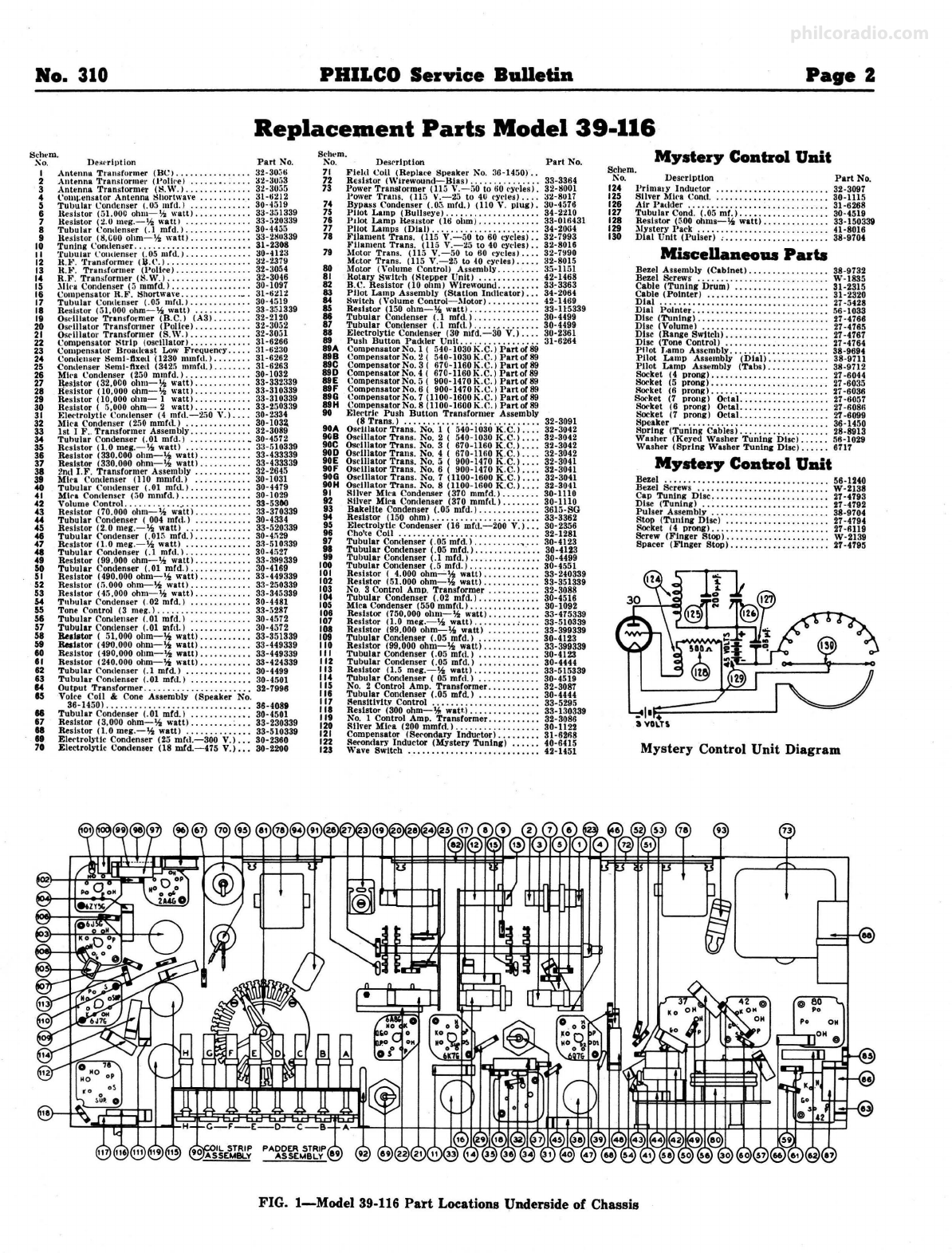
FIG. 1-Model 39-116 Part Locations Underside of Chassis