manuals.online logo
Brands
  1. Home
  2. •
  3. Brands
  4. •
  5. Philco
  6. •
  7. Radio
  8. •
  9. Philco 650 User manual

Philco 650 User manual

PHILCO
I... U.S.PAT.OfF.
Service Bulletin No. 2.20
Model 650
Type Circuit: Superheterodyne, with preselector R.F.
amplifier, and push-pull pentode output (10 watts); built in
connections for Philco All-wave aerial; aerial selector built
into and operated by wave-band switch.
Power Supply: Alternating Current. Voltage and fre-
quency as specified on chassis nameplate.
Tubes Used: 1 type 78, R.F.; 1 type 6A7, Detector-
Oscillator; 1type 78, l.F.; 1type 75, 2d Detector and 1st A.F.;
1 type 42 Driver; 2 type 42 Push-Pull Output; 1 type EO
Rectifier.
Wave Bands: Four: (l)Long-wave (U.S.Weather Forecasts);
(2) Standard (with some Police); (3) Police; (4) Short-wave.
Coverage of Each Band: Band 1, 145 to 390 K.C.; Band 2,
540-1720 K.C.; Band 3, 2.2 to 2.6 M.C.; Band 4, 5800-18000
K.C. (5.8 to 18.0 megacycles).
· Tuning Drive: Dual planetary, ball bearing. 80 to 1
ratio for slow-speed tuning.
Tone Control: 4-position, with bass compensation effective
in first position (counter-clockwise).
Intermediate Frequency: 460 K.C.
Power Consumption: 98 watts.
Speaker: 650B (Code 121); K-17, 650X, 650MX, 650-H,
(Code 122); H-13.
Tube Socket Voltages (Line Voltage 115)
Measured to Ground
78 6A7 78 75 42 42
Tube R.F. Det. I.F. 2d Driver Out-·
Osc. Det .. put
Point
p 55 200 200 115 200 300
---
SG 90 90 90 .'' 200 300
--- ---
K 2.2 2.3 2.6 . .. ... . . '
6A7:Gu,=155
Above voltages were obtained by using a PHILCO type 025
Circuit Tester (or 048A All-purpose Tester), using test prods
applied to underside of chassis. Volume control at minimum;
dial at 55; waveband switch counter-clockwise (band 1). Use
Fig. 1 for test points. Type K-17 speaker employed.
ITT
er
80
RECTIFIER.
78
I.F.
Fig. 1. Tube Sockets as viewed from bottom.
Power Transformer Data
Term- A.C. Current Circuit Color
inals Volts
---1-2 120 ...... Primary White
---3-5 760 140 M.A. Secondary Yellow
---6--7 5.0 2.0 A. Fil. Rect. Blue
---8-9 6.3 3.75 A. Filaments Black
4 ... ...... Center Tap of Yellow, Green
3-5 Tracer
Adjusting Compensating Condensers
Fig. 2. Locations of Compensating Condensers
Adjustment of compensating condensers in Model 650
requires an accurate signal generator covering long-wave,
standard wave, police, and short-wave frequencies. The
PHILCO Model 088 All-Wave Signal Generator, having a
continuous range of from 100 to 20000 K.C., is ideal for this
purpose.
An output meter is also needed. PHILCO Model 025
Circuit Tester includes a high grade output meter.
Philco No. 3164 fibre wrench and No. 27-7059 fibre-handled
screwdriver complete the equipment needed for making these
adjustments. The locations of the various compensating
condensers is shown in Fig. 2. Connect the output meter to
the plate contacts of the 42 output tubes (using the adapters
provided with the "025") and set it at the 0-30 volt range.
I.F.-Set the Signal Generator at 460 K.C., and attach its
antenna lead to the grid cap of the 6A7 tube on the Model 650
(having removed the grid clip from the tube). Connect the
ground terminal of the Signal Generator to the ground term-
inal of the set. Turn on the set, turn the waveband switch to
second position (standard) and set dial at 55. Now with the
fibre screwdriver, adjust condensers @ and @ (2d I.F.)
and then @) and @) (1st I.F.) until maximum reading is
obtained in the output meter. Turn down the "attenuator"
on the signal generator if the output meter needle goes off the
scale.
philcoradio.com
+
~
w
,rR.r.------~- ---,'ofi.-osc.-7
~-w,' I ,
I
• n .. '
~
... ,v @..uoµµf /;'1\
~" I ' 4
~
~-@
' W-:' - ,__,'-' c; -J._1.231'1
~
~
4--
~
2,0MEG-. TOT~8 '=" 1 IA\. 8 :L
.-@ TAPAT +00,0001\~'
~
; &~, 6 J~
. i\ 1... I'):)
58.1= r~oo.n.. l:I ~J.1@
~
~?ijY
", ', ' '
- o.o~..f L'flI l I
~
1~~
ffi.
~,~
)ca .• :::, I • n..... - ' ~-c©: I
-'=" I&- . . . . ..---- ~--
' '
--1 -1 a•,+ - I I •
------_____,~
~
y i,~
-: - 4--
~
-.,-.,
,.,r_
✓,;;:\
@Ti+rJ:~+1~
@ ®
NUMBERSINDICATERELATIVEPOSITIONSOF SWITCH
SECTIONSFROMFRONTOf'CHAS!ltS
Fig. 2. Schematic Diagram of Model 650
,, ',,
6 000t'l'f
.-,•-·-.,
~►-,
)¾
~~
I~
~
®
~,®
:'...'.;?
II-®
~--:f;,~
@· -,,·@ .,,f
q..
___ _j@t!
¾
2 3
6o
~
ALL SWITCHSECTIONSSHOWN
o IN POSITIO_NN0.4
I.F.=460 KC.
"C
::.,
(Jo.
CD
~
00
~
:a,,
n·::c
~-
o::ir-
~n
;:o
t"'I-
....
::s
z
0
~
~
=
philcoradio.com
No. 220 PH I LCO
Service Bulletin Page 3
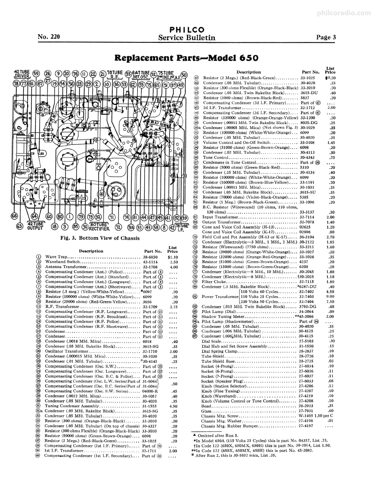
Replacement Parts--Model 650
Fig. 3. Bottom View of Chassis
Description Part No.
Wave Trap .••........•. ,.,., .......... , ...... 38-6850
Waveband Switch ...................... ,., .... 42-1114
Antenna Transformer .......................... 32-1708
Compensating Condenser (Ant.) (Police)....... . . Part of @
Compensating Condenser (Ant.) (Standard) . . . . . . Part of @
Compensating Condenser (Ant.) (Longwave).... . Part of @
Compensating Condenser (Ant.) (Shortwave) ..... Part of@
Resistor (.5 meg.) (Yellow-White-Yellow) ........ "'6097
Resistor (100000 ohms) (White-White-Yellow) .... 6099
Resistor (25000 ohms) (Red-Green-Yell ow).. . . . . . 3656
R.F. Transformer ............................. 32-1709
Compensating Condenser (R.F. Longwave) ....... Part of@
Compensating Condenser (R.F. Broadcast) ....... Part of@
Compensating Condenser (R.F. Police)... . . . . . . . Part of @
Compensating Condenser (R.F. Shortwave)... . . . Part of @
Condenser. . . . . . . . . . . . . . . . . . . . . . . . . . . . . . . . . . . Part of @
Condenser. . .. .. . . . . . . . . . . . . . . . . . . .. . .. .. • . . . Part of @
Condenser (.0018 Mfd. Mica) ..... ,... . . . . . . . . . . 6018
Condenser (.05 Mfd. Bakelite Block) ............ 3615-SG
Oscillator Transformer ......................... 32-1710
Condenser (.000015 Mfd. Mica) ................. 30-1030
Condenser (.01 Mfd. Tubular) .................. #30-4145
Compensating Condenser (Osc. S.W.)......... . . . Part of @
Compensating Condenser (Osc. Longwave)...... . Part of @
Compensating Condenser (Osc. B.C. & Police) .... Part of@
Compensating Condenser (Osc. L.W. Series)Part of 31-6044}
Compensating Condenser (Osc. B.C. Series)Part of 31-6044
Compensating Condenser (Osc. S.W. Series) ...... 04000-R
Condenser (.0022 Mfd. Mica) ................... 30-1057
Condenser (.05 Mfd. Tubular)...... . . . . . . . . . . . . 30-4020
Tuning Condenser Assembly ................... 31-1555
Condenser (.05 Mfd. Bakelite Block).... . . . . . . . . 3615-SG
Condenser (.05 Mfd. Tubular) .................. 30-4020
Resistor (300 ohms) (Orange-Black-Black) ....... 33-3010
Condenser (.05 Mfd. Tubular) (On top of chassis) 30-4327
Resistor (300 ohms Flexible) (Orange-Black-Black) 33-3010
Resistor (50000 ohms) (Green-Brown-Orange) .... 6098
Resistor (2 Megs.) (Red-Black-Green) ....•....• , 33-1025
Compensating Condenser (1st I.F. Primary) ...... Part of@)
1st I.F. Transformer .......................... 32-1711
Compen•atin11; Condenser (1st 1.F. Secondary) .... Part of 0.0
List
Price
$1.10
2.50
4.00
.20
.20
.20
3.15
.40
.35
3.00
,35
.25
.so
.45
.40
.35
4.50
.35
.35
.20
.20
.20
.20
.20
2.00
Description Part No.
@ Resistor (2 Megs.) (Red-Black-Green) ........... 33-1025
@ Condenser (.05 Mfd. Tubular)... . . . . . . . . . . . . . . . 30-4020
(§1 Resistor (300 ohms Flexible) (Orange-Black-Black) 33-3010
@ Condenser (.OS Mfd. Twin Bakelite Block)...... . 3615-DU
@ Resistor (1000 ohms) (Brown-Black-Red) ........ 5837
(<'!) Compensating Condenser (2d 1.F. Primary) ...... Part of@
@ 2d 1.F. Transformer ........................... 32-1712
(~ Compensating Condenser (2d 1.F. Secondary) .... Part of@
@) Resistor (330000 ohms) (Orange-Orange-Yellow) 33-1200
@) Condenser (.0001 I Mfd. Twin Bakelite Block) ..... 8035-DG
@)a Condenser (.00005 Mfd. Mica) (Not shown Fig. 3) 30-1029
@ Resistor (100000 ohms) (White-White-Orange) ... 6099
@ Condenser (.05 Mfd. Tubular) .................. 30-4020
@ Volume Control and On-Off Switch .............. 33-5108
@ Re•istor (51000 ohms) (Green-Brown-Orange) .... 6098
@ Condenser (.02 Mfd. Tubular) .................. 30-4113
ITone Control. ................................ 30-4343
58
57 Condensers in Tone Control...... . . . . . . . . . . • . . . Part of @)
Resistor (5000 ohms) (Green-Black-Red) ......... 5310
@) Condenser (.25 Mfd. Tubular) .................. 30-4134
@) Resistor (100000 ohms) (White-White-Orange) ... 6099
@ Resistor (160000 ohms) (Brown-Blue-Yellow) ..... 33-1191
@) Condenser (.00011 Mfd. Mica) .................. 30-1031
@ Condenser (.05 Mfd. Bakelite Block) ............ 3615-SU
@ Resistor (70000 ohms) (Violet-Black-Orange) ..... 5385
@ Resistor (I Meg.) (Brown-Black-Green) .......... 33-1096
@) B.C. Resistor (Wirewound) (10 ohms, 110 ohms,
130 ohms) .................................. 33-3137
Input Transformer ............................ 32-7114
Output Transformer .......................•... 32-7078
Cone and Voice Coil Assembly (H-13) ........... 02625
Cone and Voice Coil Assembly (K-17) ........... 02996
@) Field Coil and Pot Assembly (H-13 or K-17) ..... 36-3104
@ Condenser (E!ectrolytic-3 Mfd., 1 Mfd., 2 Mfd.) 30-2122
@ Resistor (Wirewound) (7750 ohms) .............. 33-3211
@ Resistor (39000 ohms) (Orange-White-Orange) ... , 33-1027
@ Resistor (32000 ohms) (Orange-Red-Orange) ..... 33-1026
IResistor (51000 ohms) (Green-Brown-Orange) .... 4237
6 Resistor (15000 ohms) (Brown-Green-Orange)... . 6208
7 Condenser (Electrolytic-8 Mfd., 10 Mfd.)....... 30-2045
@ Condenser (E!ectrolytic-8 Mfd.) ............... t30-2025
@ Filter Choke ................................. 32-7115
@) Condenser (.3 Mfd. Bakelite Block) ............. *6287-DU
@ Power Transformer 110 Volts 25 Cycles ......... 32-7403
{110 Volts 60 Cycles ......... 32-7402
230 Volts 50 Cycles ......... 32-7404
Condenser (.015 Mfd. Twin Bakelite Block) ...... 3793-DG
Pilot Lamp (Dial)......... . . . . . . . . . . . . . . . . . . . . 34-2064
Shadow Tuning Meter ........................ **45-2086
Pilot Lamp (Shadowmeter)......... . . . . . . . . . . . . Part of @)
Condenser (.05 Mfd. Tubular) ...........•...... 30-4020
Condenser (.006 Mfd. Tubular) ................ 30-4125
Condenser (.006,;Mfd. Tubular) ................ 30-4125
Dial Scale .................................... 27-5103
Dial Hub and Set Screw Assembly ..........•... 31-1550
Dial Spring Clamp. . . . . . . . . . . . . . . . . . . . . . . . . . . . 28-283 7
Tube Shield .................................. 28-2726
List
Price
so.20
.35
.20
.40
.20
2.00
.20
.25
.35
.20
.35
1.45
,20
.30
.75
.20
.40
.20
,20
.35
.35
.20
.20
.30
2.00
1.40
1.20
.90
2.70
1.85
1.60
.20
,35
.20
.20
1.80
1.10
1.80
.40
4.50
9.00
7.50
.40
.09
2.00
.35
.25
.25
.30
.15
.10
.10
Tube Shield Base ...........•................. 28-2725 .03
Socket (4-Prong) .................•............ 27-6034 .10
Socket (6-Prong) .............................. 27-6036 .11
Socket (7-Prong) .............................. 27-6037 .11
Socket (Speaker Plug) . .. .. . . . . . . . . . . . . . . . . . . . . 27-6033 .08
Knob (Station Selector) ........................ 27-4206 .12
Knob (Fine Tuning) ........................... 27-4207 .10
Knob (Waveband) .....................•.. 27-4219 .10
Knob (Volume Control or Tone Control).. . . . . . . . 27-4208 .10
Bezel. . . . . . . . . . . . . . . . . . . . . . . . . . . . . . . . . . . . . . . . 28-2933 .35
Glass ........................................ 27-7931 .60
Chassis Mtg. Screw.. .. .. . . . . .. .. . . . .. .. . . . . . . W-1495 1.50 per C
Chassis Mtg. Washer .......................... 27-4198 .01
Chassis Mtg. Rubber Bumper .................. 27-4197
• Omitted after Run 5.
*In Model 650A (115 Volts 25 Cycles) this is part No. 04357, List .75.
tin Code 122 (650X, 650MX, 650H) this is part No. 30-2014, List 1.50.
**In Code 122 (650X, 650MX, 650H) this is part No. 45-2082.
# After Run 2, this is 30-1032 mica, List .35.
philcoradio.com
Page 4 PH ILCO
Service Bulletin No. 220
WAVE TRAP-Connect the Signal Generator antenna
and ground leads to the antenna and ground posts of the set.
Replace the grid clip on the 6A7 tube cap. With the signal
generator operating at 460 K.C. and the set controls adjusted
as for I.F., adjust wavetrap © until the minimum reading is
obtained in the out-put meter.
SHORTWAVE-Turn waveband switch to position 4
(extreme right). Set signal generator at 18 megacycles and
dial of set at 18.0 (top scale). Now adjust the oscillator, R.F.,
and Antenna compensators in turn, for maximum reading.
These are @),@ and® respectively.
Turn the dial to 6.0 M.C., set the signal generator at 6.0
M.C., and adjust condenser @ for maximum reading. This
compensator is located underneath the chassis and reached
from underneath. (See Fig. 3).
STANDARD WAVE-Turn waveband switch to position
2 (standard broadcast), set signal generator at 1500 and dial
of set at 150. Now adjust the oscillator, R.F., and antenna
"Standard" condensers. These are @, @ and ©
respectively.
Now turn the dial to 60, set signal generator at 600 and
adjust condenser @ (oscillator standard-series) (nut) for
maximum reading.
POLICE BAND-Turn waveband switch to position 3
from left (police band); set dial at 2.4 and signal generator at
2400 K.C. Adjust condensers© and@ for maxmium reading.
(Antenna and R.F. Police.)
LONG WAVE (Weather) BAND-Turn waveband switch
to position 1(left) (Longwave). Set dial at 35 and signal gener-
ator at 350 K.C. Adjust condensers@, @and© (oscillator,
R.F., and Antenna Longwave) for maximum reading.
Turn dial to 17, signal generator to 170 and adjust con-
denser ® (longwave series) (screw) for maximum reading.
PHILCOHeadphoneandAdapterKit
IdealAcce$soryforModel 650
To enable short-wave fans to "listen-in" with
maximum convenience and comfort at any hour of
day or night, without disturbing anyone else in the
room, the PHILCO Headphone and Adapter Kit,
(Part No. 45-1167) fills a long-felt need. Also ideal
for the hard-of-hearing member of the family.
Contains a pair of De Luxe Light-weight, highly
sensitive headphones with cord and plug, and a
special Adapter-box with cord and plug for con-
necting to radio by inserting under tube.
Can be used with practically any radio without
changing any connections. Comes packed in a
neat cardboard box, with full instructions. Philco Headphone and Adapter Kit
Part No. 45-1167
PHILCO Headphone and Adapter Kit, Complete .................. List Price, $7.50
YOURDISTRIBUTORCANSUPPLYYOU
PHILCO RADIO & TELEVISION CORPORATION
Parts and Service Division
May, 1935 Printed in U.S. A,
philcoradio.com

Other Philco Radio manuals

Philco 144 User manual

Philco

Philco 144 User manual

Philco 37-675 User manual

Philco

Philco 37-675 User manual

Philco D-592 User manual

Philco

Philco D-592 User manual

Philco 121 User manual

Philco

Philco 121 User manual

Philco 623 User manual

Philco

Philco 623 User manual

Philco 121 User manual

Philco

Philco 121 User manual

Philco 37-60 User manual

Philco

Philco 37-60 User manual

Philco 37-116 User manual

Philco

Philco 37-116 User manual

Philco 121 User manual

Philco

Philco 121 User manual

Philco 37-660 User manual

Philco

Philco 37-660 User manual

Philco 121 User manual

Philco

Philco 121 User manual

Philco PRR1005BT User manual

Philco

Philco PRR1005BT User manual

Philco 77 User manual

Philco

Philco 77 User manual

Philco PHOTOFACT 49-1150 User manual

Philco

Philco PHOTOFACT 49-1150 User manual

Philco 37-640 User manual

Philco

Philco 37-640 User manual

Philco 121 User manual

Philco

Philco 121 User manual

Philco 200 User manual

Philco

Philco 200 User manual

Philco 29 User manual

Philco

Philco 29 User manual

Philco 643 User manual

Philco

Philco 643 User manual

Philco 37-650 User manual

Philco

Philco 37-650 User manual

Philco 15 Series Reference manual

Philco

Philco 15 Series Reference manual

Philco 66 User manual

Philco

Philco 66 User manual

Philco 80 User manual

Philco

Philco 80 User manual

Philco 118 User manual

Philco

Philco 118 User manual

Popular Radio manuals by other brands

Sangean DT-110 datasheet

Sangean

Sangean DT-110 datasheet

PNI RD290 user manual

PNI

PNI RD290 user manual

Cobra 29NW ST operating instructions

Cobra

Cobra 29NW ST operating instructions

S Audio 123sdf Diagram

S Audio

S Audio 123sdf Diagram

Samyung STV-160 owner's manual

Samyung

Samyung STV-160 owner's manual

Sencore SMR 220 instruction manual

Sencore

Sencore SMR 220 instruction manual

MFJ MFJ-8621 user manual

MFJ

MFJ MFJ-8621 user manual

Belkin F8M010TT user manual

Belkin

Belkin F8M010TT user manual

Albrecht AE2990 AFS user manual

Albrecht

Albrecht AE2990 AFS user manual

Motorola EMS APX 7500 Product spec sheet

Motorola

Motorola EMS APX 7500 Product spec sheet

Pinell Supersound 301 instruction manual

Pinell

Pinell Supersound 301 instruction manual

Renkforce RF-IR-RETRO1 operating instructions

Renkforce

Renkforce RF-IR-RETRO1 operating instructions

Uniden PRO 520XL user guide

Uniden

Uniden PRO 520XL user guide

Uniden BC 2500XLT user manual

Uniden

Uniden BC 2500XLT user manual

Majorcom: NTU-200 user manual

Majorcom:

Majorcom: NTU-200 user manual

Panasonic SG-5090 Service manual

Panasonic

Panasonic SG-5090 Service manual

Sennheiser EK 2000 IEM instruction manual

Sennheiser

Sennheiser EK 2000 IEM instruction manual

Motorola Dimetra MTM300 installation instructions

Motorola

Motorola Dimetra MTM300 installation instructions

manuals.online logo
manuals.online logoBrands
  • About & Mission
  • Contact us
  • Privacy Policy
  • Terms and Conditions

Copyright 2025 Manuals.Online. All Rights Reserved.