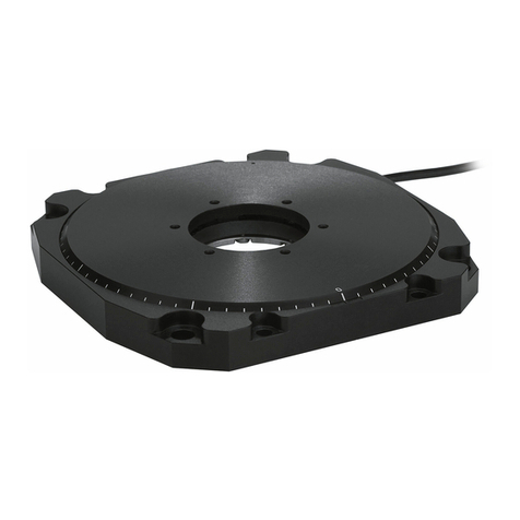
PI M-06 Series User manual

Physik Instrumente (PI) GmbH & Co. KG, Auf der Roemerstr. 1, 76228 Karlsruhe, Germany
MP47E
M
-06x Rotation Stage
User Manual
Version: 2.1
Date: 31.08.2020
This document describes the following
precision rotation stages (>360°):
M-06x.DG:
with closed-loop DC gear motor
M-06x.PD:
with DC motor and PWM control
x stands for the platform diameter:
0 =
60 mm
1 =
100 mm
2 = 120 mm

Physik Instrumente (PI) GmbH & Co. KG is the owner of the following trademarks:
PI®, PIC®, PICMA®, PILine®, PIFOC®, PIMag®, PiezoWalk®, NEXACT®,
NEXLINE®, NanoCube®, NanoAutomation®, Picoactuator®, PInano®
© 2020 Physik Instrumente (PI) GmbH & Co. KG, Karlsruhe, Germany. The text,
photographs and drawings in this manual are protected by copyright. With regard
thereto, Physik Instrumente (PI) GmbH & Co. KG retains all the rights. The use of any
text, images and drawings is permitted only in part and only when indicating the
source.
Original instructions
Document number: MP47E, MMa, Version 2.1
Subject to change without notice. This manual is superseded by any new release. The
latest release is available for download on our website.

1About this Document 3
1.1 Objective and Target Audience of this User Manual............................................3
1.2 Symbols and Typographic Conventions...............................................................3
1.3 Definition...............................................................................................................4
1.4 Figures..................................................................................................................4
1.5 Other Applicable Documents................................................................................5
2Safety 6
2.1 Intended Use ........................................................................................................6
2.2 General Safety Instructions..................................................................................6
2.3 Organizational Measures......................................................................................7
3Product Description 9
3.1 Model Overview....................................................................................................9
3.2 Product View.......................................................................................................11
3.3 Product Labeling.................................................................................................12
3.4 Direction of Motion..............................................................................................13
3.5 Scope of Delivery ...............................................................................................14
3.6 Technical Features.............................................................................................14
3.6.1 Encoder ............................................................................................14
3.6.2 Reference Point Switch ....................................................................14
3.6.3 Integrated PWM Amplifier.................................................................15
4Unpacking 17
5Installation 19
5.1 General Notes on Installation.............................................................................19
5.2 Optional: Modifying the Connection Orientation on the M-06x...........................20
5.3 Optional: Aligning the Hole Pattern of the Platform............................................22
5.4 Mounting the M-06x on a Surface ......................................................................24
5.5 Affixing the Load to the M-06x............................................................................26
5.6 Connecting the Motor Cable to the M-06x..........................................................27
5.7 Connecting the Power Supply to the M-06x.......................................................28
6Start-Up 29
6.1 General Notes on Start-Up.................................................................................29
6.2 Starting Up the Rotation Stage...........................................................................31
Contents
7Maintenance 32
7.1 General Notes on Maintenance..........................................................................32
7.2 Performing a Maintenance Run..........................................................................32
7.3 Cleaning the M-06x ............................................................................................33
8Troubleshooting 35
9Customer Service 37
10 Technical Data 39
10.1 Specifications......................................................................................................39
10.1.1 Data Table........................................................................................39
10.1.2 Maximum Ratings.............................................................................40
10.1.3 Ambient Conditions and Classifications ...........................................41
10.1.4 Reference Point Switch Specifications.............................................41
10.2 Dimensions.........................................................................................................42
10.3 Pin Assignment...................................................................................................44
10.3.1 Sub-D 15 (m) Controller Connection................................................44
10.3.2 Mini XLR3 (m) Power Supply Connection........................................45
11 Old Equipment Disposal 47
12 EC Declaration of Conformity 49

1 About this Document
M-06x Rotation Stage MP47E Version: 2.1 3
In this Chapter
Objective and Target Audience of this User Manual..................................................... 3
Symbols and Typographic Conventions........................................................................ 3
Definition........................................................................................................................ 4
Figures........................................................................................................................... 4
Other Applicable Documents......................................................................................... 6
Downloading Manuals................................................................................................... 6
1.1 Objective and Target Audience of this User Manual
This user manual contains the information needed for the intended use of the M-06x.
The stages of the M-060, M-061 and M-062 series are summarized under the
designation M-06x in this manual. (x stands for the platform diameter here. Details can
be found in the model overview (p. 9)).
Basic knowledge of servo systems, motion control concepts and applicable safety
measures is assumed.
The latest versions of the user manuals are available for download (p. 6) on our
website.
1.2 Symbols and Typographic Conventions
The following symbols and typographic conventions are used in this user manual:
NOTICE
Dangerous situation
If not avoided, the dangerous situation will result in damage to the equipment.
Actions to take to avoid the situation.
INFORMATION
Information for easier handling, tricks, tips, etc.
1
About this Document

1 About this Document
4 Version: 2.1 MP47E M-06x Rotation Stage
Symbol/Label Meaning
1.
2. Action consisting of several steps whose sequential order
must be observed
Action consisting of one or several steps whose sequential
order is irrelevant
List item
p. 5 Cross-reference to page 5
RS-232 Labeling of an operating element on the product (example:
socket of the RS-232 interface)
Warning sign on the product which refers to detailed
information in this manual.
1.3 Definition
Term Explanation
Load capacity Maximum load capacity in the vertical direction when the
rotation stage is mounted horizontally. The contact point of the
load is in the center of the platform.
Incremental position
sensor Sensor (encoder) for capturing changes of position or changes
of angle. Signals from the incremental position sensor are
used for axis position feedback. After switching on the
controller a reference point definition must be performed
before absolute target positions can be commanded and
reached.
1.4 Figures
For better understandability, the colors, proportions and degree of detail in illustrations
can deviate from the actual circumstances. Photographic illustrations may also differ
and must not be seen as guaranteed properties.

1 About this Document
M-06x Rotation Stage MP47E Version: 2.1 5
1.5 Other Applicable Documents
The devices and software tools which are mentioned in this documentation are
described in their own manuals.
Product Document
Stages with electric motors MP119EK Short Instructions
Matching controller User manual for the applied controller

2 Safety
6 Version: 2.1 MP47E M-06x Rotation Stage
In this Chapter
Intended Use ................................................................................................................. 6
General Safety Instructions........................................................................................... 6
Organizational Measures............................................................................................... 7
2.1 Intended Use
The M-06x is a laboratory device as defined by DIN EN 61010. It is intended for indoor
use and use in an environment that is free of dirt, oil and lubricants.
In accordance with its design and realization, the M-06x is intended for single-axis
positioning, adjusting and shifting of loads at different velocities. The M-06x is not
intended for applications in areas in which a failure would present severe risks to
human beings or the environment.
The M-06x is intended for horizontal or vertical mounting. For the load limits with
vertical mounting, see "General Notes on Installation" (p. 19).
The intended use of the M-06x is only possible when completely mounted and
connected.
The M-06x must be operated with a suitable controller (p. 14). The controller is not
included in the scope of delivery of the M-06x.
2.2 General Safety Instructions
The M-06x is built according to state-of-the-art technology and recognized safety
standards. Improper use can result in personal injury and/or damage to the M-06x.
Only use the M-06x for its intended purpose, and only use it if it is in a good
working order.
Read the user manual.
Immediately eliminate any faults and malfunctions that are likely to affect
safety.
The operator is responsible for the correct installation and operation of the M-06x.
2
Safety

2 Safety
M-06x Rotation Stage MP47E Version: 2.1 7
2.3 Organizational Measures
User manual
Always keep this user manual available with the M-06x.
The latest versions of the user manuals are available for download (p. 6) on
our website.
Add all information given by the manufacturer to the user manual, for example
supplements or technical notes.
If you give the M-06x to other users, also include this user manual as well as
other relevant information provided by the manufacturer.
Only use the device on the basis of the complete user manual. Missing
information due to an incomplete user manual can result in damage to
equipment.
Only install and operate the M-06x after you have read and understood this
user manual.
Personnel Qualification
The M-06x may only be installed, started up, operated, maintained and cleaned by
authorized and appropriately qualified personnel.


3 Product Description
M-06x Rotation Stage MP47E Version: 2.1 9
In this Chapter
Model Overview............................................................................................................. 9
Product View ............................................................................................................... 11
Product Labeling.......................................................................................................... 12
Direction of Motion....................................................................................................... 13
Scope of Delivery ........................................................................................................ 14
Accessories ................................................................................................................. 14
Suitable Controllers ..................................................................................................... 14
Technical Features...................................................................................................... 14
3.1 Model Overview
Classification of the stages
The stages of the M-060, M-061 and M-062 series are summarized in this manual
under the designation M-06x.
All models are precision rotation stages with backlash-compensated worm drives and
a continuous travel range in both directions of rotation. They differ with respect to:
Platform diameter
Drive type
Model Platform diameter [mm]
60 100 120
M-060.xx +
M-061.xx +
M-062.xx +
Model Drive type: DC motor with
Direct drive, PWM Gearhead, analog
M-06x.PD +
M-06x.DG +
3
Product Description

3 Product Description
10 Version: 2.1 MP47E M-06x Rotation Stage
Detailed model overview
Order
number Product name
M-060.DG Precision Rotation Stage, Ø 60 mm, 360°, closed-loop DC Gear Motor
M-060.PD Precision Rotation Stage, Ø 60 mm, 360°, ActiveDrive DC Motor
M-061.DG Precision Rotation Stage, Ø 100 mm, 360°, closed-loop DC Gear Motor
M-061.PD Precision Rotation Stage, Ø 100 mm, 360°, ActiveDrive DC Motor
M-062.DG Precision Rotation Stage, Ø 120 mm, 360°, closed-loop DC Gear Motor
M-062.PD Precision Rotation Stage, Ø 120 mm, 360°, ActiveDrive DC Motor
For further technical data, see the specifications (p. 39).

3 Product Description
M-06x Rotation Stage MP47E Version: 2.1 11
3.2 Product View
Figure 1: Components of the M-06x.PD models
Figure 2: Components of the M-06x.DG models
1 Motor
2 Motor flange
3 Platform
4 Scale ring
5 Base body
6 Controller connection (Sub-D 15 panel plug)
7 Power supply connection (Mini XLR3 panel plug)

3 Product Description
12 Version: 2.1 MP47E M-06x Rotation Stage
3.3 Product Labeling
Figure 3: Position of the product labeling
Position Labeling Description
1 Manufacturer's logo
1 CE conformity mark
1 Warning sign "Observe manual!"
1 M-060.PD Product name (example), the places after
the point refer to the model
1 113050975 Serial number (example), individual for
each M-06x
Meaning of the places (counting from left):
1 = internal information, 2 and 3 =
manufacturing year, 4 to 9 = consecutive
numbers
1 WWW.PI.WS Manufacturer's address (website)

3 Product Description
M-06x Rotation Stage MP47E Version: 2.1 13
Position Labeling Description
1 Old equipment disposal (p. 47)
1 Country of origin: Germany Country of origin
2 0 0° mark in the base body
3
0
180
Graduation on the scale ring of the moving
platform (detail)
Short line: 2°
Medium line: 10°
Long line: 90° and 270°
Numbers: 0° and 180°
4 24 VDC Power supply connection (only for
M-06x.PD models)
5 Controller Controller connection
3.4 Direction of Motion
Figure 4: Direction of motion
+ Direction of motion on positive command
0 0° mark in the base body: After a reference move, the 0° mark on the scale ring of the moving
platform is above the 0° mark in the base body.

3 Product Description
14 Version: 2.1 MP47E M-06x Rotation Stage
3.5 Scope of Delivery
Item
number Component
M-06x.xx Rotation stage according to the order (p. 9)
MP119EK Short instructions for stages with electric motors
Only M-060.xx models:
2493 Screw set for mounting the rotation stage:
6 M4x12 socket head cap screws ISO 4762
Allen wrench AF 3 DIN 911
Only M-061.xx / M-062.xx models:
2498 Screw set for mounting the rotation stage:
6 M4x16 socket head cap screws ISO 4762
Allen wrench AF 3 DIN 911
Only M-06x.PD models:
C-663.PS Wide-range-input power supply 24 V / 42 W
3763 Power cord
K050B0002 Adapter from 5.5 mm x 2.1 mm barrel connector to Mini
XLR3 (f) for the power supply connection
3.6 Technical Features
3.6.1 Encoder
The models are equipped with an incremental rotary encoder. For the encoder
resolution, refer to the table in the "Specifications" section (p. 39).
A rotary encoder is implemented at a rotating point in the drivetrain, e.g. the motor
shaft.
3.6.2 Reference Point Switch
The models are equipped with a direction-sensing reference point switch (see
"Reference Point Switch Specifications" (p. 41)).
The commands that use the reference signal are described in the user manual of the
controller and/or in the corresponding software manuals.

3 Product Description
M-06x Rotation Stage MP47E Version: 2.1 15
After a reference move of the M-06x, the 0° mark on the scale ring of the moving
platform is above the 0° mark in the base body.
3.6.3 Integrated PWM Amplifier
The M-06x.PD models with direct drive are equipped with a PWM amplifier
("ActiveDrive concept"). The PWM amplifier only receives the control signals from the
controller, whereas the supply voltage is provided via an external power supply. The
ActiveDrive concept allows high motor power and dynamics at low power loss.


4 Unpacking
M-06x Rotation Stage MP47E Version: 2.1 17
1. Unpack the M-06x with care.
2. Compare the contents against the items covered by the contract and against
the packing list.
3. Inspect the contents for signs of damage. If parts are missing or you notice
signs of damage, contact PI immediately.
4. Keep all packaging materials in case the product needs to be returned.
4
Unpacking

This manual suits for next models
6
Table of contents
Other PI Laboratory Equipment manuals

PI
PI L-505.02A212F User manual

PI
PI P-725 CDE2 Series User manual

PI
PI N-331 User manual

PI
PI L-505.011200 User manual

PI
PI H-820 User manual

PI
PI L-412.039232B User manual

PI
PI Pimag V-417.216211E1 User manual

PI
PI H-840 Series User manual

PI
PI Q-Motion Q-545 Series User manual

PI
PI L-412.XX9232B Series User manual
Popular Laboratory Equipment manuals by other brands

Sonation
Sonation USBB-S user manual

Sakura
Sakura Cyto-Tek 2500 Quick reference guide

Fisher Scientific
Fisher Scientific 88861023 Operation manual

Metrohm
Metrohm 942 Extension Module Vario SeS/PP manual

MikroTik
MikroTik GPEN11 quick start guide

NEW BRUNSWICK SCIENTIFIC
NEW BRUNSWICK SCIENTIFIC BioFlo 4500 Guide to operations