PI L-505.02A212F User manual

L505M0020EN ‒ 10/22/2018
User Manual
L-505.02A212F LINEAR STAGE WITH STEPPER MOTOR
MOTION | POSITIONING

Contents
1 Legal Information.........................................................................................................4
2 About this Document..................................................................................................5
2.1 Objective and Target Group..............................................................................5
2.2 Other Applicable Documents............................................................................5
2.3 Explanation of Symbols....................................................................................5
2.3.1 Typographic Conventions................................................................. 5
2.3.2 Symbols Used.................................................................................... 6
2.4 Figures................................................................................................................6
2.5 Downloading Manuals...................................................................................... 6
3 Safety............................................................................................................................8
3.1 Intended Use......................................................................................................8
3.2 General Safety Instructions.............................................................................. 8
3.3 Organizational Measures.................................................................................. 8
3.3.1 User Manual....................................................................................... 8
3.3.2 General Personnel Qualification.......................................................8
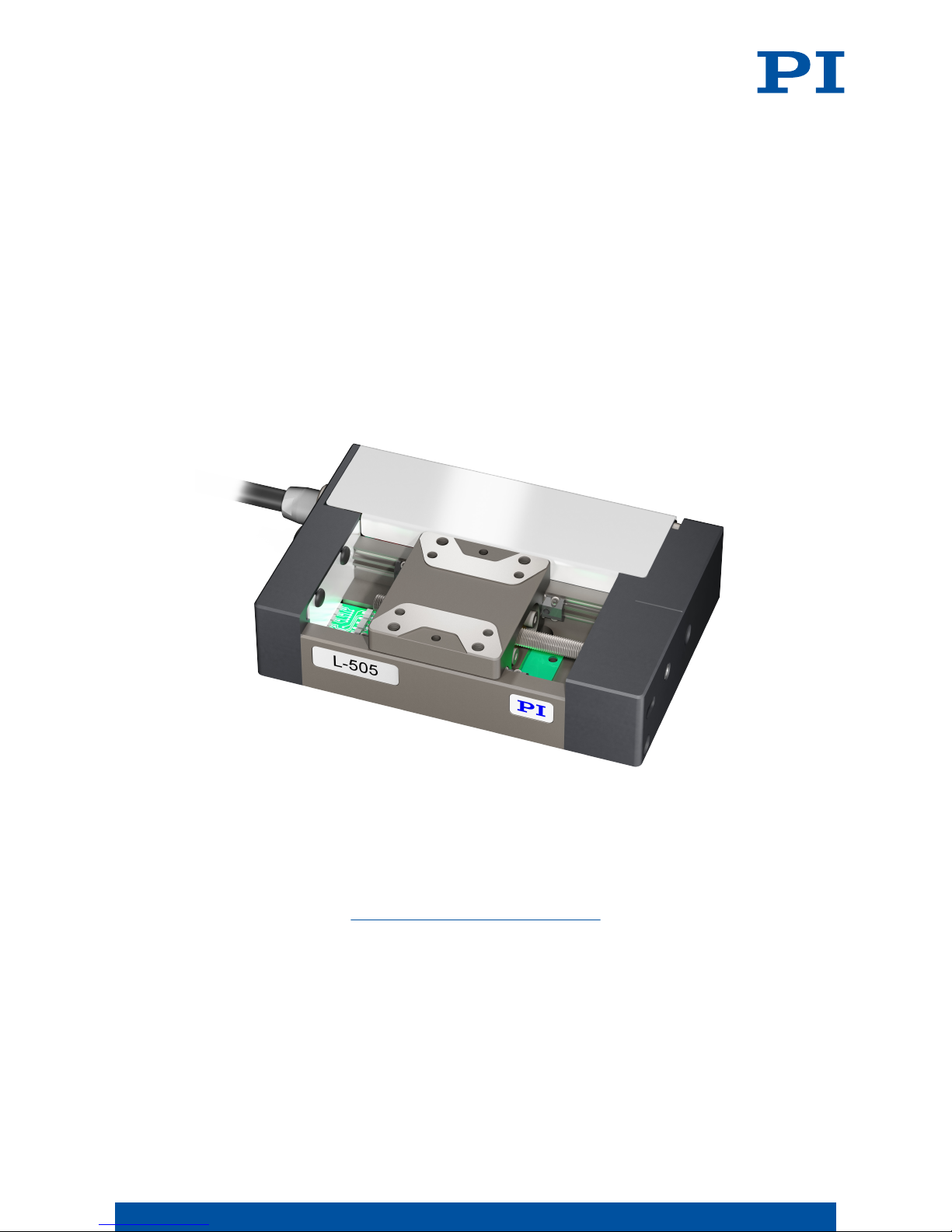
4 Product Description..................................................................................................... 9
4.1 Product Labeling................................................................................................9
4.1.1 Type Plate........................................................................................... 9
4.2 Scope of Delivery.............................................................................................10
4.3 Overview.......................................................................................................... 10
4.3.1 Base Body......................................................................................... 10
4.3.2 Drive Connection..............................................................................11
4.4 Suitable Electronics......................................................................................... 11
4.5 Accessories.......................................................................................................11
5 Unpacking.................................................................................................................. 12
6 Installation................................................................................................................. 13
6.1 Mounting the L-505.02A212F.......................................................................... 13
6.2 Connecting the L-505.02A212F to the Protective Earth Conductor.............. 14
6.3 Setting Up a Multi-Axis System..................................................................... 15
6.4 Building a Vertical Multi-Axis System............................................................17
6.5 Mounting the Load onto the L-505.02A212F..................................................20
6.6 Connecting the L-505.02A212F........................................................................21
7 Startup / Operation................................................................................................... 23
7.1 Starting and operating the L-505.02A212F.....................................................23
8 Maintenance...............................................................................................................25
8.1 Maintenance Run.............................................................................................25
8.2 Relubricating.................................................................................................... 25
8.3 Moving the Motion Platform by Hand........................................................... 26
8.4 Cleaning............................................................................................................26
CONTENTS L505M0020EN ‒ 10/22/2018
2MOTION | POSITIONING

9 Troubleshooting......................................................................................................... 28
10 Transportation............................................................................................................29
11 Customer Service Department.................................................................................30
12 Technical Data............................................................................................................ 31
12.1 Specifications...................................................................................................31
12.2 Maximum Ratings........................................................................................... 33
12.3 Ambient Conditions and Classifications........................................................33
12.4 Dimensions...................................................................................................... 34
13 Old Equipment Disposal........................................................................................... 36
14 Appendix.................................................................................................................... 38
14.1 Pin Assignment................................................................................................38
14.1.1 Motor and position sensor connector............................................38
14.2 Drive properties............................................................................................... 39
14.3 Reference point switch specifications............................................................39
14.4 Limit switch specifications..............................................................................39
15 EU Declaration of Conformity...................................................................................41
CONTENTS L505M0020EN ‒ 10/22/2018
3MOTION | POSITIONING

1 Legal Information
The following company names and brands are registered trademarks of Physik Instrumente
(PI) GmbH & Co. KG:
PI®, PIC®, NanoCube®, PICMA®, PIFOC, PILine®, NEXLINE®, PiezoWalk®, PicoCube®,
PiezoMove®, PIMikroMove, NEXACT®, Picoactuator®, PInano®, NEXSHIFT®, PITOUCH®,
PIMag®, PIHera, Q-Motion®
The patents held by PI can be found in our list at http://www.physikinstrumente.com/en/
about-pi/patents.
© 2018 Physik Instrumente (PI) GmbH & Co. KG, Karlsruhe, Germany. The text, photographs,
and drawings in this manual are protected by copyright. With regard thereto, Physik
Instrumente (PI) GmbH & Co. KG reserves all rights. The use of any text, images and
drawings is permitted only in part and only when indicating the source.
Original instructions
First print: 10/22/2018
Document number: L505M0020en, LTr
Subject to change. This manual is superseded by any new release. The latest versions of the
user manuals are available for download (p. 6) at www.pi.ws.
Publisher:
PI miCos GmbH
Freiburger Strasse 30
79427 Eschbach
Germany
www.pi.de
Customer service department:
Physik Instrumente (PI) GmbH & Co. KG
Auf der Roemerstrasse 1
76228 Karlsruhe
Germany
www.pi.de
1 LEGAL INFORMATION L505M0020EN ‒ 10/22/2018
4MOTION | POSITIONING

2 About this Document
2.1 Objective and Target Group
This user manual contains the information needed for the intended use of the L-505.02A212F.
Basic knowledge of closed-loop systems, motion control concepts, and applicable safety
measures is assumed.
2.2 Other Applicable Documents
The devices and software tools that are mentioned in this documentation are described in
separate manuals.
Document number Document type Product
MP146EK Short instructions Positioners with electric motors
SM148E Software Manual PIMikroMove
MS208E User Manual C-663 Mercury Step Controller
MS241E User Manual C-663.12 Mercury Step Stepper Motor Con-
troller
- Hardware Manual SMC Hydra Motion Controller
- Hardware Manual SMC Pollux Motion Controller
The latest versions of the user manuals can be downloaded (p. 6) at www.pi.ws.
2.3 Explanation of Symbols
This chapter explains the symbols and markings used by PI in this user manual.
2.3.1 Typographic Conventions
Symbol / Label Meaning
1.
2.
Action consisting of several steps whose sequential order must be ob-
served
■ Lists
p. 5 Cross-reference to page 5
RS-232 Labeling of an operating element on the product (example: socket of
the RS-232 interface)
Start > Settings
Menu path in the PC software (example: to open the menu, the
Start
and
Settings
menus must be clicked successively)
POS? Command line or a command from PI's General Command Set (GCS)
(example: command to get the axis position)
Device S/N
Parameter name (example: parameter where the serial number is stor-
ed)
5Value that must be entered or selected via the PC software
2 ABOUT THIS DOCUMENT L505M0020EN ‒ 10/22/2018
5MOTION | POSITIONING

2.3.2 Symbols Used
Symbol / Label Meaning
General hazard symbol
DANGER
Dangerous situation
Failure to observe can lead to death or serious injury.
►Measures for avoiding the risk.
WARNING
Dangerous situation
Failure to observe can lead to serious injury.
►Action to take to avoid the risk.
CAUTION
Dangerous situation
Failure to observe can lead to minor injury.
►Actions to take to avoid the risk.
NOTICE
Dangerous situation
Failure to observe can lead to material damage.
►Action to take to avoid the risk.
Information
Additional information on the L-505.02A212F that can affect your application.
2.4 Figures
For better understandability, the colors, proportions and degree of detail in illustrations can
deviate from the actual circumstances. Photographic illustrations may also differ and must
not be seen as guaranteed properties.
2.5 Downloading Manuals
The latest versions of the user manuals can be downloaded (p. 6) at www.pi.ws.
For products that are supplied with software (CD in the scope of delivery), access to the
manuals is protected by a password. Protected content is only displayed on the website after
entering the login data. You need the product CD to get the login data.
If a manual is missing or problems occur with downloading, contact our customer service
department (p. 30).
Downloading Manuals
1. Open the website www.pi.ws.
2. If the product was shipped with a CD: Log into the website:
a) Click Login.
b) Enter the login data.
2 ABOUT THIS DOCUMENT L505M0020EN ‒ 10/22/2018
6MOTION | POSITIONING

The login data is in the [...]_Releasenews_[...].pdf in the Manuals directory on the
product CD.
If necessary: Follow the link and register yourself to get the login data.
c) Click Login or press the Enter key.
3. Search for the product:
a) Click Search.
b) Enter the product number up to the period (e.g., L-505) into the search field.
c) Click Start search or press the Enter key.
d) If necessary: Click Load more results at the bottom of the list.
4. Click the corresponding product in the list of search results.
5. Click the Downloads tab.
➔The manuals are shown under
Documentation
.
6. Click the desired manual and save it.
2 ABOUT THIS DOCUMENT L505M0020EN ‒ 10/22/2018
7MOTION | POSITIONING

3 Safety
3.1 Intended Use
The L-505.02A212F is a laboratory device as defined by DIN EN 61010-1. It is intended for
indoor use and use in an environment that is free of dirt, oil, and lubricants.
In accordance with its design, the L-505.02A212F is intended for positioning, adjusting and
shifting loads in one axis at various velocities. The L-505.02A212F is not intended for
applications in areas, in which a failure would present severe risks to human beings or the
environment.
The intended use of the L-505.02A212F is only possible when completely mounted and
connected. The L-505.02A212F must be operated with suitable electronics (p. 11). The
electronics are not in the scope of delivery of the L-505.02A212F.
The L-505.02A212F may not be used for purposes other than those stated in this user
manual. The L-505.02A212F may only be used in compliance with the technical specifications
and instructions in this user manual.
3.2 General Safety Instructions
The L-505.02A212F is built according to state-of-the-art technology and recognized safety
standards. Improper use of the L-505.02A212F may result in personal injury and/or damage
to the L-505.02A212F.
►Use the L-505.02A212F only for its intended purpose and if it is in perfect condition.
►Read the user manual.
►Eliminate any faults and malfunctions that are likely to affect safety immediately.
The operator is responsible for correct installation and operation of the L-505.02A212F.
3.3 Organizational Measures
3.3.1 User Manual
►Always keep this user manual available with the L-505.02A212F. The latest versions of the
user manuals can be downloaded (p. 6) at www.pi.ws.
►Add all information from the manufacturer such as supplements or technical notes to the
user manual.
►If you give the L-505.02A212F to a third party, also include this user manual as well as
other relevant information provided by the manufacturer.
►Only use the device on the basis of the complete user manual. Missing information due to
an incomplete user manual can result in minor injury and damage to equipment.
►Only install and operate the L-505.02A212F after you have read and understood this user
manual.
3.3.2 General Personnel Qualification
The L-505.02A212F may only be installed, started up, operated, maintained, and cleaned by
authorized and appropriately qualified personnel.
3 SAFETY L505M0020EN ‒ 10/22/2018
8MOTION | POSITIONING

4 Product Description
4.1 Product Labeling
1 2 3 4
Figure 1: Product label on the L-505.02A212F
1. Type plate
2. Warning symbol: Electrostatic sensitive device
3. Protective earth connector
4. Warning symbol: Risk of crushing
4.1.1 Type Plate
The type plate is on the plug connector of the L-505.02A212F.
Figure 2: Type plate of the L-505.02A212F
1. Product number (example)
2. Serial number (example), individual for each L-505.02A212F
Meaning of the position (counting from the left):
1 = internal information,
2 and 3 = year of manufacture,
4 to 9 = consecutive numbers
3. Warning and conformity symbols (Old equipment disposal (p. 36), CE mark (p. 41))
4 PRODUCT DESCRIPTION L505M0020EN ‒ 10/22/2018
9MOTION | POSITIONING

4.2 Scope of Delivery
Product number Description
L-505.02A212F Linear stage according to order
L505B1000 Mounting kit for mounting the L-505.02A212F,
consisting of
■4 socket head screws, ISO 4762 M3×6
■2 dowel pins, ISO 8734, 2m6 × 8
000036450 M4 screw set for protective earth, consisting
of:
■1 flat-head screw with cross recess,
ISO 7045 M4×8
■2 safety washers
■2 flat washers
720090669-0300 Drive/encoder cable, stepper motor and en-
coder to SMC Hydra controller, HD Sub-D 26
(f) to Sub-D 15 (m) (motor) and HD Sub-D 15
(encoder), 3 m
7200900860-0300 Drive/encoder cable, stepper motor and en-
coder to C-663.11 Mercury Step stepper mo-
tor controller, HD Sub-D 26 (f) to Sub-D 15
(m), 3 m
C-815.00UP0100-0300 Drive/encoder cable, stepper motor and en-
coder to C-663.12 Mercury Step stepper mo-
tor controller, HD Sub-D 26 (f) to HD-Sub-D
26 (m), 3 m
MP146EK Short instructions for positioners with elec-
tric motors
4.3 Overview
1. Legend
4.3.1 Base Body
The base body is the basis of the positioner. The L-505.02A212F is mounted onto a surface
via the base body (p. 13).
The base body comprises the following subassembly or subassemblies:
Drive screw
The drive screw converts the rotary motion of the drive to linear motion of the motion
platform.
Reference Point Switch
The reference point switch is a sensor whose fixed position serves as the reference point for
incremental sensor signals.
4 PRODUCT DESCRIPTION L505M0020EN ‒ 10/22/2018
10 MOTION | POSITIONING

Limit switches
The limit switches are sensors at each end of the travel range that enable the electronics to
abort motion in order to prevent the motion platform from colliding with the mechanical
hard stop.
Position sensor
The sensor measures the position of the motion platform incremental to a known reference
point. Optical linear encoders measure the actual position directly (direct position
measuring). Therefore, errors in the drive, such as nonlinearity, backlash or elastic
deformations cannot influence the measurement of the position.
4.3.2 Drive Connection
The electrical connection to the electronics is established via the drive connection (p. 21).
The drive connection transmits the supply voltage, the signals for the drive as well as the
sensor signals of the L-505.02A212F.
The drive connection comprises the following subassembly or subassemblies:
ID chip
Information on the L-505.02A212F (e.g., type, serial number, date of manufacture, version of
the hardware) is stored in parameters on the ID chip. Electronics that support the ID chip
evaluate the data from the ID chip and can select the corresponding type of positioner
automatically from the positioner database during startup.
For more information on ID chip recognition, see the manual for the electronics.
4.4 Suitable Electronics
The L-505.02A212F must be connected to suitable electronics that supply the necessary
voltage for operating and if required, to evaluate the sensor and limit switch signals. The
following electronics are suitable:
Product number Description
C-663.12 Mercury Step Stepper Motor Controller
SMC Hydra Motion Controller
SMC Pollux Motion Controller
To order, contact our customer service department (p. 30).
4.5 Accessories
Product number Description
L-505.AP1 Mounting adapter for vertical mounting of
L-505 positioners
To order, contact our customer service department (p. 30).
4 PRODUCT DESCRIPTION L505M0020EN ‒ 10/22/2018
11 MOTION | POSITIONING

5 Unpacking
Unpacking the L-505.02A212F
1. Unpack the L-505.02A212F with care.
2. When the L-505.02A212F was delivered with ESD protective caps on the connections: Do
not remove the ESD protective caps.
3. Compare the contents with the scope of delivery according to the contract and the
delivery note.
4. Inspect the contents for signs of damage. If any parts are damaged or missing, contact
our customer service department (p. 30) immediately.
5. Keep all packaging materials in case the product needs to be returned.
5 UNPACKING L505M0020EN ‒ 10/22/2018
12 MOTION | POSITIONING

6 Installation
6.1 Mounting the L-505.02A212F
Overview
Tools and Accessories
■Screw set for mounting the L-505.02A212F (p. 10)
■Suitable screwdriver
Requirements
✓You have read and understood the general safety instructions (p. 8).
✓You have provided a suitable surface with the holes necessary for the screws and if
required, locating pins (p. 34).
■The flatness of the surface is ≤ 10 μm.
■For applications with large temperature changes: The surface should have the same or
similar thermal expansion properties as the L-505.02A212F.
✓You have accounted for the space required to route cables without bending and
according to regulations.
CAUTION
Risk of crushing by moving parts!
Risk of minor injuries from crushing between the moving parts of the L-505.02A212F or the
load and a fixed part or obstacle.
►Use safeguards to protect limbs areas where they could be caught by moving parts.
►Observe the safety distances in accordance with DIN EN ISO 13857 when installing
protective structures.
6 INSTALLATION L505M0020EN ‒ 10/22/2018
13 MOTION | POSITIONING

NOTICE
Damage due to collisions!
Collisions can damage the L-505.02A212F, the load to be moved, and the surroundings.
►Make sure that collisions are not possible between the L-505.02A212F, the load to be
moved, and the surroundings in the motion range of the L-505.02A212F.
►Do not place any cables or other objects in areas where they could be caught by moving
parts.
NOTICE
Excessively long screws and locating pins
Screws and locating pins that are inserted too deeply can damage the L-505.02A212F.
►Pay attention to the depth of the mounting and locating holes (p. 35) in the
L-505.02A212F.
►Only use screws and locating pins of the correct length for the respective mounting holes.
Mounting the L-505.02A212F on a Surface
1. If necessary: Allow access to the mounting holes in the base body of the L-505.02A212F.
Possible measures:
■Temporary startup of the positioner (p. 23) and command the platform to a suitable
position
■Move the motion platform by hand
2. Align the L-505.02A212F on the surface so that the corresponding mounting holes in the
L-505.02A212F and the surface overlap.
3. Insert the screws into all accessible mounting holes and tighten.
4. If necessary: Repeat steps 1 to 3 for all concealed mounting holes.
5. Check that the L-505.02A212F is affixed firmly to the surface.
6.2 Connecting the L-505.02A212F to the Protective Earth Conductor
It is only necessary to connect the L-505.02A212F' to the protective earth conductor when
both of the following conditions are met:
■The load on the motion platform must be connected to the protective earth conductor, but
it is not possible to connect the protective earth conductor directly.
■The load and the motion platform are connected conductively to each other.
Overview
1. Connector for the protective earth conductor on the L-505.02A212F, indicated by the
protective earth symbol
2. Safety washer
3. Flat washer
6 INSTALLATION L505M0020EN ‒ 10/22/2018
14 MOTION | POSITIONING

4. Protective earth conductor lug
5. Screw, ISO 7045 M4×8
Tools and Accessories
■Suitable protective earth conductor:
■Cable cross section ≥ 0.75 mm2
■Contact resistance <0.1 Ω at 25 A at all connection points relevant for attaching the
protective earth conductor
■M4 screw set for protective earth, in the scope of delivery of the L-505.02A212F (p. 10)
■Suitable screwdriver
Requirements
✓You have read and understood the general safety instructions (p. 8).
Information
►Observe the applicable standards for connecting the protective earth conductor.
Connecting the L-505.02A212F to the Protective Earth Conductor
1. If necessary, attach a suitable cable lug to the protective earth conductor.
2. Attach the cable lug of the protective earth conductor to the protective earth connection
as shown in the illustration of the L-505.02A212F.
3. Tighten the screw with a torque of 1.2 Nm to 1.5 Nm.
4. Make sure that the contact resistance is <0.1 Ω at 25 A at all connection points relevant for
attaching the protective earth conductor.
6.3 Setting Up a Multi-Axis System
The L-505.02A212F can be used in XY systems.
Designations in these instructions:
■Lower positioner: Forms the basis of the multi-axis system, is attached to an underlying
surface
■Upper positioner: Forms the upper axis of the multi-axis system, is attached to the lower
positioner rotated by 90°
Tools and Accessories
■Screws in the scope of delivery of the L-505.02A212F:
■4 screws ISO 4762, M3×6, A2
■2 locating pins ISO 8734, 2m6×8
■Suitable screwdriver
Requirements
✓You have read and understood the general safety instructions (p. 8).
✓The positioners are not connected to the electronics.
✓The lower positioner has been mounted onto the underlying surface properly (p. 13).
✓You have accounted for the space required to route cables without bending and
according to regulations.
6 INSTALLATION L505M0020EN ‒ 10/22/2018
15 MOTION | POSITIONING

NOTICE
Impermissibly high load on the positioners!
In a multi-axis system, the stage used for the upper axis must also be moved. Impermissibly
high loads impair the motion and can damage the positioners.
►Pay attention to the maximum permissible forces (p. 31) that may act on the motion
platform.
►In the case of multi-axis systems, include the masses of the positioners to be moved
when calculating the load.
NOTICE
Excessively long screws and locating pins
Screws and locating pins that are inserted too deeply can damage the L-505.02A212F.
►Pay attention to the depth of the mounting and locating holes (p. 35) in the
L-505.02A212F.
►Only use screws and locating pins of the correct length for the respective mounting holes.
Building an XY Multi-Axis System
1. Mount the L-505.02A212F onto the lower L-505.
a) Insert two locating pins 2 mm m6 × 8 mm into the motion platform of the lower L-505.
2. Align the L-505.02A212F to the lower L-505.
3. Insert the M3×6 screws into the holes in the upper L-505 and tighten them.
6 INSTALLATION L505M0020EN ‒ 10/22/2018
16 MOTION | POSITIONING

6.4 Building a Vertical Multi-Axis System
The L-505.02A212F can be used as Z axis. A mounting bracket is necessary, see Optional
Accessories (p. 11).
Designations in these instructions:
■Horizontal positioner: Forms the horizontal axis of the multi-axis system
■Vertical positioner: Forms the vertical axis of the multi-axis system, is attached to the
mounting bracket rotated around 90°
6 INSTALLATION L505M0020EN ‒ 10/22/2018
17 MOTION | POSITIONING

Z Mounting Overview
The mounting bracket for the L-505 can be attached in two different configurations.
Requirements
✓You have read and understood the general safety instructions (p. 8).
✓The positioners are not connected to the electronics.
✓The lower positioner has been mounted onto the underlying surface properly (p. 13).
✓You have accounted for the space required to route cables without bending and
according to regulations.
NOTICE
Impermissibly high load on the positioners!
In a multi-axis system, the stage used for the upper axis must also be moved. Impermissibly
high loads impair the motion and can damage the positioners.
►Pay attention to the maximum permissible forces (p. 31) that may act on the motion
platform.
►In the case of multi-axis systems, include the masses of the positioners to be moved
when calculating the load.
NOTICE
Unwanted changes in position with vertical mounting!
If the load exceeds the self-locking of the L-505.02A212F when the stage is mounted
vertically, unwanted changes in the position of the motion platform will occur. Unwanted
changes in the position of the motion platform can damage the drive, the load or the
environment.
►If the L-505.02A212F is mounted vertically, make sure that the installed load is lower than
the self-locking of the drive. (see Specifications (p. 31))
NOTICE
Excessively long screws and locating pins
Screws and locating pins that are inserted too deeply can damage the L-505.02A212F.
►Pay attention to the depth of the mounting and locating holes (p. 35) in the
L-505.02A212F.
►Only use screws and locating pins of the correct length for the respective mounting holes.
6 INSTALLATION L505M0020EN ‒ 10/22/2018
18 MOTION | POSITIONING

Tools and Accessories
■Mounting bracket, see Optional Accessories (p. 11)
■mounting hardware, in the scope of delivery of the L-505
■4 screws ISO 4762, M3×6, A2
■2 locating pins ISO 8734, 2m6×8
■Mounting hardware, scope of delivery of the mounting bracket
■4 screws ISO 4762, M3×10, A2
■2 locating pins ISO 8734, 2m6×8
Building a Vertical Multi-Axis System
1. Attach the mounting bracket to the lower L-505.
a) Insert two locating pins 2 mm m6 × 8 mm into the motion platform of the lower L-505.
b) Align the mounting bracket to the lower L-505.
c) Insert the M3×10 screws into the holes in the mounting bracket and tighten them.
2. Attach the upper L-505 to the mounting bracket.
a) Insert two 2 mm m6 × 8 mm locating pins into the mounting bracket.
b) Align the L-505 to the mounting bracket.
c) Insert the M3×6 screws into the holes in the upper L-505 and tighten them.
6 INSTALLATION L505M0020EN ‒ 10/22/2018
19 MOTION | POSITIONING

6.5 Mounting the Load onto the L-505.02A212F
Overview
Figure 3: Load mounting at the hole in the pusher of the L-505.02A212F
1. Screws
2. Load
3. Motion platform of the L-505.02A212F
Tools and Accessories
■At least 3 screws with suitable dimensions (p. 34)
■Suitable tools for tightening the screws
■Optional: 2 suitably dimensioned dowel pins as locating pins for aligning the load on the
L-505.02A212F
Requirements
✓You have read and understood the general safety instructions (p. 8).
✓You have mounted the L-505.02A212F on the surface (p. 13) properly.
✓The L-505.02A212F is not connected to the electronics.
6 INSTALLATION L505M0020EN ‒ 10/22/2018
20 MOTION | POSITIONING
Table of contents
Other PI Laboratory Equipment manuals