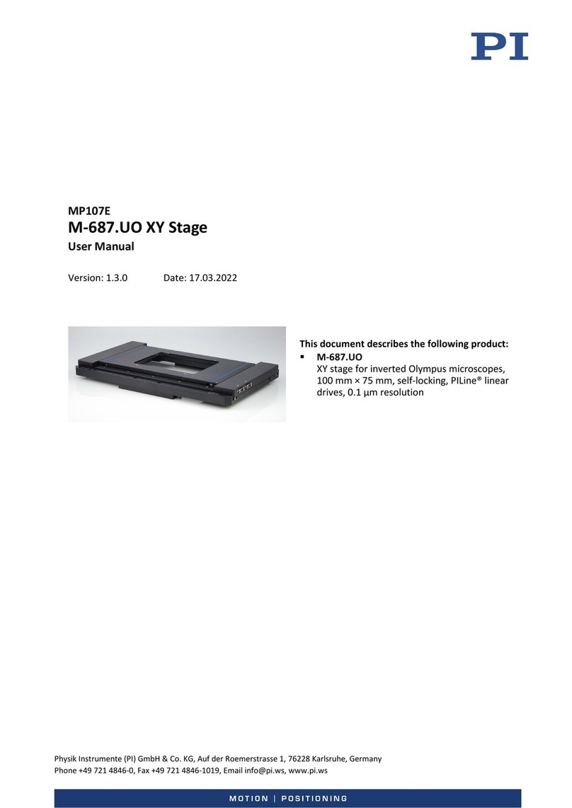
PI P-545 User manual

Physik Instrumente (PI) GmbH & Co. KG, Auf der Roemerstrasse 1, 76228 Karlsruhe, Germany
Phone +49 721 4846-0, Fax +49 721 4846-1019, Email info@pi.ws, www.pi.ws
PZ272E
P
-545 Nanopositioners
User Manual
Version: 1.1.0
Date: 10.01.2022
This document describes the following products:
P-545.2C8S PInano® Cap XY Piezo System
PInano® XY piezo system, clear aperture for
microscope slides, 200 µm × 200 µm, capacitive
sensors, with USB digital controller*
P-545.3C8S PInano® Cap XYZ Piezo System
PInano® XYZ piezo system, clear aperture for
microscope slides, 200 µm × 200 µm × 200 µm,
capacitive sensors, with USB digital controller*
P-545.2R8S PInano® XY Piezo System
PInano® XY piezo system, clear aperture for
microscope slides, 200 µm × 200 µm,
piezoresistive sensors, with USB digital
controller*
P-545.3R8S PInano® XYZ Piezo System
PInano® XYZ piezo system, clear aperture for
microscope slides, 200 µm × 200 µm × 200 µm,
piezoresistive sensors, with USB digital
controller*
P-545.3D8S PInano® Trak XYZ Piezo Tracking
System
High dynamics PInano® XYZ piezo system, clear
aperture for microscope slides, 70 µm × 70 µm
× 50 µm, direct drive, piezoresistive sensors,
with USB digital controller*
*The controller for the system is described in a
separate manual.

The following company names and brands are registered trademarks of Physik Instrumente (PI) GmbH & Co.
KG:
PI®, NanoCube®, PICMA®, PILine®, NEXLINE®, PiezoWalk®, NEXACT®, Picoactuator®, PInano®, PIMag®,
Q-Motion®
The patents held by PI are found in our patent list: https://www.physikinstrumente.com/en/about-pi/patents
© 2022 Physik Instrumente (PI) GmbH & Co. KG, Karlsruhe, Germany. The text, photographs and drawings in
this manual are protected by copyright. With regard thereto, Physik Instrumente (PI) GmbH & Co. KG retains
all the rights. The use of any text, images and drawings is permitted only in part and only when indicating the
source.
Original instructions
First printing: 10.01.2022
Document number: PZ272E, CBo, Version 1.1.0
Subject to change without notice. This manual is superseded by any new release. The latest release is
available for download (p. 3) on our website.

1About this Document 1
1.1 Objective and Target Group of this User Manual ...................................................... 1
1.2 Symbols and Typographic Conventions...................................................................... 1
1.3 Figures ........................................................................................................................ 2
1.4 Other Applicable Documents ..................................................................................... 2
1.5 Downloading Manuals................................................................................................ 3
2Safety 5
2.1 Intended Use .............................................................................................................. 5
2.2 General Safety Instructions ........................................................................................ 5
2.3 Organizational Measures............................................................................................ 7
3Product Description 9
3.1 Model Overview ......................................................................................................... 9
3.2 Product View ............................................................................................................ 10
3.3 Product Labeling....................................................................................................... 10
3.4 Scope of Delivery...................................................................................................... 12
3.5 Accessories ............................................................................................................... 12
3.6 Technical Features.................................................................................................... 13
3.6.1 PICMA® Piezo Actuators .............................................................................. 13
3.6.2 Flexure Guides ............................................................................................. 13
3.6.3 Position Sensors........................................................................................... 13
3.7 Integration of the P-545 into Microscopes .............................................................. 14
4Unpacking 15
5Installation 17
5.1 General Notes on Installing ...................................................................................... 17
5.2 Connecting the P-545 to the Protective Earth Conductor ....................................... 18
5.3 Mounting the P-545 ................................................................................................. 20
5.3.1 Mounting the P-545 onto a Surface ............................................................ 20
5.3.2 Mounting the P-545 onto an M-545 XY Stage............................................. 22
5.4 Fixing the Load.......................................................................................................... 23
5.4.1 Fixing a Load to the Motion Platform.......................................................... 25
5.4.2 Mounting Holders for Petri Dishes, Microscope Slides and
Accessories .................................................................................................. 26
Contents
6Starting and Operating 27
6.1 General Notes on Starting........................................................................................ 27
6.2 Operating the P-545 ................................................................................................. 28
6.3 Discharging the P-545............................................................................................... 29
7Maintenance 31
7.1 General Notes on Maintenance ............................................................................... 31
7.2 Cleaning the P-545 ................................................................................................... 31
8Troubleshooting 33
9Customer Service 35
10 Technical Data 37
10.1 Specifications............................................................................................................ 37
10.1.1 Data Table.................................................................................................... 37
10.1.2 Maximum Ratings........................................................................................ 40
10.1.3 Ambient Conditions and Classifications ...................................................... 41
10.2 Dimensions ............................................................................................................... 42
10.2.1 P-545 Positioner .......................................................................................... 42
10.2.2 P-545.SH4 Microscope Slide and Petri Dish Holder..................................... 43
10.2.3 P-545.SH3 Microscope Slide Holder ............................................................ 44
10.2.4 P-545.PD3 Petri Dish Holder........................................................................ 45
10.2.5 P-545.PP3 Universal Holding Plate .............................................................. 45
10.3 Torque for Stainless Steel Screws (A2-70)................................................................ 46
10.4 Pin Assignment ......................................................................................................... 46
11 Old Equipment Disposal 51
12 European Declarations of Conformity 53

1 About this Document
P-545 Nanopositioners PZ272E Version: 1.1.0 1
In this Chapter
Objective and Target Group of this User Manual.......................................................................... 1
Symbols and Typographic Conventions ......................................................................................... 1
Figures............................................................................................................................................ 2
Other Applicable Documents......................................................................................................... 2
Downloading Manuals ................................................................................................................... 3
1.1 Objective and Target Group of this User Manual
This user manual contains the information required for using the P-545.xx8H positioner
belonging to the P-545.xx8S system as intended (x stands for the respective model). Unless
stated otherwise, "P-545" only refers to the positioner in this manual. The controller in the
system is described in a separate manual (p. 2).
Basic knowledge of control technology, drive technologies, and suitable safety measures is
assumed.
The latest versions of the user manuals are available for download (p. 3) on our website.
1.2 Symbols and Typographic Conventions
The following symbols and typographic conventions are used in this user manual:
CAUTION
Dangerous situation
Failure to comply could lead to minor injury.
Precautionary measures for avoiding the risk.
NOTICE
Dangerous situation
Failure to comply could cause damage to equipment.
Precautionary measures for avoiding the risk.
INFORMATION
Information for easier handling, tricks, tips, etc.
1
About this Document

1 About this Document
2 Version: 1.1.0 PZ272E P-545 Nanopositioners
Symbol/Label Meaning
1.
2.
Action consisting of several steps with strict sequential order
Action consisting of one or more steps without relevant sequential
order.
Bullet
p. 5
Cross-reference to page 5
RS-232
Label on the product indicating an operating element (example:
RS-232 interface socket)
Warning signs attached to the product that refer to detailed
information in this manual.
1.3 Figures
For better understandability, the colors, proportions, and degree of detail in illustrations can
deviate from the actual circumstances. Photographic illustrations may also differ and must not
be seen as guaranteed properties.
1.4 Other Applicable Documents
The devices and software tools from PI mentioned in this documentation are described in
separate manuals.
The latest versions of the user manuals are available for download (p. 3) on our website.
Product Document
E-727 digital multichannel piezo controller,
part of the P-545 system
E727T0005 technical note
PIMikroMove
SM148E software manual
P-5xx / P-6xx / P-7xx piezo positioners
PZ240EK short instructions

1 About this Document
P-545 Nanopositioners PZ272E Version: 1.1.0 3
1.5 Downloading Manuals
INFORMATION
If a manual is missing or problems occur with downloading:
Contact our customer service department (p. 35).
Downloading Manuals
1. Open the website www.pi.ws.
2. Search the website for the product number (e.g., P-545) or the product family (e.g.,
PInano®).
3. Click the corresponding product to open the product detail page.
4. Click the Downloads tab.
The manuals are shown under Documentation. Software manuals are shown under
General Software Documentation.
5. Click the desired manual and fill out the inquiry form.
The download link will then be sent to the email address entered.


2 Safety
P-545 Nanopositioners PZ272E Version: 1.1.0 5
In this Chapter
Intended Use.................................................................................................................................. 5
General Safety Instructions............................................................................................................ 5
Organizational Measures ............................................................................................................... 7
2.1 Intended Use
The P-545 positioner is a laboratory device as defined by DIN EN 61010-1. It is intended for
indoor use and use in an environment that is free of dirt, oil, and lubricants.
According to its design, the P-545 is intended for fine positioning as well as moving small
objects quickly and precisely. The specifications for the P-545 apply to horizontal mounting.
Depending on the version, moving is done as follows:
System Motion Axis
.2C8S / .2R8S
In two axes horizontally
X, Y
.3C8S / .3R8S / .3D8S
In two axes horizontally and in one axis vertically
X, Y, Z
The P-545 positioner can only be used as intended in conjunction with the controller belonging
to the system.
2.2 General Safety Instructions
The P-545 is built according to state-of-the-art technology and recognized safety standards.
Improper use can result in personal injury and/or damage to the P-545.
Use the P-545 for its intended purpose only, and only when it is in perfect technical
condition.
Read the user manual.
Eliminate any malfunctions that may affect safety immediately.
The operator is responsible for the correct installation and operation of the P-545.
2
Safety

2 Safety
6 Version: 1.1.0 PZ272E P-545 Nanopositioners
The P-545 is driven by piezo actuators. Temperature changes and compressive stress can induce
charges in piezo actuators. Piezo actuators can remain charged for several hours after
disconnecting the electronics. Touching or short-circuiting the contacts in the P-545's connector
can lead to minor injuries from electric shock. The piezo actuators can be destroyed by an
abrupt contraction.
Do not open the P-545.
Discharge the positioner's piezo actuators before installing:
Connect the positioner to the switched-off PI controller equipped with an internal
discharge resistor.
Do not pull the connector out of the controller during operation.
Do not touch the contacts in the connector.
Use screws to secure the positioner's connectors against being pulled out of the
controller.
If a protective earth conductor is not or not properly connected, dangerous touch voltages can
occur on the P-545 in the case of malfunction or failure of the system. If there are touch
voltages, touching the P-545 can result in minor injuries from electric shock.
Connect the P-545 to a protective earth conductor (p. 18) before starting.
Do not remove the protective earth conductor during operation.
If the protective earth conductor has to be removed temporarily (e.g., in the case of
modifications), reconnect the P-545 to the protective earth conductor before restarting.
Mechanical forces can damage or misalign the P-545.
Avoid impacts that affect the P-545.
Do not drop the P-545.
Do not exceed the maximum permissible stress and load capacities according to the
specifications (p. 37).
Do nottouch any sensitive parts (e.g., platform) when handling the P-545.
The P-545 is maintenance-free and achieves its positioning accuracy as a result of the optimum
alignment of mechanical components and piezo actuators.
Do not open the P-545.

2 Safety
P-545 Nanopositioners PZ272E Version: 1.1.0 7
2.3 Organizational Measures
User manual
Always keep this user manual together with the P-545.
The latest versions of the user manuals are available for download (p. 3) on our
website.
Add all information from the manufacturer to the user manual, for example
supplements or technical notes.
If you give the P-545 to a third party, include this user manual as well as other relevant
information provided by the manufacturer.
Do the work only if the user manual is complete. Missing information due to an
incomplete user manual can result in minor injury and damage to equipment.
Install and operate the P-545 only after you have read and understood this user
manual.
Personnel qualification
The P-545 may only be installed, started, operated, maintained, and cleaned by authorized and
appropriately qualified personnel.


3 Product Description
P-545 Nanopositioners PZ272E Version: 1.1.0 9
In this Chapter
Model Overview............................................................................................................................. 9
Product View................................................................................................................................ 10
Product Labeling .......................................................................................................................... 10
Scope of Delivery ......................................................................................................................... 12
Accessories................................................................................................................................... 12
Technical Features ....................................................................................................................... 13
Integration of the P-545 into Microscopes.................................................................................. 14
3.1 Model Overview
The P-545 positioner and the appropriate controller are only available together as a system.
Standard versions of the system:
System Description
P-545.2C8S
PInano® XY piezo system, clear aperture for microscope slides, 200 µm ×
200 µm, capacitive sensors, with USB digital controller
P-545.3C8S
PInano® XYZ piezo system, clear aperture for microscope slides, 200 µm ×
200 µm × 200 µm, capacitive sensors, with USB digital controller
P-545.2R8S
PInano® XY piezo system, clear aperture for microscope slides, 200 µm ×
200 µm, piezoresistive sensors, with USB digital controller
P-545.3R8S
PInano® XYZ piezo system, clear aperture for microscope slides, 200 µm ×
200 µm × 200 µm, piezoresistive sensors, with USB digital controller
P-545.3D8S
High dynamics PInano® XYZ piezo system, clear aperture for microscope
slides, 70 µm × 70 µm × 50 µm, direct drive, piezoresistive sensors, with
USB digital controller
Controller model in the system:
System Controller
P-545.2C8S
P-545.3C8S
E-727.3CDA
Digital multi-channel piezo controller, 3 axes, -30 to 130 V, capacitive
sensors, D-sub 25W3 socket, analog inputs
P-545.2R8S
P-545.3R8S
P-545.3D8S
E-727.3RDA
Digital multi-channel piezo controller, 3 axes, -30 to 130 V, piezoresistive
sensors, D-sub 37 socket, analog inputs
3
Product Description

3 Product Description
10 Version: 1.1.0 PZ272E P-545 Nanopositioners
3.2 Product View
The figure serves as an example and can differ from your positioner model.
Figure 1: Example view of P-545
1
Platform
2Cable exit
3M4 hole for connecting the protective earth conductor
4Base body
X, Y, Z Positive direction of motion of the positioner
3.3 Product Labeling
Figure 2: P-545: Position of the product labeling (example view)

3 Product Description
P-545 Nanopositioners PZ272E Version: 1.1.0 11
Position Labeling Description
A
Arrow and letter X
Positive direction of motion of the X axis
A
Arrow and letter Y
Positive direction of motion of the Y axis
B
Manufacturer's logo
B
www.pi-usa.us
Manufacturer's address (website)
B
P-545.2R8H
Product name (example), the characters after the
period refer to the positioner model
B
SN: A12345678
Serial number (example), individual for each P-545
Meaning of each position (from the left):
1 = internal information
2 and 3 = year of manufacture
4 to 9 = consecutive number
B
Made in USA
Country of origin
B
Warning sign "Pay attention to the manual!"
B
Old equipment disposal (p. 51)
B
CE conformity mark
C
Arrow and letter Z
(.3x8x models only)
Positive direction of motion of the Z axis
C
Symbol for the protective earth conductor, marks the
protective earth connector of the P-545 (p. 18)
D
PInano®
Brand name, supplemented by "XY" (.2x8x models) or
"XYZ" (.3x8x models)
Figure 3: "Residual Voltage" warning sign on the connector of the P-545
"Residual Voltage" warning sign: Indicates risk of electric shock (p. 5)

3 Product Description
12 Version: 1.1.0 PZ272E P-545 Nanopositioners
3.4 Scope of Delivery
Product number Description
P-545
System consisting of positioner and controller according to order
(p. 9), including accessories of the controller (refer to the user manual
for the controller)
000036450 M4 screw set for protective earth, consisting of:
1 M4x8 flat-head screw with cross recess, ISO 7045
2 lock washers
2 flat washers
000041912 Screw set for mounting the positioner:
4 M4x16 socket head screws, ISO 4762
1 hex key
PZ240EK
Short instructions for P-5xx / P-6xx / P-7xx piezo positioners
3.5 Accessories
XY stages for integration of the P-545 in microscopes
Product number Description
M-545.2MO
XY stage, 25 mm × 25 mm, micrometer screw, high stability, compatible
with PI piezo stages, for Olympus microscopes (IX2, IX3)
M-545.2MN
XY stage, 25 mm × 25 mm, micrometer screw, high stability, compatible
with PI piezo stages, for Nikon microscopes (TI series)
M-545.2ML
XY stage, 25 mm × 25 mm, micrometer screw, high stability, compatible
with PI piezo stages, for Leica microscopes (DMI series)
M-545.2MZ
XY stage, 25 mm × 25 mm, micrometer screw, high stability, compatible
with PI piezo stages, for Zeiss microscopes (Axio Observer)
Holders for Petri dishes, microscope slides, coverslips, and accessories
Product number Description
P-545.PD3
Petri dish holder, 35 mm, for PInano® piezo stages
P-545.SH3
Microscope slide holder for PInano® piezo stages
P-545.SH4 Holder for microscope slides and Petri dishes, compatible with Nikon
microscope stands (Eclipse, Eclipse Ti2) in conjunction with U-780.DNS
(Nikon version) and the P-545 PInano® piezo system
P-545.C18
Coverslip holder with opening for coverslips 18 mm × 18 mm, suitable for
P-545.SH3
P-545.C22 Coverslip holder with opening for coverslips 22 mm × 22 mm, suitable for
P-545.SH3

3 Product Description
P-545 Nanopositioners PZ272E Version: 1.1.0 13
Product number Description
P-545.C25
Coverslip holder with opening for coverslips 25 mm × 25 mm, suitable for
P-545.SH3
P-545.PP3
Universal holding plate for accessories, suitable for PInano® piezo stages
You can find a complete overview of the accessories in our "Microscope Stage Configurator"
(https://www.physikinstrumente.com/stage-configurator) brochure.
To order, contact our customer service department (p. 35).
3.6 Technical Features
3.6.1 PICMA® Piezo Actuators
P-545 positioners are driven by PICMA® piezo actuators. PICMA® actuators have all-ceramic
insulation and their performance and lifetime are therefore far superior to conventional
actuators. The ceramic insulation layer protects the monolithic piezoceramic block against
humidity and failure due to increased leakage current. In this way, an especially high reliability
is achieved even under extreme ambient conditions. In contrast to motorized drives, there are
no rotating parts or friction. The piezo actuators are therefore free of backlash, maintenance,
and wear.
3.6.2 Flexure Guides
P-545 positioners have flexure guides for friction-free motion and high guiding accuracy.
A flexure guide is an element that is free of static and sliding friction. It is based on the elastic
deformation (bending) of a solid (e.g., steel) and does not have any rolling or sliding parts.
Flexure elements have a high stiffness and load capacity. Flexure guides are maintenance and
wear free. They are 100 % vacuum compatible, function in a wide temperature range and do
not require any lubricants.
3.6.3 Position Sensors
For closed-loop operation, the P-545 is equipped either with capacitive sensors or piezoresistive
strain sensors, depending on the model (p. 9).
Capacitive sensors
Capacitive sensors measure the position directly on the platform (direct metrology) and work
without contact. Neither friction nor hysteresis interferes with the motion, which allows
excellent linearity values to be achieved together with the high position resolution. In
conjunction with suitable electronics, capacitive sensors achieve the best resolution, stability,
and bandwidth.

3 Product Description
14 Version: 1.1.0 PZ272E P-545 Nanopositioners
Piezoresistive strain sensors
Piezoresistive strain sensors consist of a thin semiconductor foil, which is attached to the piezo
ceramic or, for improved precision, to the guiding system of a flexure positioner. This type of
position measuring is indirect and requires contact because the position of the motion platform
is derived from a measurement on the lever, guide, or piezo stack. Strain gauge sensors derive
the position information from their expansion. Full-bridge circuits with several strain gauge
sensors per axis improve thermal stability.
3.7 Integration of the P-545 into Microscopes
P-545 positioners can be easily integrated in microscopes. For this purpose, a P-545 is mounted
on an M-545 XY stage. For further information, refer to "Accessories" (p. 12) and "Mounting the
P-545 onto an M-545 XY Stage" (p. 22).
Figure 4: P-545 stage and M-545 XY stage in a microscope (section)
1: Upper focal plane (approx. 3 mm above the lower mounting surface)
2: Lower focal plane limit (approx. 10 mm below upper limit, depending on the
microscope)
3: Microscope objective

4 Unpacking
P-545 Nanopositioners PZ272E Version: 1.1.0 15
NOTICE
Mechanical overload due to incorrect handling!
An impermissible mechanical load on the platform of the P-545 can cause damage to the piezo
actuators, sensors, and flexures of the P-545 as well as loss of accuracy.
Do not touch any sensitive parts (e.g., platform) when handling the P-545.
1. Unpack the P-545 with care.
2. Compare the contents with the scope of delivery according to the contract and the
delivery note.
3. Inspect the contents for signs of damage. If any parts are damaged or missing, contact
our customer service department (p. 35) immediately.
4. Keep all packaging materials in case the product needs to be returned.
4
Unpacking

Table of contents
Other PI Laboratory Equipment manuals
Popular Laboratory Equipment manuals by other brands

Mecasys
Mecasys optizen 2120 uv user guide

Kinematica
Kinematica MICROTRON MB 550 instruction manual

Awareness Technology
Awareness Technology Stat Fax 4200 Operator's manual

Baker
Baker Ruskinn PhO2xBox user manual

Agilent Technologies
Agilent Technologies 1260 Infinity user manual

Major tech
Major tech MTi15 instruction manual