Planet IGS-624HPT User manual

Industrial 4-port 10/100/1000T 802.3at PoE + 2-port
100/1000/2500X SFP Ethernet Switch
IGS-624HPT
User’s Manual

Table of Contents
1. Packet Contents ................................................................................... 3
2. Hardware introduction........................................................................... 4
2.1 Switch Front Panel......................................................................... 4
2.2 LEDDenition ............................................................................... 6
2.3 Switch Upper Panel........................................................................ 8
2.4 Wiring the Power Inputs................................................................. 8
2.5 Wiring the Faulty Alarm Contact...................................................... 9
2.6 Grounding the Device................................................................... 10
3. Installation ........................................................................................ 11
3.1 DIN-rail Mounting Installation ....................................................... 11
3.2 Wall-mount Plate Mounting ........................................................... 11
3.3 Side Wall-mount Plate Mounting.................................................... 12
4. ProductSpecications ......................................................................... 13
5. Customer Support .............................................................................. 16

3
1. Packet Contents
Thank you for purchasing PLANET Industrial 4-Port 10/100/1000T 802.3at
PoE + 2-Port 100/1000/2500X SFP Ethernet Switch, IGS-624HPT. In the
following sections, the term “Industrial Gigabit PoE+ Switch” means the
IGS-624HPT.
Open the box of the Industrial Gigabit PoE+ Switch and carefully unpack it.
The box should contain the following items:
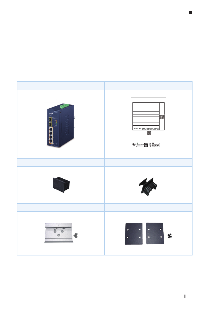
Industrial Gigabit PoE+ Switch x 1 User’s Manual Sheet x 1
Let’s get started with your PLANET product
IGS-624HPT
EN Please scan the QR code to browse our online User’s Manual or Quick
Installation Guide and follow the instructions to complete the setup.
User's Manual
DE
Bitte scannen Sie den QR- Code sie werden per Browser zur
Bedienungsanleitung oder Schnellanleitung weiter geleitet. Folgen Sie den
Anweisungen um die Installation abzuschließen.
FR
Veuillez scanner le code QR pour obtenir notre Notice d’Utilisation en
ligne ou notre Guide d’Installation Rapide et suivez les instructions pour
compléter la conguration
ES
Escanee el código QR para encontrar el Manual del Usuario en línea o
la Guía de Instalación Rápida y siga las instrucciones para completar la
conguración.
IT Scansiona il codice QR per consultare online il Manuale utente o la Guida di
installazione rapida e segui le istruzioni per completare la congurazione.
PT Por favor, escaneie o QR code para navegarno Manual do Usuário ou Guia
de Instalação Rápida. Siga as instruções para completar a conguração.
PL
Zeskanuj kod QR, aby otworzyć naszą internetową instrukcję obsługi
lub instrukcję szybkiej instalacji. Postępuj zgodnie z instrukcjami, aby
zakończyć poprawną kongurację.
RU
One word modify: Отсканируйте QR-код, чтобы просмотреть наше
онлайн-руководство пользователя или руководство по быстрой
настройке, и следуйте инструкциям для завершения настройки
RO Te rugam sa scanezi codul QR, pentru a descarca User’s Manual sau Quick
Installation Guide si a urmari instructiunile necesare in nalizarea instalarii
AR
Need more help?
PLANET online FAQs:
http://www.planet.com.tw/en/support/faq
Copyright © PLANET Technology Corp. 2023.
Contents are subject to revision without prior notice.
PLANET is a registered trademark of PLANET Technology Corp.
All other trademarks belong to their respective owners.
Part No. 2360-AH0590-000
SFP Dust Cap x 2 RJ45 Dust Cap x 4
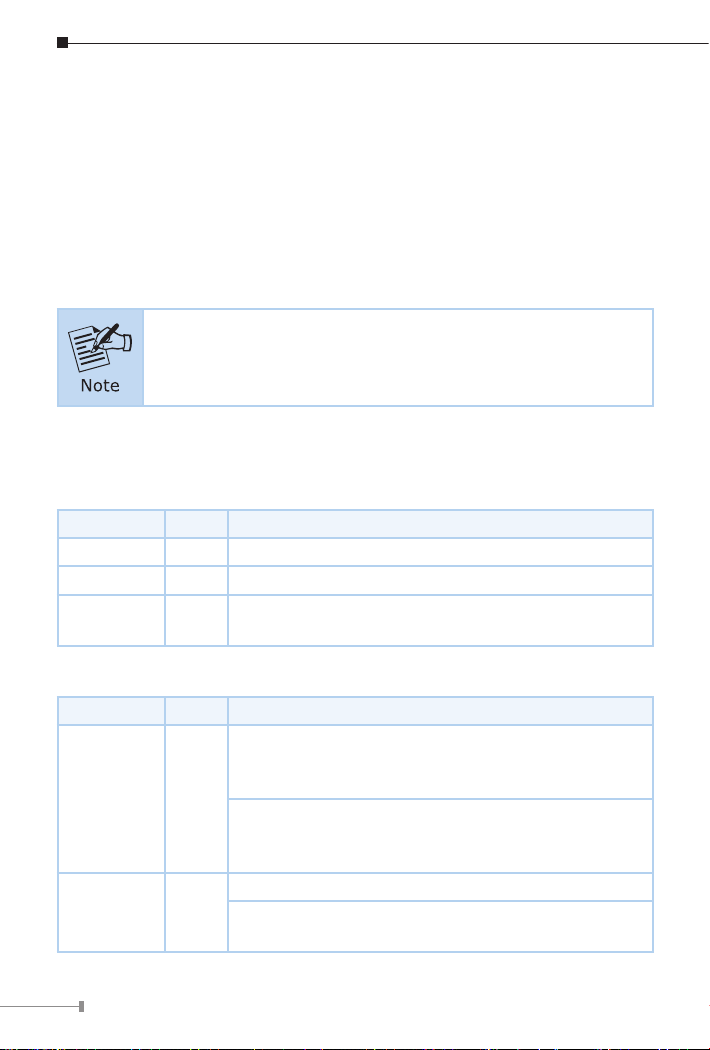
DIN-rail Kit Wall-mounting Kit
If any of these are missing or damaged, please contact your dealer
immediately; if possible, retain the carton including the original packing
material, and use them again to repack the product in case there is a need to
return it to us for repair.

4
2. Hardware introduction
2.1 Switch Front Panel
The front panel of the Industrial Gigabit PoE+ Switch consists of Ethernet
interfaces and LED indicators.
Front View
120W
PoE Usage
90W
60W
30W
4
6
5
3
2
1
LNK ACT
PoE-in-Use
1000
100/2500
LNK/ACT
LNK/ACT
IGS-624HPT
Redundant
Switch
P1 P2 Alarm
Fiber Mode
Figure 1: IGS-624HPT Front View
PoE Power Usage LED
The front panel of the Industrial Gigabit PoE+ Switch has four LEDs which
indicate PoE Power Usages of 30W, 60W, 90W and 120W. With these LED
indications, you can monitor the current PoE power in use status of Industrial
GigabitPoE+Switcheasilyandeciently.
120W
PoE Usage
90W
60W
30W

5
DIP Switch
The front panel of the Industrial Gigabit PoE+ Switch provides one DIP Switch
whichisforconguringberredundantfunction.
The DIP Switch settings and descriptions:
Redundant
Switch
Fiber Mode
Fiber Mode
(DIP Switch)
Switch
(Default Mode)
This mode allows the Industrial Gigabit PoE+
Switch to use 6 ports.
Redundant
This mode allows one of the two SFP ports to
be redundant while the other 5 ports are in
operation.
Redundancy Overview
The Industrial Gigabit PoE+ Switch provides rapid ber redundancy of link for
highly critical Ethernet applications; the redundant mode supports auto-recover
function. If the link of the destination port of a packet is down, it will forward
thepackettotheother port of thebackuppair.Thefollowinggure shows the
redundant functions.
Main Primary
Backup
Redundancy
< Primary Port >
Link Status : Up
Traffic Flow : Forwarding
< Backup Port >
Link Status : Down
Traffic Flow : Blocking
Main Primary
Backup
Redundancy
< Primary Port >
Link Status : Down
Traffic Flow : N/A
< Backup Port >
Link Status : Up
Traffic Flow : Forwarding
Traffic is changed from Primary Port to Backup Port
Figure 2: Redundancy Behavior Topology

6
zAuto-detects link status and redundant dual ports with the same connector
type
zWhen Primary Port is active, the Backup Port is blocked.
zWhenPrimaryPortlinkfails,thetracswapstoBackupPortautomatically.
zOncethePrimaryPortstatusisconnected, thetracwillswap fromBackup
Port to Primary Port.
zUsing the Redundant mode, port 5 is dened as Primary Port and port 6 as
Backup Port.
Using the Redundant mode, port 5 is defined as Primary
Port and port 6 as Backup Port.
2.2 LEDDenition:
System
LED Color Function
P1 Green Light: Indicates power 1 has power.
P2 Green Light: Indicates power 2 has power.
Alarm Red Light: Indicates either power 1 or power 2 has no
power.
Per 802.3at PoE+10/100/1000BASE-T Interface (Port 1 to Port 4)
LED Color Function
LNK/ACT Green
Light: Indicates the Industrial Gigabit PoE+
Switch is successfully connecting to the network at
10/100/1000Mbps.
Blink: Indicates that the Industrial Gigabit PoE+
Switch is actively sending or receiving data over that
port.
PoE-in-Use Amber
Light: Indicates the port is providing DC in-line power.
O: Indicates the connected device is not a PoE
powered device (PD).

7
Per 100/1000/2500BASE-X Interface (Port 5 to Port 6)
LED Color Function
1000
LNK/ACT Green
Light: Indicates the port is running at 1000Mbps and
successfully established.
Blink: Indicates that the Industrial Gigabit PoE+
Switch is actively sending or receiving data over that
port.
100/2500
LNK/ACT Amber
Lights to indicate the port is successfully established
at 100/2500Mbps
Blinks to indicate that the Switch is actively sending
or receiving data over that port.
Per PoE Power Usage (Unit: Watt) (Lower LED to upper LED)
LED Color Function
30W Amber
O to indicate the PoE usage is less than 14W.
Blinks to indicate that the PoE usage is around 15W
to 29W.
Lights to indicate the PoE usage is around/over 30W.
60W Amber
Blinks to indicate that the PoE usage is around 45W
to 59W.
Lights to indicate the PoE usage is around/over 60W.
90W Amber
Blinks to indicate that the PoE usage is around 75W
to 89W.
Lights to indicate the PoE usage is around/over 90W.
120W Amber
Blinks to indicate that the PoE usage is around 100W
to 119W.
Lights to indicate the PoE usage is at the maximum.

8
2.3 Switch Upper Panel
The upper panel of the Industrial Gigabit PoE+ Switch consists of one terminal
block connector within two DC power inputs. Figure 3 shows the upper panel
of the Industrial Gigabit PoE+ Switch.
DC Input:
12-54V , 7A max.
V1+ V2+
PWR1 Alarm PWR2
Max. Fault Alarm Loading: 24V, 1A
1 2 3 4 5 6
Figure 3: Industrial Gigabit PoE Switch Upper Panel
2.4 Wiring the Power Inputs
The 6-contact terminal block connector on the top panel of Industrial Gigabit
PoE+ Switch is used for two redundant power inputs. Please follow the steps
below to insert the power wire.
When performing any of the procedures like inserting the wires
or tightening the wire-clamp screws, make sure the power is
OFF to prevent from getting an electric shock.
1. Insert positive and negative DC power wires into contacts 1 and 2 for
POWER 1, or contacts 5 and 6 for POWER 2.
DC Input:
12-54V , 7A max.
V1+ V2+
PWR1 Alarm PWR2
Max. Fault Alarm Loading: 24V, 1A
1 2 3 4 5 6
V1+ V1- V2+ V2-

9
2. Tighten the wire-clamp screws for preventing the wires from loosening.
123456
Power 1 Alarm Power 2
V+ V- V+ V-
PWR1 and PWR2 must provide the same DC voltage for power
load balance while operating with dual power input.
2.5 Wiring the Faulty Alarm Contact
The faulty alarm contacts are in the middle of the terminal block connector
as the picture shows below. Inserting the wires, the Industrial Gigabit PoE+
Switch will detect the fault status of the power failure and then forms an open
circuit. The following illustration shows an application example for wiring the
faulty alarm contacts.
Faulty Alarm Contacts
The Faulty Alarm Contacts are
energized (CLOSE) for normal
operation and will OPEN when
failure occurs
Alarm
1 2 3 4 5 6
Insert the wires into the fault alarm contacts

10
1. The wire gauge for the terminal block should be in the range
of 12 ~ 24 AWG.
2. Alarm relay circuit accepts up to 24V, max. 1A currents.
2.6 Grounding the Device
Users MUST complete grounding wired with the device; otherwise, a sudden
lightning could cause fatal damage to the device.
DC Input:
12-54V , 7A max.
V1+ V2+
PWR1 Alarm PWR2
Max. Fault Alarm Loading: 24V, 1A
1 2 3 4 5 6
Earth Ground
EMD (Lightning) DAMAGE IS NOT COVERED UNDER WARRANTY.

11
3. Installation
This section describes the functionalities of the Industrial Gigabit PoE+ Switch’s
components and guides you to installing it on the DIN rail and wall. Please
read this chapter completely before continuing.
The following pictures show how to install the device. However,
the device in the picture is not IGS-624HPT.
3.1 DIN-rail Mounting Installation
1
2
3.2 Wall-mount Plate Mounting

12
3.3 Side Wall-mount Plate Mounting
When performing any of the procedures like inserting the wires
or tightening the wire-clamp screws, make sure the power is
OFF to prevent from getting an electric shock.

13
4.ProductSpecications
This section describes the functionalities of the Industrial Gigabit PoE+ Switch’s
components and guides you to installing the Switch.
Model IGS-624HPT
HardwareSpecications
Copper Ports 4 10/100/1000BASE-T RJ45 auto-MDI/MDI-X ports
PoE Injector Ports Four ports with 802.3at PoE+ injector function
(Port 1 to Port 4)
SFP Slots
(Auto Detection)
Two 1000/2500BASE-SX/LX/BX SFP interface
(Port 5 to Port 6)
Compatible with 100BASE-FX SFP
DIP Switch Switch(default)/berredundantmode
Connector
Removable 6-pin terminal block
Pin 1/2 for Power 1;
Pin 3/4 for fault alarm;
Pin 5/6 for Power 2
Power Requirements 12~54V DC, 7A (max.)
Redundant power with reverse polarity protection
Alarm Provides one relay output for power failure
Alarm relay current carry ability: 1A @ 24V DC
Power Consumption
Max. 7.56 watts/25.77BTU
(Ethernet Full Loading)
Max. 140 watts/477.4BTU
(Ethernet + PoE Full Loading)
Dimensions
(W x D x H) 50 x 87 x 135 mm
Weight 635g
Enclosure IP40 metal case
Installation DIN-rail kit and wall-mount kit
ESD Protection 6KV

14
LED
System:
Power 1 (Green)
Power 2 (Green)
Fault Alarm (Red)
Per 10/100/1000T RJ45 PoE+ Ports (Port 1~Port 4)
LNK/ACT (Green)
PoE-in-Use (Amber)
Per SFP Interface: (Port 5~Port 6)
1000 LNK/ACT (Green)
100/2500 LNK/ACT (Amber)
PoE Usage:
30W, 60W, 90W, 120W (Amber)
SwitchSpecications
Switch Architecture Store-and-Forward
Switch Fabric 18Gbps
Throughput
(packet per second) 13.39Mpps@64bytes
Address Table 4K entries
BuerMemory 1Mbitson-chipbuermemory
Jumbo Frame 12.2Kbytes
Flow Control Back pressure for half duplex
IEEE 802.3x pause frame for full duplex
Power over Ethernet
PoE Standard IEEE 802.3af Power over Ethernet
IEEE 802.3at Power over Ethernet Plus PSE
PoE Power Supply Type End-span
Power Pin Assignment 1/2(+), 3/6(-)
PoE Power Output
IEEE 802.3af Standard
- Per port 48V~51V DC (depending on the power
supply), max. 15.4 watts
IEEE 802.3at Standard
- Per port 51V~54V DC (depending on the power
supply), max. 36 watts

15
PoE Power Budget
(max.)
60W@12V DC input
90W@24V DC input
120W@48V-54V DC input
Max. Number of Class
4 PDs 4
Standards Conformance
Regulatory Compliance FCC Part 15 Class A, CE
Stability Testing
IEC 60068-2-32 (free fall)
IEC 60068-2-27 (shock)
IEC 60068-2-6 (vibration)
Standards Compliance
IEEE 802.3 Ethernet
IEEE 802.3u Fast Ethernet
IEEE 802.3ab Gigabit Ethernet
IEEE 802.3az Gigabit SX/LX
IEEE 802.3x Full-Duplex Flow Control
IEEE 802.3af Power over Ethernet
IEEE 802.3at Power over Ethernet Plus PSE
IEEE 802.1p Class of Service
Environment
Temperature Operating: -40~75 degrees C
Storage: -40~75 degrees C
Humidity
(non-condensing)
Operating: 5~90%
Storage: 5~90%

16
5. Customer Support
Thank you for purchasing PLANET products. You can browse our online FAQ
resource on PLANET web site rst to check if it could solve your issue. If you
need more support information, please contact PLANET switch support team.
PLANET online FAQs:
http://www.planet.com.tw/en/support/faq
Switch support team mail address:
Copyright © PLANET Technology Corp. 2023.
Contents are subject to revision without prior notice.
PLANET is a registered trademark of PLANET Technology Corp.
All other trademarks belong to their respective owners.

17
FCC Warning
This equipment has been tested and found to comply with the regulations for
a Class A digital device, pursuant to Part 15 of the FCC Rules. These limits
are designed to provide reasonable protection against harmful interference
when the equipment is operated in a commercial environment. This equipment
generates, uses, and can radiate radio frequency energy and, if not installed
and used in accordance with this user’s guide, may cause harmful interference
to radio communications. Operation of this equipment in a residential area is
likely to cause harmful interference, in which case the user will be required to
correct the interference at his own expense.
CE Mark Warning
This device is compliant with Class A of CISPR 32. In a residential environment
this equipment may cause radio interference.
WEEE Warning
To avoid the potential eects on the environment and human health
as a result of the presence of hazardous substances in electrical and
electronic equipment, end users of electrical and electronic
equipment should understand the meaning of the crossed-out
wheeled bin symbol. Do not dispose of WEEE as unsorted municipal waste and
have to collect such WEEE separately.
Table of contents
Other Planet Switch manuals

Planet
Planet GSD-1222VHP User manual

Planet
Planet WGSW-52040 User manual

Planet
Planet FSD-808HP User manual

Planet
Planet GSW-2401 User manual

Planet
Planet GSD-1020 User manual

Planet
Planet SW-502 User manual

Planet
Planet XGS-6350-12X8TR User manual

Planet
Planet GSD-1008HP User manual

Planet
Planet GSD-1002M User manual

Planet
Planet FSD-808P User manual

Planet
Planet FSD-1605 User manual

Planet
Planet FGSW-008 User manual

Planet
Planet IGS-5225-4T2S User manual

Planet
Planet POE-1200G User manual

Planet
Planet WGSW-24000 User manual

Planet
Planet KVM-210 M Series User manual

Planet
Planet HPOE-460 User manual

Planet
Planet GSD-800 User manual

Planet
Planet FSD-804PS User manual

Planet
Planet FGSW-2612PVS User manual