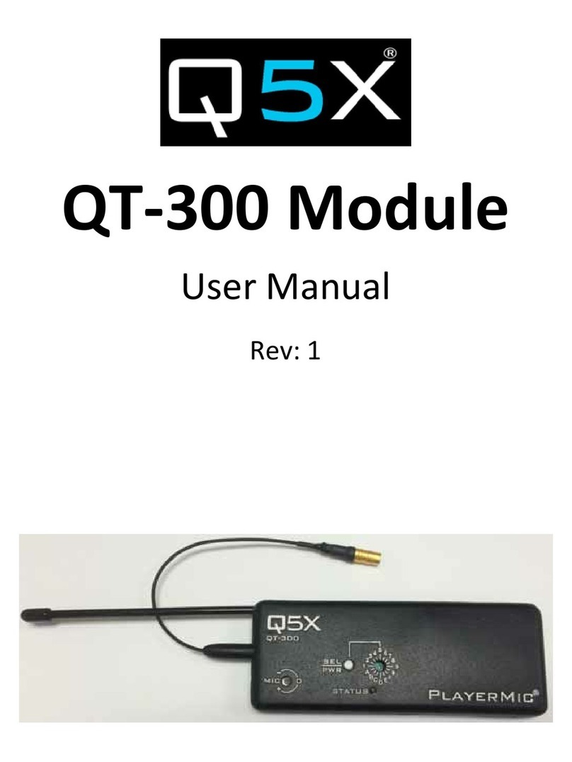
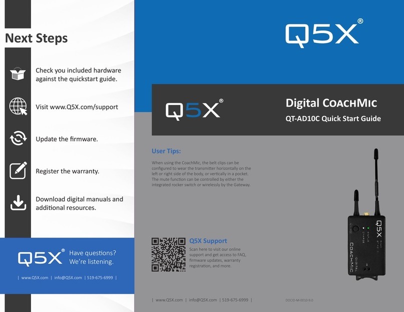
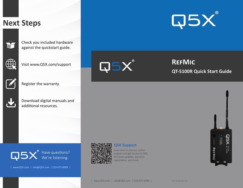
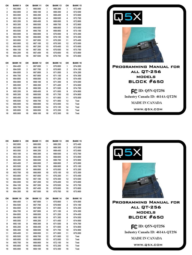
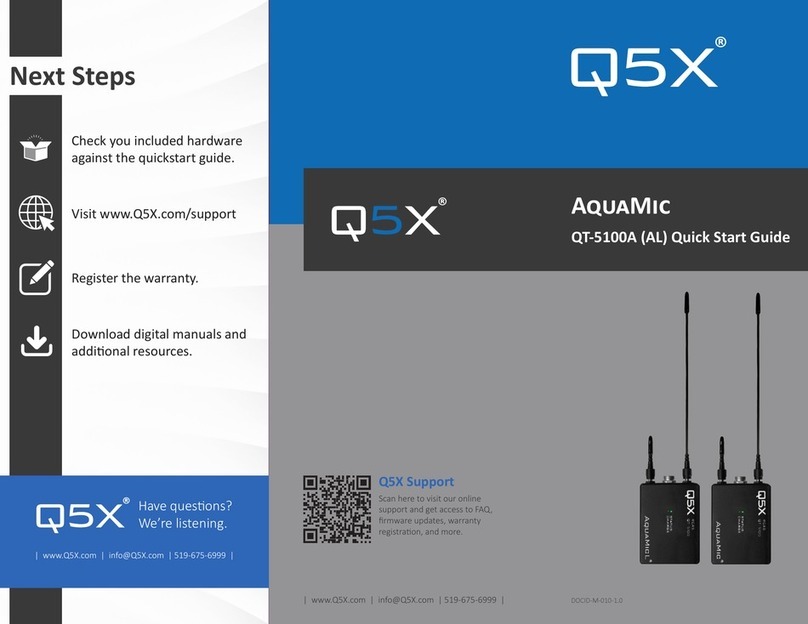
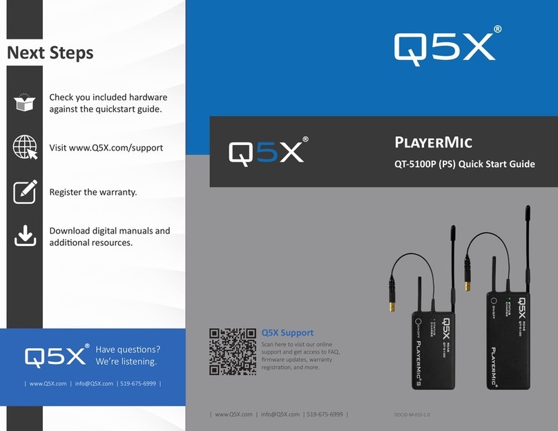
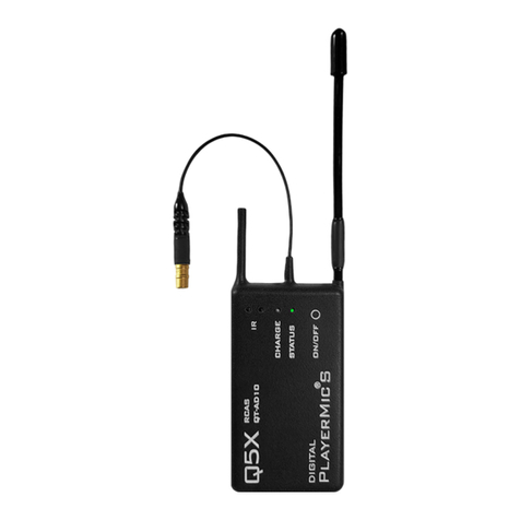
Q5X QT-5100 User manual

QT-5100 Series
User Manual
Rev: 2.0
DOCID-M-006-0

CONTENTS
SECTION 1
OVERVIEW
• DOCUMENT DESCRIPTION
• MANUAL REVISION HISTORY
03
SECTION 2
REGULATORY INFORMATION
04 - 06
SECTION 3
INTRODUCTION
07 - 08
SECTION 4
POWER MANAGEMENT
• CHARGING
• STORAGE MODE
• STANDBY MODE
• ON MODE
09 - 10
SECTION 5
MC
• START-UP
• SETTINGS
• ACTIVE TRANSMITTERS LIST
• GROUP COMMANDS
• DEVICE CONFIGURATION
• TOOLS
11 - 17
SECTION 6
LED STATUS
• LED STATUS TABLES
18- 19
SECTION 8
SPECIFICATIONS
21- 22
SECTION 10
FIRMWARE UPDATES
24
SECTION 11
HARDWARE DIAGRAMS
25- 26
SECTION 13
CONTACT INFORMATION
31
SECTION 12
QUICK START GUIDES
27- 30
SECTION 9
LICENSING INFORMATION
23
SECTION 7
RECEIVER
• COMPATIBILITY MODES
20

3
Overview
Rev 1.0 June 8, 2020 Original.
DOCUMENT DESCRIPTION
This manual describes the operaon of the analog transmiers in the QT-5100 Family: PlayerMic, CoachMic,
AquaMic, RefMic, RefMic HD and Incognito. All transmiers operate in conjuncon with:
• A microphone with a compable Lemo connector.
• A compable receiver
• Q5X Gateway (remote control).
• Handheld MicCommander (QG-H2).
• Network Gateway (QG-N3).
Upon delivery, visit www.Q5X.com/support to:
• Register the warranty.
• Download manuals.
MANUAL REVISION HISTORY

4
FCC NOTICES
:
This device complies with Part 15 of the FCC Rules. Operaon is subject to the following two condions:
1. This device may not cause harmful interference.
2. This device must accept any interference received, including interference that may cause undesired operaon.
This equipment has been tested and found to comply with the limits for a Class B digital device, pursuant to part
15 of the FCC Rules. These limits are designed to provide reasonable protecon against harmful interference in a
residenal installaon. This equipment generates, uses and can radiate radio frequency energy and, if not installed
and used in accordance with the instrucons, may cause harmful interference to radio communicaons. However,
there is no guarantee that interference will not occur in a parcular installaon. If this equipment does cause
harmful interference to radio or television recepon, which can be determined by turning the equipment o and
on, the user is encouraged to try to correct the interference by one or more of the following measures:
• Reorient or relocate the receiving antenna.
• Increase the separaon between the equipment and receiver.
• Connect the equipment into an outlet on a circuit dierent from that to which the receiver is connected.
• Consult the dealer or an experienced radio/TV technician for help.
Warnings:
Wireless microphone users shall rely on the white space databases in part 15, Subpart H to determine that their
intended operang frequencies are available for unlicensed wireless microphone operaon at the locaon where
they will be used. Wireless microphone users must register with and check a white space database to determine
available channels prior to beginning operaon at a given locaon. A user must re-check the database for available
channels if it moves to another locaon. Changes or modicaons not expressly approved by Quantum5X
Systems Inc, could void the user’s authority to operate the equipment. This module has been designed to operate
with only the supplied integrated antenna or the supplied SSMA antenna for the 802.15.4 Radio. Replacing or
modifying these antennas is strictly prohibited.

5
This device contains license-exempt transmier(s)/
receiver(s) that comply with Innovaon, Science and
Economic Development Canada’s license-exempt
RSS(s). Operaon is subject to the following
two condions:
1. This device may not cause interference.
2. This device must accept any interference,
including interference that may cause undesired
operaon of the device.
:
This radio transmier IC:4614A-QT5100 has been
approved by Innovaon, Science and Economic
Development Canada to operate with the antenna
types listed below, with the maximum permissible
gain indicated. Antenna types not included in this
list that have a gain greater than the maximum gain
indicated for any type listed are strictly prohibited
for use with this device.
This device operates on a no-interference,
no-protecon basis. Should the user seek to obtain
protecon from other radio services operang in
the same TV bands, a radio license is required. For
further details, consult Innovaon, Science and
Economic Development Canada’s Client Procedures
Circular CPC-2-1-28, Voluntary Licensing of
License-Exempt Wireless Microphones in the
TV Bands.
L’émeeur/récepteur exempt de licence contenu
dans le présent appareil est conforme aux
CNR d’Innovaon, Sciences et Développement
économique Canada applicables aux appareils radio
exempts de licence. L’exploitaon est autorisée aux
deux condions suivantes:
1. L’appareil ne doit pas produire de brouillage.
2. L’appareil doit accepter tout brouillage
radioélectrique subi, même si le brouillage
est suscepble d’en compromere le
fonconnement.
:
4614A-QT5100 a été approuvé par Innovaon,
Sciences et Développement économique Canada
pour fonconner avec les types d’antenne énumérés
ci dessous et ayant un gain admissible maximal.
Les types d’antenne non inclus dans cee liste, et
dont le gain est supérieur au gain maximal indiqué
pour tout type gurant sur la liste, sont strictement
interdits pour l’exploitaon de l’émeeur.
Ce disposif fonconne selon un régime de non-
brouillage et de non-protecon. Si l’ulisateur
devait chercher à obtenir une certaine protecon
contre d’autres services radio fonconnant dans
les mêmes bandes de télévision, une licence
radio serait requise. Pour en savoir plus, veuillez
consulter la Circulaire des procédures concernant
les clients CPC-2-1-28, Délivrance de licences sur
une base volontaire pour les microphones sans l
exempts de licence exploités dans les bandes de
télévision d’Innovaon, Sciences et Développement
économique Canada.

6
RF Exposure Compliance:
The QT-5100 module is granted with a modular approval for portable applicaons. The module is to be
used by Quantum5X in their nal products without addional FCC/ISED cercaon if they meet the
cercaon condions.
Module Integraon into Host End Products:
The QT-5100 module transmier has been designed by Quantum5X Systems Inc. to be used by Quantum5X
as a building block for their wireless audio transmier products. The module, as designed, is a standalone unit
that is ready for integraon into nal form factor with the limitaon for mobile use as specied in RF Exposure
compliance. For proper usage of the module, the module integrator must ensure that the input power and input
audio signal do not exceed the specied limits as outlined in the specicaon secon. Failure to do so will result
in damage to the module. Final product(s) aer integraon with this module shall be tested to comply with all
applicable FCC requirements and Unintenonal radiators (FCC secon 15.107, 15.109 and ISED ICES-003) before
declaring compliance to Part 15 of the FCC Rules and ISED ICES-003.
The module integrator may not do the following. Failure to comply with these restricons will result in violaon of
the FCC cercaon.
1. Alter, modify or remove the module case.
2. Make changes to the Circuit Card Assembly of the module.
3. Remove, change or alter the integrated UHF antenna or the 802.15.4 antenna.
Labelling of the End Products:
The modular transmier must be equipped with either a permanently axed label.
The modular transmier must be labelled with its own FCC idencaon number,
and if the FCC idencaon number is not visible when the module is installed
inside another device, then the outside of the device into which the module is
installed must also display a label referring to the enclosed module. This exterior
label can use wording such as the following: ‘‘Contains Transmier Module” or
‘‘Contains “. Any similar wording that expresses the same meaning may be used.
Sample labels, that must be used for the module and the product, are shown on
the right.
Antenna / Connector Type Manufacturer Connector Type Max Gain
¼” Wire Antenna Q5X MHF-4L UHF 0 dBi, 2.45GHz 2 dBi
SSMA ¼” Whip Antenna Sam Woo Electronics MHF-4L- SSMA UHF 0 dBi, 2.45GHz 2 dBi

7
TRANSMITTERS
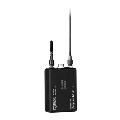
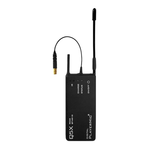
The QT-5100 series transmiers are rugged, small, at least sweatproof and have long baery life. In addion, the
AquaMic is waterproof (IP-68 cered to 100’) and the PlayerMic is exible.
The Q5X remote control system is referred to as Remote Control Audio System (RCAS). The RCAS manages the
transmier sengs rather than having sengs adjusted on the transmiers. RCAS operates via RF and transmits
though walls, clothing, uniforms, costumes and over longer distances than non-RF types of transmier control.
Remote operaon eliminates the need to physically handle the transmiers aer they are installed on the user.
The RCAS is available in 2 gateway formats described below; Handheld MicCommander (QG-H2) or Network
Gateway (QG-N3). Either format can be connected to MicControl soware to allow the interface to manage up to
100 transmiers on a computer. The Network Gateway can be used to setup dierent control zones or to extend
the control range of the RCAS System. RCAS allows the user to view, monitor and adjust any transmier within
the control range, specically:
• The transmier power state (ON or STBY) to conserve baery life when not in use.
• RF power and UHF frequency in the event of RF interference.
• Mic mute and mic gain.
• Transmier naming and grouping for easy control.
The QG-H2 MicCommander is a handheld, stand-alone device used to control up to 32 transmiers (as well as
legacy analog QT-5000 and digital QT-AD10 transmiers). A transmier can be remotely congured using the
simple interface of the MicCommander without physical access to the transmier. The MicCommander operates
independently from any other gateway or computer but can be connected to a computer by a USB cable to ulize
MicControl soware. It can override any seng made by the MicControl soware and vice versa.

8
The RCAS system can also be networked by ethernet using a QG-N3 Network Gateway to remotely control QT-
5100, AD10, and legacy analog transmiers ulizing MicControl soware running from a computer on the same
network. Mulple QG-N3 gateways can be added to an ethernet network to manage large venue installaons.
The QG-N3 is powered through a power over ethernet (PoE) switch or by a micro USB power supply.
MICCONTROL
MicControl is a Windows based soware program used to conveniently setup and control QT-5100 transmiers
through a friendly Graphical User Interface (GUI). This is parcularly useful when dealing with installaons of
mulple transmiers. MicControl can comfortably control up to 100 transmiers and can be connected to
mulple QG-N3 Network Gateways via ethernet and QG-H2 MicCommanders via USB to cover large venues.
MICROPHONE
QT-5100 uses a 1-pin Lemo connector for the PlayerMic, RefMic, RefMicHD, BeltMic and Incognito and a 6-pin
waterproof Lemo connector for the AquaMic. Microphone selecon should be made with care as microphones
with poor shielding are suscepble to RF noise caused by the transmission of the audio and 2.4 GHz control signal.

9
All transmiers have rechargeable lithium polymer baeries with run mes that vary from 2 - 16 hours depending
on power level and baery sizes. The values in this table are typical of new baeries.
.
Feature
AquaMic Waterproof Anodized
Aluminum
AquaMic: 65mm x
46mm x 19mm
AquaMic L:
65mm x 46mm x
22.5mm
AquaMic = 8
AquaMic L = 16
AquaMic = 4
AquaMic L = 8
PlayerMic Flexible Rubber
PlayerMic S:
74.5mm x 42mm x
11.5mm
PlayerMic:
97.5mm x 42mm x
11.5mm
PlayerMic = 8
PlayerMic S = 4
PlayerMic = 4
PlayerMic S = 2
CoachMic Mute Switch Nylon 65.5mm x 42mm
x 18.5mm 8 4
RefMic Mute Switch Nylon 99mm x 42mm x
9.4mm 8 4
RefMic HD
Mute Switch
Mic connector shield
Nylon 66.5mm x
57.5mm x 20mm 8 4
Incognito* 2 part,
concealable Rubber 47.5mm x 43mm
x 10.5mm 8 4
BeltMic Smallest Volume Nylon
53.5mm
x 42mm x
18.5mm
8 4

10
CHARGING
It is best to completely charge the QT-5100 before use. To charge a transmier, insert the supplied micro USB
charging cable and connect to a USB power source (QT-5100 should NOT be connected to a computer and should
be connected with a charge only cable.). For the AquaMic, the charge/data dongle needs to be aached between
micro USB charger and the AquaMic. The charge light will turn from red and to green once the unit is charged. If
the charge LED is ashing green/red, there is a charging error. If this happens check and or replace the charging
cable or the micro USB power supply. The baery will also not change if the baery temperature is below 0° C
or above 60° C. The baery charge level can be checked with a QG-H2 MicCommander or a QG-N3 gateway and
MicControl.
STORAGE MODE
When the QT-5100 transmier is in storage mode, the transmier will be completely o and will not respond
to any commands from the QG-H2 handheld MicCommander or QG-N3 Gateway. If the transmier is in storage
mode as opposed to a baery run down condion, when the charger is inserted it will wake up and report the
baery level via the <Charge> LED and the MicCommander. There are three ways to bring a QT-5100 out of
storage mode and into standby mode:
• Connect the transmier to a USB charger.
• Press the On/O buon for 3 seconds for any unit with the physical ON/OFF buon.
• Insert the reset key into the USB connector or charge/data dongle for the AquaMic, this will reset the TX and place the TX into storage
mode. Next plug in the charger to bring the TX out of storage mode.
STANDBY MODE
In standby mode, the transmier is transming a 2.4 GHz heartbeat every 1.5 seconds, and the transmier is not
transming the UHF carrier. The heartbeat contains conguraon data, such as RF frequency, output power and
mic oset. The heartbeat also contains status informaon such as baery level, mute status and 2.4 GHz channel.
In standby mode, the transmier will respond to commands to change parameters and to turn to the ON mode or
storage mode. Transmiers with an On/O buon (not AquaMic) enter standby in three ways:
• Entering the “STBY” command from the MicCommander status and control menu (this is the only way to enter standby for the
AquaMic since it does not have an On/O buon).
• 3 second hold of the On/O buon will toggle between ON and STBY.
• 12 second hold of the On/O buon will reset the transmier and return it to its prior mode.
ON MODE
In ON mode, the transmier is transming the UHF carrier and connuing to send 2.4 GHz heartbeats every 1.5
seconds. In this state the transmier will respond to commands to change parameters, and to turn to the standby
mode or storage mode.

11
MC
START-UP
Turn on the MicCommander by pressing the buon on the top of the unit. Upon powering up, the
MicCommander will display a list of transmiers to which it is currently registered. If the desired transmier is
not displayed on this Acve Transmiers list, it must be added.
SETTINGS
Select a transmier from the acve transmiers list
with the “ENTER” buon to view or edit its sengs.
When selected, the menu on the le will appear, the
menu on the right is accessed by selecng “Next”
:
Frequency can be adjusted by moving the cursor to the frequency value using the navigaonal
arrows then pressing “ENTER” buon. This will bring up the screen shown on the right.
To change the MHz values use the UP/DOWN arrows. To edit the frequency’s kHz, press the
“RIGHT” buon to highlight them then use the “UP/DOWN” arrows again. The “ENTER” or
“BACK” buon can be used to save changes. Select “Save” to conrm or “Cancel” to cancel.
Power:
From this locaon the transmier power can be set to ON or STBY.
:
Baery is the percentage of baery life remaining. The “CHG” to the le of the percentage denotes that the
device is currently charging.
:
Mic is the microphone state, either Live or Mute. Mung will turn the audio o and leave the transmier UHF
carrier on. This funcon can be used to remotely mute a mic on any QT-5100 transmier or to override a physical
mute switch on transmiers such as the QT-5100 CoachMic.

12
MC
:
Can be adjusted from -10 dB to +30 dB. The MicCommander displays this informaon in present.
Name:
Name is a 15-character alphanumeric name which can be entered for each transmier. Note that the receiver will
not display all 15 characters of the full transmier name.
:
Group is the group number (1-16) to which the transmier belongs, allowing it to be controlled with group
commands (see Group Commands below). To change the group to which the transmier belongs, select the
displayed group number and adjust it using the UP/DOWN arrows. Once sased, press the “ENTER” or “BACK”
buon and “Save” when prompted.
RF Power:
The TX output power can be adjusted from 10 mw, 25 mw, 50 mw and 100 mw. It is suggested to use the 50 mw
seng to maximize baery run me. (Selectable power values may vary by region.)
:
The RCAS control channel default is 25, change this on the transmier only if you are having control issues that
can be seen when you have completed a 2.4GHz spectrum scan. See Device Conguraon, the 2.4 GHz Channel
descripon in Link ID secon 3.5.
:
Storage Mode will disable all communicaon between the MicCommander and the transmier. To return to
standby mode, the On/O buon needs to be pressed for 3 seconds or the transmier needs to be connected to
a charger.

13
MC
:
Reboot will remotely cause the transmier to do a power on reset. This returns the transmier to its last known
state.
Main Menu:
The main Menu is accessed by pressing the “BACK” buon. From here you can navigate and select other menus,
including the “Transmiers” menu.
ACTIVE TRANSMITTERS LIST
:
Acve Transmiers menu will appear when rst turned on. A list of all transmiers currently registered with
the MicCommander will be displayed. The transmier list has seven separate tabs. Tab 1 is displayed inially
and indicated by the black line at the boom le of the screen. Addional tabs (shown below) are displayed
by pressing the right or le navigaon arrows. The RSSI and Link Status Icon are displayed to the le of the
transmier serial number. When a transmier is out of range or set to storage mode, data is displayed as series
of queson marks. From any of the Acve Transmier display tabs below, the transmier setup menu can be
accessed by pressing the “Menu” buon once the desired transmier has been highlighted. The Menu buon
will bring up a list of 15 items that are required for adding or removing a transmier from the acve transmier
menu, accessing special features of the selected transmier, or for sorng the Acve Transmier list.

14
MC
:
Transmiers can be added by scanning for all acve transmiers or by manually entering each transmier
serial number. To scan for all acve transmiers, select scan. Once the list has populated select the desired
transmiers and press the “Back” buon to load selected transmiers into the acve transmier list. Only
transmiers set to the same 2.4GHz channel and that have the same Link ID, or no Link ID will be able to be
scanned or added to the transmier acve list. To manually add transmiers, select “Add” and enter the
transmier serial number by scrolling up or down from the last entered number. To remove a transmier from
the acve list, select “Remove” or “Remove All”. “Remove” will remove the current selected transmier from the
acve list, “Remove All” will remove all transmiers in the acve list.
Linking:
Acvate or deacvate linking security for the selected transmiers in the acve transmier list. Seng the Link
ID of the MicCommander must be done under the Device Conguraon Menu. See Link ID secon 3.5 for more
details.
:
This feature will ash the Status LED very quickly 10 mes, which can help locate a transmier in a group of
transmiers.
:
Users can sort the Acve Transmier list by ve dierent variables: serial number, transmier name, RSSI,
transmier frequency and baery level. The list will remain sorted by the selected variable unl the QG-H2 or
QG-N3 is powered down. Users also have the opon of using the transmier serial number or the transmier
name as the device ID.
GROUP COMMANDS
Each transmier can be assigned to one of 16 groups from the transmier menu. Group seng allows a group
of transmiers to be turned to on or standby by a single command sent from the RCAS controller. This allows
for quick on or standby mes for a large group of transmiers, which is especially useful when sharing receive
frequencies between mulple transmiers during rst and second half of a sporng event or between acts of a
theatrical event.

15
MC
DEVICE CONFIGURATION
:
Linking is a process to securely create a “collecon” of RCAS devices that prevents unwanted access from RCAS
controllers outside of the collecon. Linking begins by seng Link ID on the MicCommander and then sending the
ID to all QT-5100 transmiers that will be part of the collecon. To expand the RCAS control network, the same
Link ID can also be shared between mulple MicCommanders (and other RCAS controllers). This allows addional
users to control the same collecon of linked transmiers. Steps:
• Select the Device Conguraon tab from the Main Menu and then select Link ID.
• Enter a 5-digit Link ID into the MicCommander manually or allow it to be auto-generated.
• Assign the same Link ID manually to addional MicCommanders if needed
• Link/unlink the transmiers:
• Highlight a desired transmier on the Acve Transmier list
• Press the “Menu” buon, scroll down the list of transmier features and select “Link”
• Selecng Un-Link will clear the Link ID from the QT-5100 transmier.
When the Link ID is cleared or set to 00000 any MicCommander can control that QT-5100 transmier.
• To clear a Link ID from a QT-5100 transmier where the Link ID has been forgoen or entered incorrectly,
plug and unplug the charger 3 mes in quick succession. This will put the transmier into recovery mode
for 2 minutes, indicated by the status LED ashing a RED/GREEN blinking paern. While in this mode the
QT-5100 transmits on all 2.4G channels, allowing the easy idencaon and pairing of transmiers and
MicCommanders that may be on dierent 2.4 GHz channels.
:
The RCAS control system operates in the ISM 2.4GHz RF spectrum with the 802.15.4 protocol and ulizes Zigbee
channels 11 to 26. In this menu, you can change the control channel if there is interference from nearby devices
that may be using similar technology like ZigBee or Bluetooth communicaons. It is very important to make sure
the MicCommander and the transmiers are on the same control frequency. Should you need to change the
RCAS channel due to interference, it is important to rst change all the transmiers you wish to control BEFORE
changing the MicCommander control channel. If a transmier is not on the same channel as the MicCommander
it will sll funcon as a UHF transmier but will not be “seen” by the MicCommander and cannot be controlled or
monitored.

16
MC
MC
DEVICE CONFIGURATION CON’T
:
Default is Channel 25 for RCAS as it is generally the channel with the least amount of interference. If the control
process seems to be borderline, go to Tools, enter the 2.4 Spectrum mode and view the local acvity on the
2.4GHz band.
:
It is important to ensure the QT-5100 transmier
and MicCommander are on the same control
channel. There are 16 pre-set channels which
can be used; 11 to 26.
They are 5 MHz apart and 2 MHz wide so there is
no overlap. The chart shows the channels and the
specic frequency for each.
:
The contrast level of the LCD display can be adjusted by selecng the value next to “LCD Contrast” and by pressing
the up and down arrows change the value.

17
MC
TOOLS
:
View the spectrum and idenfy the best channel to operate
the RCAS system on. Over me, the channel indicators will
store the peak values for easy reference. Lower bars
indicate less acvity which is the desired result. Select Reset
to clear the stored peak values to start a fresh scan.
:
Reserved for factory service funcons.

18
STATUS LED FLASHING
•
•
•
•
•
•
•
•
•
•
•
•
•
•
•
•
•
•
•
•

19
CHARGE LED
• Charging
•
• Charging error

20
COMPATIBILITY MODES
The QT-5100 Transmier family works with Q5X receivers as well as one other analog receivers from other wireless
manufacturers. The compability mode that was included was determined at the me of ordering.
For addional support contact Q5X for more info at: [email protected]
Other manuals for QT-5100
1
Table of contents
Other Q5X Transmitter manuals

Q5X
Q5X CoachMic QT-AD10C User manual

Q5X
Q5X QT-AD10A15 User manual

Q5X
Q5X QT-256 Owner's manual

Q5X
Q5X AquaMic QT-AD10A User manual

Q5X
Q5X PlayerMic User manual

Q5X
Q5X AquaMic QT-5100A User manual

Q5X
Q5X RefMic User manual

Q5X
Q5X QT-AD10 Series User manual

Q5X
Q5X QT-AD10 Series User manual

Q5X
Q5X QT-300 User manual