R&G FP0222BK User manual

R&G Racing
Unit 1, Shelleys Lane, East Worldham, Alton, Hampshire GU34 3AQ.
Tel: +44 (0)1420 89007 Fax +44 (0)1420 87301 www.rg-racing.com Email: info@rg-racing.com
PAGE 1 OF 10 FP0222BK
Picture A Picture B
FITTING INSTRUCTIONS FOR FP0222BK FORK PROTECTORS
KTM 790 ADVENTURE 2019
DIGITAL COPIES OF THESE INSTRUCTIONS ARE AVAILABLE FROM:
WWW.RG-RACING.COM
THIS KIT CONTAINS THE ITEMS PICTURED AND LABELLED OVER PAGE.
SOME PARTS MAY BE SHOWN FOR CLARITY OF INSTRUCTIONS ONLY.
DO NOT PROCEED UNTIL YOU ARE SURE ALL PARTS ARE PRESENT.
PLEASE READ ALL INSTRUCTIONS BEFORE PROCEEDING.
PLEASE NOTE THAT THE WAY THE KIT IS PACKED DOES NOT NECESSARILY REPRESENT THE WAY OF
MOUNTING TO THE BIKE.
IN THE EVENT OF RUBBER WASHERS BEING USED TO HOLD COMPONENTS ONTO BOLTS,
THESE RUBBER WASHERS CAN BE THROWN AWAY.

R&G Racing
Unit 1, Shelleys Lane, East Worldham, Alton, Hampshire GU34 3AQ.
Tel: +44 (0)1420 89007 Fax +44 (0)1420 87301 www.rg-racing.com Email: info@rg-racing.com
PAGE 2 OF 10 FP0222BK
TOOLS REQUIRED
• Socket Set to Include 13mm (x2), 27mm
and 32mm Sizes
• Wrench (x2)
• Torque Wrench
GENERAL TORQUE SETTINGS
M4 BOLT = 8Nm
M5 BOLT = 12Nm
M6 BOLT = 15Nm
M8 BOLT = 20Nm
M10 BOLT = 40Nm
M12 BOLT = 40Nm
LEGEND
ITEM
No.
DESCRIPTION QTY
ITEM 1 S1199 LHS CRASH PROTECTOR SPACER 1
ITEM 2 S1200 RHS CRASH PROTECTOR SPACER 1
ITEM 3 SB133 SPINDLE BAR (366mm LONG) 1
ITEM 4 B0213 CRASH PROTECTOR (WITH CS304 COMPRESSION SLEEVE FITTED) 2
ITEM 5 H0004 LHS REPLACEMENT SPINDLE NUT 1
ITEM 6 M8 NYLOC NUT 2
ITEM 7 M8 WASHER (19mm O/D) 2
EXPLODED ASSEMBLY DIAGRAM

R&G Racing
Unit 1, Shelleys Lane, East Worldham, Alton, Hampshire GU34 3AQ.
Tel: +44 (0)1420 89007 Fax +44 (0)1420 87301 www.rg-racing.com Email: info@rg-racing.com
PAGE 3 OF 10 FP0222BK
Picture 1 Picture 2
Picture 3 Picture 4
Picture 5 Picture 6

R&G Racing
Unit 1, Shelleys Lane, East Worldham, Alton, Hampshire GU34 3AQ.
Tel: +44 (0)1420 89007 Fax +44 (0)1420 87301 www.rg-racing.com Email: info@rg-racing.com
PAGE 4 OF 10 FP0222BK
FITTING INSTRUCTIONS
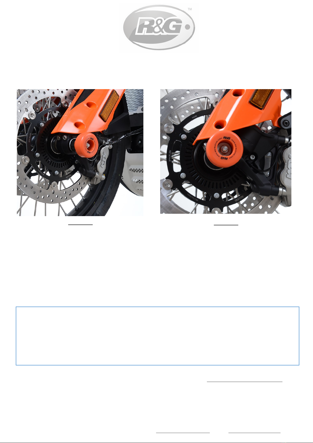
• Starting on the left-hand side of the motorcycle, remove the OEM spindle nut using a wrench fitted
with a 32mm socket, , as shown in picture 1.
• Using a wrench fitted with a 27mm socket, fit the replacement spindle nut (item 5) as shown in
picture 2, and tighten to the torque setting as specified by the manufacturer.
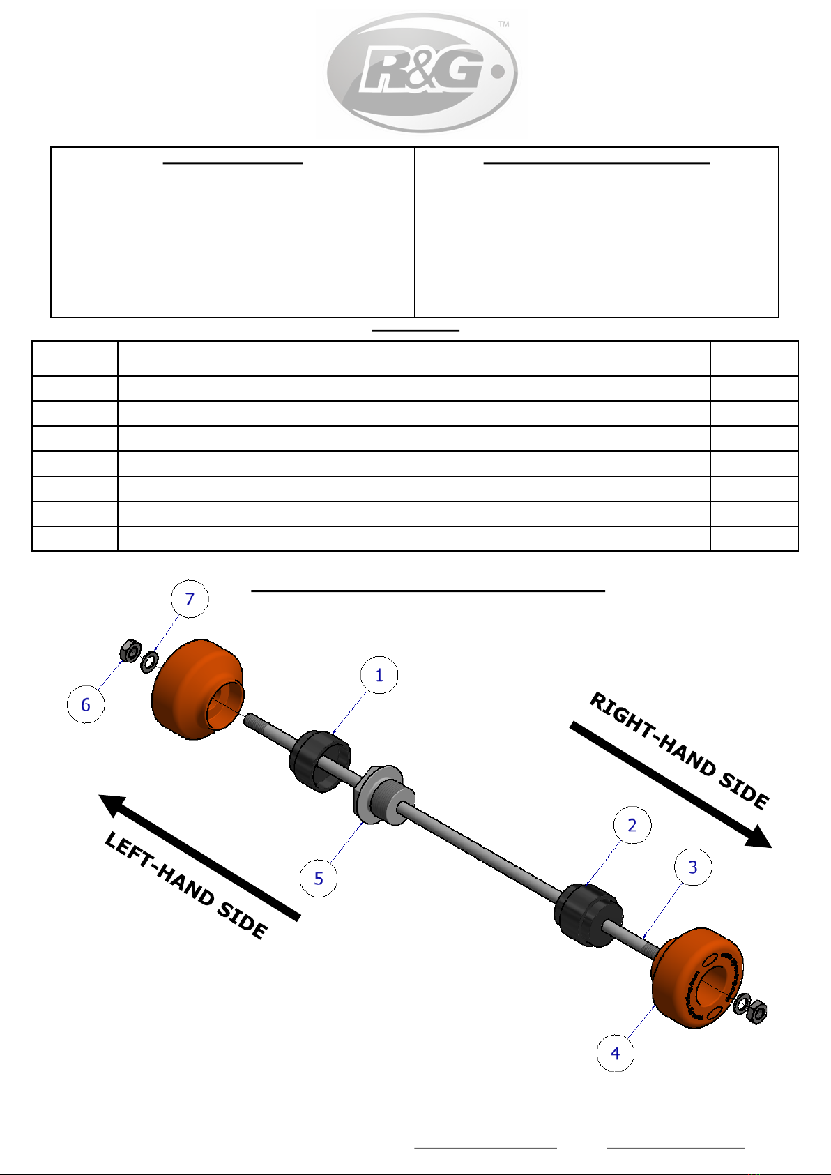
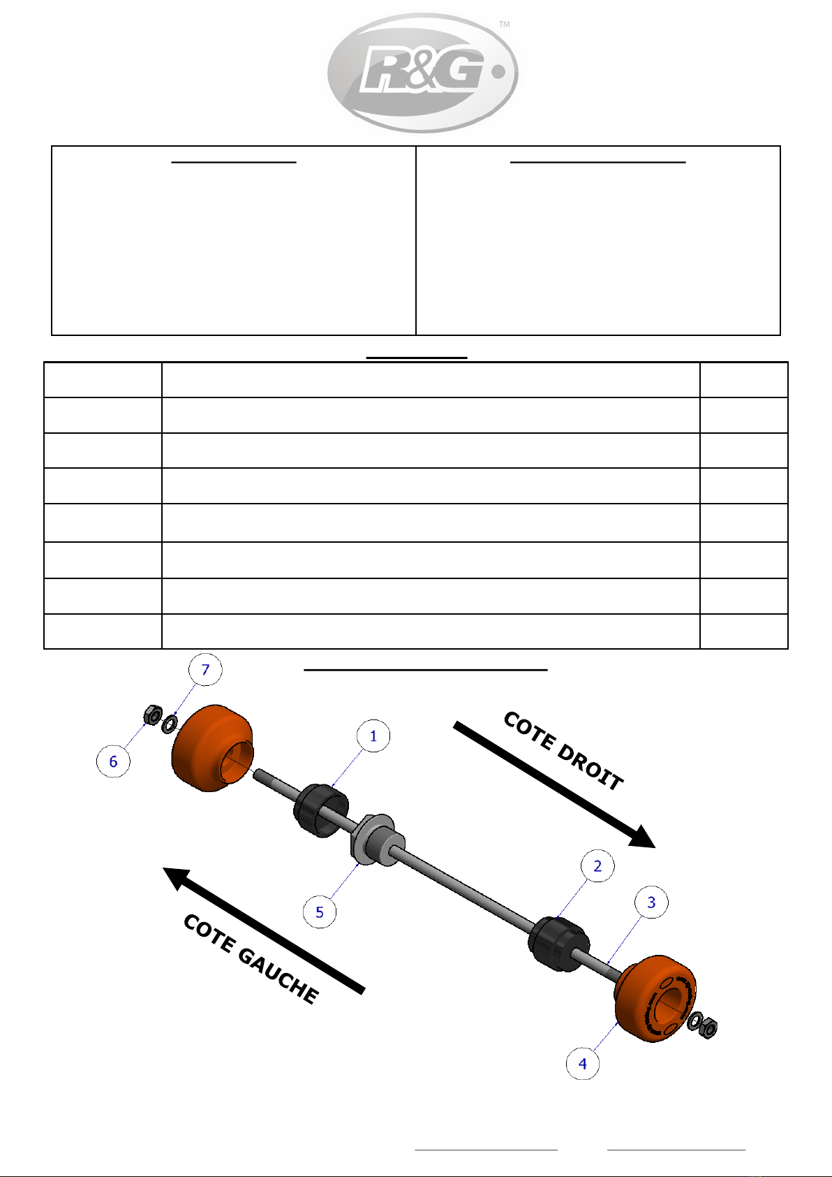
• Fit one nut (item 6) and one washer (item 7) to the spindle bar (item 3), engaging the nut so the
plastic insert of the nut is fully engaged and the bar protrudes by 1 or 2 threads. It is
recommended to use a small amount of superglue or Loctite to fix this nut as this will aid when
tightening the opposite side later.
• Moving to the right-hand side of the motorcycle, slide the smaller diameter end of the RHS crash
protector spacer (item 2) into the exposed spindle hole as shown in picture 3.
• Now, feed the spindle-bar with nut and washer through one of the crash protectors (item 4), then
pass this assembly through the RHS spacer so that the larger end of the spacer sits within the
crash protector and the spindle bar passes through the hole in the replacement spindle nut on the
LHS, as shown in picture 4.
• Slide the LHS crash protector spacer (item 1) over the spindle nut, then fit the remaining crash
protector (item 4) over the exposed end of the spindle bar on the LHS. Fit the remaining Nyloc nut
(item 6) and washer (item 7) from the kit onto the thread protruding from the crash protector.
• As shown in picture 5, tighten each nut on both sides evenly and ensure that the plastic insert of
both nuts are fully engaged and protruding threads are equal on both sides. Check the fork
protectors are secure and held firmly against the spacers and do not spin.
• Do not overtighten –the Nyloc nuts will hold it tight.
CONSUMER NOTICE
The catalogue description and any exhibition of samples are only broad indications of the Products and R&G may make design
changes which do not diminish their performance or visual appeal and supplying them in such state shall conform to the order.
The Buyer acknowledges no representation or warranty (other than as to title) has been given or will apply to the Products other
than those in R&G’s order or confirmation and the Buyer confirms it has chosen the Products as being of merchantable quality
and suitable for its particular purposes. Where R&G fits the Products or undertakes other services it shall exercise reasonable skill
and care and rectify any fault free of charge unless the workmanship has been disturbed. The Buyer is responsible for ensuring
that the warranty on the motorcycle is not affected by the fitting of the Products. On return of any defective Products R&G shall
at its option either supply a replacement or refund the purchase money but shall not be liable if the Products have been modified
or used or maintained otherwise than in accordance with R&G’s or manufacturer’s instructions and good engineering practice or if
the defect arises from accident or neglect. Other than identified above and subject to R&G not limiting its liability for causing
death and personal injury, it shall not be liable for indirect or consequential loss and otherwise its liability shall be limited to the
amounts paid by the Buyer for the Products or the fitting or service concerned. These terms do not affect the Buyer’s statutory
rights.
R&G RETURNS POLICY (NON-FAULTY GOODS)
Returns must be pre-authorised (if not pre-authorised the return will be rejected). Goods may only be returned direct to us if
they were purchased direct from us (customer must prove if necessary). Otherwise to be returned to original vendor. Goods
must be in re-sellable condition, in the opinion of R&G. All returns are subject to a 25% restocking and handling fee (25% of the
gross value exc. P&P –at the prevailing price at time of purchase). The customer must pay any and all carriage charges. No

R&G Racing
Unit 1, Shelleys Lane, East Worldham, Alton, Hampshire GU34 3AQ.
Tel: +44 (0)1420 89007 Fax +44 (0)1420 87301 www.rg-racing.com Email: info@rg-racing.com
PAGE 5 OF 10 FP0222BK
Photo A Photo B
NOTICE DE MONTAGE POUR FP0222BK PROTECTIONS FOURCHE
KTM 790 ADVENTURE 2019
NOTICE DISPONIBLE AU TÉLÉCHARGEMENT SUR : WWW.RG-RACING.COM
LEKIT CONTIENT LES ARTICLES EN PHOTO ET ETIQUETTES SUR LA PAGE
LES PARTIES PRESENTÉES PEUVENT ETRE UNIQUEMENT REPRESENTATIVES POUR LA CLARTE DES INSTRUCTIONS.
NEPAS PROCÉDER AU MONTAGE AVANT DE VOUS ÊTRES ASSURE QUE TOUTES LES PIECES SOIENT PRÉSENTES.
SVP, LIRE L’ENSEMBLE DE LA NOTICE AVANT DE PROCÉDER AU MONTAGE.
LAFAÇON DONT LE KIT EST EMBALLÉ NE CORRESPOND PAS FORCÉMENT ÀLA FAÇON DE MONTER LES
PIÈCES SUR LA MOTO .
NOTEZ QUE SI LES KITS SONT EMBALLÉS AVEC DES RONDELLES EN CAOUTCHOUC SERVANT ÀTENIR
LES COMPOSANTS, CES RONDELLES DOIVENT ÊTRE JETÉES.

R&G Racing
Unit 1, Shelleys Lane, East Worldham, Alton, Hampshire GU34 3AQ.
Tel: +44 (0)1420 89007 Fax +44 (0)1420 87301 www.rg-racing.com Email: info@rg-racing.com
PAGE 6 OF 10 FP0222BK
OUTILS REQUIS
• Clé à cliquet + douilles 13mm (x2), 27mm
et 32mm
• Clé à molette (x2)
• Clé dynamométrique
VALEURS DE SERRAGE
M4 BOULON = 8Nm
M5 BOULON = 12Nm
M6 BOULON = 15Nm
M8 BOULON = 20Nm
M10 BOULON = 40Nm
LEGENDE
ARTICLE No. DESCRIPTION QTE
ARTICLE 1 S1199 ENTRETOISE DE PROTECTION CRASH GAUCHE 1
ARTICLE 2 S1200 ENTRETOISE DE PROTECTION CRASH DROITE 1
ARTICLE 3 SB133 AXE MOYEU (366mm DE LONG) 1
ARTICLE 4 B0213 PROTECTION CRASH (AVEC CS304 MANCHON DE COMPRESSION
MONTE)
2
ARTICLE 5 H0004 ECROU MOYEU DE REMPLACEMENT GAUCHE 1
ARTICLE 6 M8 ECROU 2
ARTICLE 7 M8 RONDELLE (19mm O/D) 2
SCHEMA DE MONTAGE

R&G Racing
Unit 1, Shelleys Lane, East Worldham, Alton, Hampshire GU34 3AQ.
Tel: +44 (0)1420 89007 Fax +44 (0)1420 87301 www.rg-racing.com Email: info@rg-racing.com
PAGE 7 OF 10 FP0222BK
NOTICE DE MONTAGE
• En commençant du côté gauche de la moto, retirez l'écrou d’axe d’origine à l'aide d'une clé munie
d'une douille de 32 mm, comme indiqué sur la photo 1.
• À l'aide d'une clé à cliquet + douille de 27 mm, montez l'écrou d’axe de rechange (article 5)
comme indiqué sur la photo 2 et serrez au couple spécifié par le fabricant.
• Monter un écrou (article 6) et une rondelle (article 7) sur l’axe (article 3), en engageant l'écrou de
sorte que l'insert en plastique de l'écrou soit complètement engagé et que l’axe dépasse de 1 ou 2
filets. Il est recommandé d’utiliser une petite quantité de colle ou de Loctite pour fixer cet écrou,
car cela facilitera le serrage ultérieur du côté opposé.
• En vous déplaçant du côté droit de la moto, glisser l'extrémité de petit diamètre de l’entretoise de
protection crash droite (article 2) dans le trou d’axe exposé, comme indiqué sur la photo 3.
• Maintenant, introduisez l’axe avec l’écrou et la rondelle dans l’une des protections crash (article
4), puis faites passer cet assemblage à travers l’entretoise coté droit de manière à ce que la plus
grande extrémité de l’entretoise repose dans la protection crash et que l’axe passé dans le trou d
l’écrou d’axe de rechange gauche, comme indiqué sur la photo 4.
• Faites glisser l’entretoise de protection crash gauche (article 1) sur l’écrou d’axe, puis fixez la
protection crash restante (article 4) sur l’extrémité exposée de l’axe coté gauche. Fixez l’écrou
restant (article 6) et la rondelle (article 7) du kit sur le filetage dépassante de la protection crash.
• Comme le montre la photo 5, serrez chaque écrou des deux côtés de manière uniforme et assurez
-vous que l'insert en plastique des deux écrous soit complètement engagé et que les filets saillants
soient de meme longueur des deux côtés. Vérifiez que les protections fourche soient bien fixées et
maintenues fermement contre les entretoises et ne tournent pas.
• Ne serrez pas trop - les écrous Nyloc fixent l’ensemble.
• Après avoir fait de la moto, vérifiez régulièrement le serrage des écrous (par exemple lors du
nettoyage de la moto).
ISSUE 1 - 28/08/2019 (FB)

R&G Racing
Unit 1, Shelleys Lane, East Worldham, Alton, Hampshire GU34 3AQ.
Tel: +44 (0)1420 89007 Fax +44 (0)1420 87301 www.rg-racing.com Email: info@rg-racing.com
PAGE 8 OF 10 FP0222BK
Abbildung A Abbildung B
MONTAGEANLEITUNG FÜR FP0222BK GABELPROTEKTOREN
KTM 790 ADVENTURE 2019
ALLE KIT-TEILE SIND UNTEN ABGEBILDET UND GEKENNZEICHNET.
DIE ABGEBILDETEN TEILE DIENEN LEDIGLICH ZUR ERKLÄRUNG.
ÜBERPRÜFEN SIE ZUERST, DASS ALLE TEILE VORHANDEN SIND.
LESEN SIE DIE MONTAGEANLEITUNG KOMPLETT DURCH, BEVOR SIE ANFANGEN.
WENN SIE BEI DER MONTAGE DIESES PRODUKTES UNSICHER SIND , BITTE EINEN
UNSERER HÄNDLER KONTAKTIEREN ODER DAS KIT VON EINEM QUALIFIZIERTEN
ZWEIRAD-MECHANIKER MONTIEREN LASSEN.
.
DIE VERPACKUNG DER TEILE STELLT NICHT DIE REIHENFOLGE DER MONTAGE DAR.
HINWEIS FÜR KITS MIT PLASTIKUNTERLEGSCHEIBEN AN DEN SCHRAUBEN –
DIESE PLASTIK-UNTERLEGSCHEIBEN WERDEN NICHT FÜR DEN EINBAU BENÖTIGT!
EINE DIGITALE VERSION DIESER MONTAGEANLEITUNG KANN AUF
FOLGENDER SEITE HERUNTERGELADEN WERDEN:
WWW.RG-RACING.COM

R&G Racing
Unit 1, Shelleys Lane, East Worldham, Alton, Hampshire GU34 3AQ.
Tel: +44 (0)1420 89007 Fax +44 (0)1420 87301 www.rg-racing.com Email: info@rg-racing.com
PAGE 9 OF 10 FP0222BK
SIE BENÖTIGEN FOLGENDES WERKEUG
• Satz Steckschlüssel inkl. Größe 13mm
(x2), 27mm und 32mm
• Schraubenschlüssel (x2)
• Drehmomentschlüssel
ALLGEM. ANZUGSDREHMOMENT
M4 SCHRAUBE = 8Nm
M5 SCHRAUBE = 12Nm
M6 SCHRAUBE = 15Nm
M8 SCHRAUBE = 20Nm
M10 SCHRAUBE = 40Nm
LIEFERUMFANG
ARTIKEL-
Nr.
BESCHREIBUNG MENGE
ITEM 1 S1199 DISTANZHALTER LINKER PROTEKTOR 1
ARTIKEL 2 S1200 DISTANZHALTER RECHTER PROTEKTOR 1
ARTIKEL 3 SB133 VERBINDUNGSSTANGE (366mm LÄNGE) 1
ARTIKEL 4 B0213 STURZPADS (MIT CS304 VORMONTIERT) 2
ARTIKEL 5 H0004 LINKE SEITE ERSATZ-RADMUTTER 1
ARTIKEL 6 M8 SELBSTSICHERNDE MUTTER 2
ARTIKEL 7 M8 UNTERLEGSCHEIBE (19mm O/D) 2
EXPLOSIONSZEICHNUNG—ZUSAMMENBAU

R&G Racing
Unit 1, Shelleys Lane, East Worldham, Alton, Hampshire GU34 3AQ.
Tel: +44 (0)1420 89007 Fax +44 (0)1420 87301 www.rg-racing.com Email: info@rg-racing.com
PAGE 10 OF 10 FP0222BK
MONTAGEANLEITUNG
• Fangen Sie an der linken Seite des Motorrades an und entfernen Sie die original Radmutter mit
einem 32mm Steckschlüssel wie in Abbildung 1 abgebildet.
• Mit einem 27mm Steckschlüssel die Ersatz-Radmutter (Artikel 5) montieren wie in Abbildung 2
abgebildet, und mit dem empfohlenen Anzugsdrehmoment des Herstellers befestigen.
• Montieren Sie eine Mutter (Artikel 6) und eine Unterlegscheibe (Artikel 7) an der
Verbindungsstange (Artikel 3). Die Mutter so eindrehen, dass der Kunststoffeinsatz komplett
eingerastet ist und die Verbindungsstange mit 1 oder 2 Gewinden hervorsteht. Es wird empfohlen,
etwas Sekundenkleber oder Loctite zu benutzen, um die Mutter zu fixieren und somit die
Befestigung der anderen Seite später zu erleichtern.
• An der rechten Seite des Motorrades, das Ende des Distanzhalters (Artikel 2) mit dem kleineren
Durchmesser in die Öffnung einführen wie in Abbildung 3 abgebildet.
• Die Verbindungsstange mit Mutter und Unterlegscheibe in ein Sturzpad (Artikel 4) einführen. Die
Einheit durch den Distanzhalter für die rechte Seite führen, sodass das größere Ende des
Distanzhalters im Sturzpad sitzt und die Verbindungsstange durch die Öffnung der Ersatz-
Radmutter an der linken Seite passt, wie in Abbildung 4 abgebildet.
• Den Distanzhalter für das Sturzpad an der linken Seite (Artikel 1) über die Radmutter schieben
und das übrige Sturzpad (Artikel 4) am hervorstehenden Ende der Verbindungsstange an der
linken Seite anbringen. Montieren Sie die übrige selbstsichernde Mutter (Artikel 6) und
Unterlegscheibe (Artikel 7) vom Kit am hervorstehenden Gewinde des Sturzpads.
• Wie in Abbildung 5 abgebildet, ziehen Sie die Muttern an beiden Seiten gleichmäßig fest und
stellen Sie sicher, dass die Kunststoffeinsätze der zwei Mutter komplett eingerastet sind und die
Gewinde an beiden Seiten gleichmäßig hervorstehen. Überprüfen Sie, dass die Gabelprotektoren
sicher an den Distanzhaltern befestigt sind und sich nicht drehen.
• Nicht überziehen –die selbstsichernden Muttern halten das fest!
• Überprüfen Sie regelmäßig die Festigkeit der Muttern (z.B. beim Putzen, nachdem Sie mit
Motorrad gefahren sind).
AUSGABE 1 - 28/08/2019 (FB)
Table of contents
Other R&G Motorcycle Accessories manuals
Popular Motorcycle Accessories manuals by other brands

hepco & becker
hepco & becker 6612508 01 01 manual

hepco & becker
hepco & becker 6507511 01 01 Mounting instructions

Otto Bock
Otto Bock 476L52 Series Instructions for use

hepco & becker
hepco & becker 6533544 00 01 manual

Takegawa
Takegawa 03-05-0020 instruction manual

Two Brothers Racing
Two Brothers Racing TARMAC installation instructions