R&G CP0482 User manual

Page 1of 18 CP0482
R&G Racing
Unit 1, Shelley’s Lane, East Worldham, Alton, Hampshire, GU34 3AQ
FITTING INSTRUCTIONS FOR CP0482
AERO CRASH PROTECTORS (DRILL KIT FOR RACE USE)
KAWASAKI NINJA 400-
THIS KIT CONTAINS THE ITEMS PICTURED AND LABELLED OVER PAGE.
SOME PARTS MAY BE SHOWN FOR CLARITY OF INSTRUCTIONS ONLY.
DO NOT PROCEED UNTIL YOU ARE SURE ALL PARTS ARE PRESENT.
PLEASE READ ALL INSTRUCTIONS BEFORE PROCEEDING.
IF IN ANY DOUBT WHEN FITTING OUR PRODUCTS, CONSULT ONE OF OUR DEALERS
OR HAVE FITTED BY A QUALIFIED TECHNICIAN.
PLEASE NOTE THAT THE WAY THE KIT IS PACKED DOES NOT NECESSARILY REPRESENT THE WAY OF
MOUNTING TO THE BIKE.
IN THE EVENT OF RUBBER WASHERS BEING USED TO HOLD COMPONENTS ONTO BOLTS,
THESE RUBBER WASHERS CAN BE THROWN AWAY.
DIGITAL COPIES OF THESE INSTRUCTIONS ARE AVAILABLE FROM:
WWW.RG-RACING.COM

Page 2of 18 CP0482
R&G Racing
Unit 1, Shelley’s Lane, East Worldham, Alton, Hampshire, GU34 3AQ
TOOLS REQUIRED
•Dremel + cutting wheel
•28mm hole saw or similar
•17mm socket + ratchet
GENERAL TORQUE SETTINGS
M4 BOLT = 8Nm
M5 BOLT = 12Nm
M6 BOLT = 15Nm
M8 BOLT = 20Nm
M10 BOLT = 40Nm
M12 BOLT = 40Nm
LEGEND
ITEM NO.
DESCRIPTION
QTY
ITEM 1
B0472 10mm CRASH PROTECTOR
2
ITEM 2
BOBBIN CAP
2
ITEM 3
S0672 57mm RHS MOUNT SPACER
1
ITEM 4
S1065 90.5mm LHS MOUNT SPACER
1
ITEM 5
M10 x 1.25 x 150mm LONG HEX BOLT LHS
1
ITEM 6
M10 x 1.25 x 120mm LONG HEX HEAD BOLT RHS
1
ITEM 7
S0451 3.5mm SPACER
1
ITEM 8
M10 19mm OD WASHER
2
ITEM 9
LW0001 SHAKE PROOF WASHER
2
AERO-STYLE CRASH PROTECTOR ORIENTATION

Page 4of 18 CP0482
R&G Racing
Unit 1, Shelley’s Lane, East Worldham, Alton, Hampshire, GU34 3AQ
FITTING PICTURES
Picture 1
Picture 2
FITTING INSTRUCTIONS
PLEASE NOTE THIS KIT IS MEANT TO BE FITTED IN CONJUNCTION WITH
RACE FAIRINGS WHICH MAY REQUIRE MODIFICATION TO FIT THE CRASH
PROTECTOR KIT.
•Remove fairing from the bike so that the forward engine mounts are exposed.
•Support the underside of the engine so that the engine cannot move within the
frame when engine bolts are replaced.
•With the engine supported from underneath, remove the RHS engine bolt from
the frame arrowed in Picture 1.
•To determine where to cut the fairing to accommodate the crash protector,
insert a marking tool into the engine mount hole so that it is level.
•Re-fit the fairing and press the fairing into the marking tool so that a mark is
made on the inside of the panel. This will act as a centre guide when modifying
the fairing.
•Use a drill to make a pilot hole in marked position, followed by a drill bit or hole
saw to enlarge the hole so it is big enough for the M10 engine bolt to pass
through.
•With fairing re-fitted, slide one crash protector over the longer bolt included
with this kit and insert into the fairing hole to engage with the RHS frame
mount, do not tighten, this will detail where the fairing will need to be cut to
accommodate the crash protector. Ensuring the crash protector is completely
level, use a marker or pen to draw around the crash protector to be cut.
•Use a Dremel or similar cutting tool to trim the outline of the fairing and
remove.

Page 5of 18 CP0482
R&G Racing
Unit 1, Shelley’s Lane, East Worldham, Alton, Hampshire, GU34 3AQ
•Ensure to follow the steps below before repeating the process on the LHS of the
bike. DO NOT REMOVE BOTH LHS AND RHS ENGINE BOLTS AT THE SAME
TIME.
•Referring to RHS Assembly Diagram 1 follow the steps below:
oSlide the small spacer (item 7 –S0451 –3.5mm) onto the M10 x 1.25 x
120mm long hex head bolt (item 6).
oSlide one of the 10mm (item 8) washers over the bolt so the washer sits
against the spacer.
oSlide one shake proof washer (item 9) over the bolt so it sits against the
washer just fitted.
oNext slide the bolt with washers through either crash protector (item 1)
so the head of the bolt and washers goes into counter-bore in the bobbin.
oLocate the shorter crash protector spacer (item 3 –S0672 –57mm long)
over the exposed end of the bolt.
oOffer the crash protector up to the bike by locating the bolt into the RHS
frame mount so the crash protector sits into the crash protector cut out.
oTighten the bolt until you feel some compression from inside the protector
using a 17mm socket and wrench. Please note, the crash protector
must be positioned as aero-style crash protector orientation
diagram on page 2, with bigger end toward front of bike.
oTurn a little more so that you feel the compression increase slightly. Then
apply a quarter turn. Do not over tighten as damage can occur to the
bike. Do not exceed 40Nm of torque.
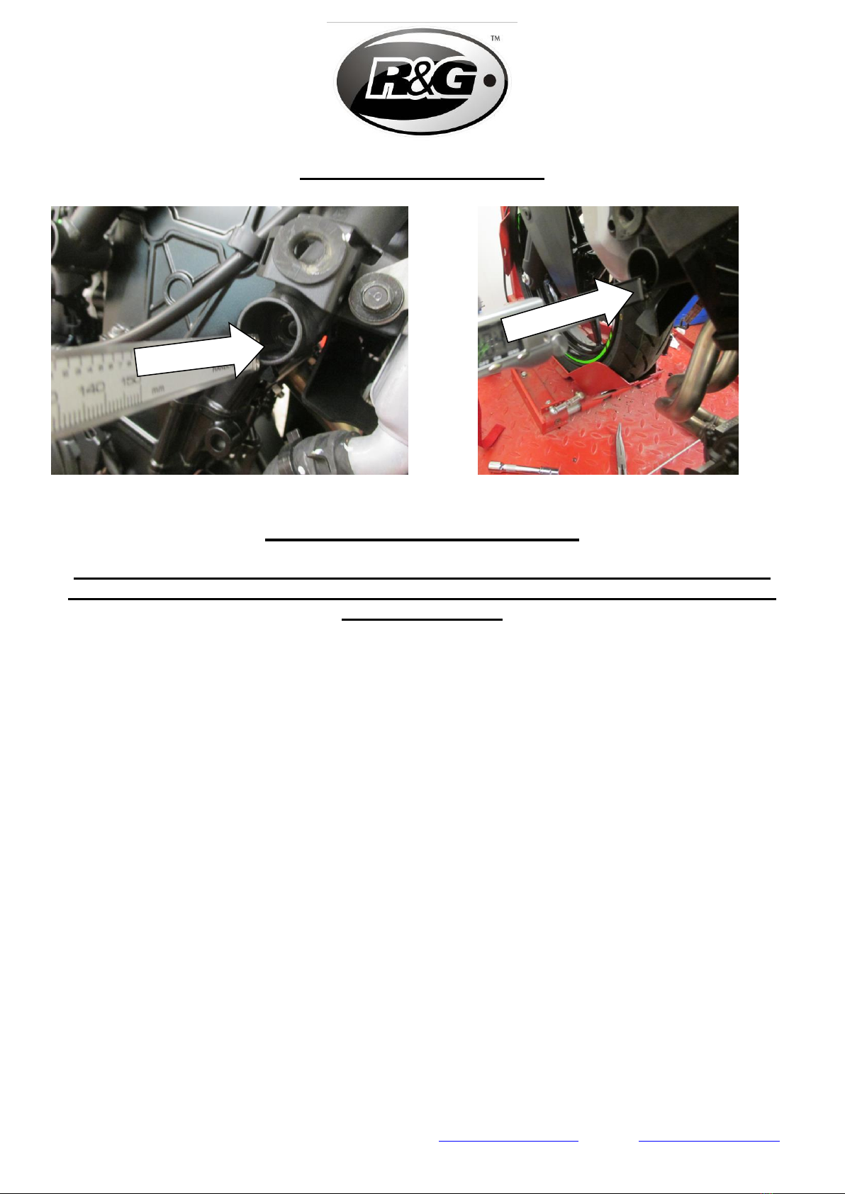
•Remove the LHS engine bolt arrowed in picture 2.
•Repeat the marking and trimming process for the LHS fairing.
•The LHS crash protector can now be fitted. Referring to LHS Assembly
Diagram 1and following the steps below:
oSlide the remaining 10mm washer (item 8) onto the M10 x 1.25 x 150mm
long hex head bolt (item 5) so the washer sits against head of bolt.
oSlide the remaining shake proof washer (item 9) over the bolt so it sits
against the washer just fitted.
oNext slide the bolt with washers through the remaining crash protector
(item 1) so the head of the bolt and washers goes into counter-bore in
the bobbin.
oLocate the longer crash protector spacer (item 4 –S1065 –90.5mm long)
over the exposed end of the bolt.
oOffer the crash protector up to the bike by locating the bolt into the LHS
frame mount so the crash protector sits into the crash protector cut out.
oTighten the bolt until you feel some compression from inside the protector
using a 17mm socket and wrench. Please note, the crash protector
must be positioned as aero-style crash protector orientation
diagram on page 2, with bigger end toward front of bike.
oTurn a little more so that you feel the compression increase slightly. Then
apply a quarter turn. Do not over tighten as damage can occur to the
bike. Do not exceed 40Nm of torque.

Page 6of 18 CP0482
R&G Racing
Unit 1, Shelley’s Lane, East Worldham, Alton, Hampshire, GU34 3AQ
•Ensure all fairings are correctly fitted with all bolts fully tightened.
•Fit crash protector caps (item 2) into both crash protectors.
•Before riding, check both sides are secure, and the crash protectors cannot
rotate.
•Check tightness of each side regularly.
ISSUE 1 04/03/2020 (DM)
CONSUMER NOTICE
The catalogue description and any exhibition of samples are only broad indications of the Products and
R&G may make design changes which do not diminish their performance or visual appeal and supplying
them in such state shall conform to the order. The Buyer acknowledges no representation or warranty
(other than as to title) has been given or will apply to the Products other than those in R&G’s order or
confirmation and the Buyer confirms it has chosen the Products as being of merchantable quality and
suitable for its particular purposes. Where R&G fits the Products or undertakes other services it shall
exercise reasonable skill and care and rectify any fault free of charge unless the workmanship has been
disturbed. The Buyer is responsible for ensuring that the warranty on the motorcycle is not affected by
the fitting of the Products. On return of any defective Products R&G shall at its option either supply a
replacement or refund the purchase money but shall not be liable if the Products have been modified or
used or maintained otherwise than in accordance with R&G’s or manufacturer’s instructions and good
engineering practice or if the defect arises from accident or neglect. Other than identified above and
subject to R&G not limiting its liability for causing death and personal injury, it shall not be liable for
indirect or consequential loss and otherwise its liability shall be limited to the amounts paid by the
Buyer for the Products or the fitting or service concerned. These terms do not affect the Buyer’s
statutory rights.
R&G RACING RETURNS POLICY (NON-FAULTY GOODS)
Returns must be pre-authorised (if not pre-authorised the return will be rejected). Goods may only be
returned direct to us if they were purchased direct from us (customer must prove if necessary).
Otherwise to be returned to original vendor. Goods must be in re-sellable condition, in the opinion of
R&G Racing. All returns are subject to a 25% restocking and handling fee (25% of the gross value exc.
P&P –at the prevailing price at time of purchase). The customer must pay any and all carriage
charges. No returns of discontinued products, unless within 14 days of purchase. This policy does not
affect your statutory rights and does not refer to faulty goods.

Page 7of 18 CP0482
R&G Racing
Unit 1, Shelley’s Lane, East Worldham, Alton, Hampshire, GU34 3AQ
Tel: +44 (0)1420 89007 Fax: +44 (0)1420 87301 www.rg-racing.com Email: info@rg-racing.com
NOTICE DE MONTAGE POUR CP0482
PROTECTIONS CRASH (KIT PERÇAGE POUR UTILISATION PISTE)
KAWASAKI NINJA 400-
LE KIT CONTIENT LES ARTICLES EXPOSES CI-DESSOUS,VERIFIER QUE TOUTES LES PIECES SOIENT PRESENTES AVANT DE PROCEDER AU
MONTAGE.
LES PARTIES PRESENTÉES PEUVENT ETRE UNIQUEMENT REPRESENTATIVES POUR LA CLARTE
DES INSTRUCTIONS UNIQUEMENT.
NE PAS PROCEDER AU MONTAGE TANT QUE VOUS N'ETES PAS SUR QUE TOUTES LES PIECES SOIENT
PRESENTES.
LIRE LES INSTRUCTIONS AVANT DE COMMENCER.
EN CAS DE DOUTE LORS DU MONTAGE DE NOS PRODUITS, CONSULTEZ UN DE NOS
REVENDEURS OU FAITES FAIRE L’INSTALLATION PAR UN TECHNICIEN QUALIFIÉ.
LA FAÇON DONT LE KIT EST EMBALLE NE CORRESPOND PAS FORCEMENT A LA FAÇON DE MONTER LES
PIECES SUR LA MOTO.
AU CAS OU DES RONDELLES EN CAOUTCHOUC SONT UTILISEES POUR MAINTENIR LES COMPOSANTS SUR
LES BOULONS,CES RONDELLES PEUVENT ETRE JETEES.
NOTICE DISPONIBLE AU TELECHARGEMENT SUR : WWW.RG-RACING.COM

Page 8of 18 CP0482
R&G Racing
Unit 1, Shelley’s Lane, East Worldham, Alton, Hampshire, GU34 3AQ
Tel: +44 (0)1420 89007 Fax: +44 (0)1420 87301 www.rg-racing.com Email: info@rg-racing.com
OUTILS REQUIS
•Dremel + Roue de coupe
•Scie trou 28mm ou similaire
•Clé à cliquet + douille 17mm
VALEURS DE SERRAGE
M4 BOULON = 8Nm
M5 BOULON = 12Nm
M6 BOULON = 15Nm
M8 BOULON = 20Nm
M10 BOULON = 40Nm
M12 BOULON = 40Nm
LÉGENDE
ARTICLE
NO.
DESCRIPTION
QTÉ
ARTICLE 1
B0472 10mm PROTECTION CRASH
2
ARTICLE 2
CAPUCHON DE BOBINE
2
ARTICLE 3
S0672 57mm ENTRETOISE DE SUPPORT CÔTÉ DROIT
1
ARTICLE 4
S1065 90.5mm ENTRETOISE DE SUPPORT CÔTÉ GAUCHE
1
ARTICLE 5
M10 x 1.25 x 150mm BOULON CÔTÉ GAUCHE
1
ARTICLE 6
M10 x 1.25 x 120mm BOULON CÔTÉ DROIT
1
ARTICLE 7
S0451 3.5mm ENTRETOISE
1
ARTICLE 8
M10 19mm RONDELLE
2
ARTICLE 9
LW0001 RONDELLE ANTI-VIBRATION
2
PROTECTION CRASH LATÉRALE

Page 10 of 18 CP0482
R&G Racing
Unit 1, Shelley’s Lane, East Worldham, Alton, Hampshire, GU34 3AQ
Tel: +44 (0)1420 89007 Fax: +44 (0)1420 87301 www.rg-racing.com Email: info@rg-racing.com
PHOTOS DU MONTAGE
Picture 1
Picture 2
NOTICE DE MONTAGE
VEUILLEZ NOTER QUE CE KIT EST CONÇU POUR ÊTRE MONTÉ EN
CONJONCTION AVEC DES CARÉNAGES DE COURSE QUI POURRAIENT
NÉCESSITER UNE MODIFICATION POUR S'ADAPTER AU KIT DE PROTECTION
CRASH.
•Retirez le carénage de la moto de façon à ce que les supports de moteur avant
soient exposés.
•Soutenez le dessous du moteur afin que le moteur ne puisse pas se déplacer
dans le cadre lorsque les boulons du moteur sont remplacés.
•Le moteur étant soutenu par le dessous, retirez le boulon moteur côté droit du
cadre, voir photo 1.
•Pour déterminer où couper le carénage pour accueillir la protection crash,
insérez un outil de marquage dans le trou du support moteur de façon à ce qu'il
soit de niveau.
•Remontez le carénage et enfoncez le carénage dans l'outil de marquage de
sorte qu'une marque soit faite à l'intérieur du panneau. Cela servira de guide
central lors de la modification du carénage.
•Utilisez une perceuse pour faire un trou pilote à l’endroit marqué, puis une
mèche ou une scie trou pour agrandir le trou afin qu'il soit suffisamment grand
pour que le boulon moteur M10 puisse passer.
•Une fois le carénage réinstallé, faites glisser la protection crash sur le boulon
plus long inclus avec ce kit et insérez-le dans le trou de carénage pour engager
avec le support de cadre côté droit, ne serrez pas, cela détaillera l’endroit où le
carénage devra être coupé pour accueillir la protection crash. Assurez-vous que

Page 11 of 18 CP0482
R&G Racing
Unit 1, Shelley’s Lane, East Worldham, Alton, Hampshire, GU34 3AQ
Tel: +44 (0)1420 89007 Fax: +44 (0)1420 87301 www.rg-racing.com Email: info@rg-racing.com
la protection crash soit complètement de niveau, utilisez un marqueur ou un
stylo pour dessiner le contour à couper.
•Utilisez un Dremel ou un outil de coupe similaire pour couper le contour du
carénage puis retirez-le.
•Assurez-vous de suivre les étapes ci-dessous avant de répéter le processus du
côté gauche de la moto. NE PAS ENLEVER LES BOULONS DE MOTEUR CÔTÉ
GAUCHE ET DROIT EN MÊME TEMPS.
•En vous référant au schéma d'assemblage côté droit 1, suivez les étapes ci-
dessous :
oGlisser la petite entretoise (article 7 - S0451 - 3,5 mm) sur le boulon à
tête hexagonale M10 x 1,25 x 120 mm de long (article 6).
oGlissez l'une des rondelles de 10 mm (article 8) sur le boulon pour que la
rondelle repose contre l'entretoise.
oGlissez une rondelle anti-vibration (article 9) sur le boulon pour qu'elle
repose contre la rondelle qui vient d'être insérée.
oFaites ensuite glisser le boulon avec les rondelles à travers l'une ou l'autre
des protections (article 1) de sorte que la tête du boulon et les rondelles
pénètrent dans le contre-alésage de la bobine.
oPlacer l'entretoise de protection anti-vibration la plus courte (article 3 -
S0672 - 57 mm de long) sur l'extrémité exposée du boulon.
oPrésentez la protection crash sur la moto en plaçant le boulon dans le
support de cadre côté droit de sorte que la protection se trouve dans la
découpe.
oSerrez le boulon jusqu'à ce que vous sentiez une compression de
l'intérieur de la protection à l'aide d'une douille et d'une clé de 17 mm.
Veuillez noter que la protection crash doit être positionnée comme sur le
schéma d'orientation de la protection à la page 2, avec l’extrémité plus
grande vers l'avant de la moto.
oTournez un peu plus pour sentir la compression augmenter légèrement.
Appliquez ensuite un quart de tour. Ne serrez pas trop car cela pourrait
endommager la moto. Ne dépassez pas 40 Nm de couple.
•Retirez le boulon moteur côté gauche fléché sur la photo 2.
•Répétez le processus de marquage et de coupe pour le carénage côté gauche.
•Le protection crash gauche peut maintenant être installée. En vous référant au
schéma d'assemblage côté gauche 1 et en suivant les étapes ci-dessous:
oFaites glisser la rondelle de 10 mm restante (article 8) sur le boulon à
tête hexagonale M10 x 1,25 x 150 mm de long (article 5) de sorte que la
rondelle repose contre la tête de boulon.
oFaites glisser la rondelle anti-vibration restante (article 9) sur le boulon
pour qu'elle repose contre la rondelle qui vient d'être montée.
oFaites ensuite glisser le boulon avec les rondelles à travers le protecteur
de collision restant (article 1) de sorte que la tête du boulon et les
rondelles pénètrent dans le contre-alésage de la bobine.

Page 12 of 18 CP0482
R&G Racing
Unit 1, Shelley’s Lane, East Worldham, Alton, Hampshire, GU34 3AQ
Tel: +44 (0)1420 89007 Fax: +44 (0)1420 87301 www.rg-racing.com Email: info@rg-racing.com
oPlacer l'entretoise la plus longue (article 4 - S1065 - 90,5 mm de long)
sur l'extrémité exposée du boulon.
oPrésentez la protection crash sur la moto en plaçant le boulon dans le
support de cadre côté gauche de sorte que la protection crash repose
dans la découpe.
oSerrez le boulon jusqu'à ce que vous sentiez une compression de
l'intérieur de la protection à l'aide d'une douille et d'une clé de 17 mm.
Veuillez noter que la protection crash doit être positionnée comme sur le
schéma d'orientation de la protection, voir page 2, avec l’extrémité plus
grande vers l'avant de la moto.
oTournez un peu plus pour sentir la compression augmenter légèrement.
Appliquez ensuite un quart de tour. Ne serrez pas trop car cela pourrait
endommager la moto. Ne dépassez pas 40 Nm de couple.
•Assurez-vous que tous les carénages soient correctement montés et que tous
les boulons soient bien serrés.
•Insérez les capuchons (article 2) dans les deux protections crash.
•Avant de rouler, vérifiez que les deux côtés soient bien fixés et que les
protections ne puissent pas tourner.
•Vérifiez régulièrement le serrage de chaque côté
ISSUE 1 04/03/2020 (DM)

Page 13 of 18 CP0482
R&G Racing
Unit 1, Shelley’s Lane, East Worldham, Alton, Hampshire, GU34 3AQ
Tel: +44 (0)1420 89007 Fax: +44 (0)1420 87301 www.rg-racing.com Email: info@rg-racing.com
MONTAGEANLEITUNG FÜR CP0482
AERO STURZPADS (BOHRERAUSRÜSTUNG FÜR RENNSPORT)
KAWASAKI NINJA 400-
ALLE KIT-TEILE SIND UNTEN ABGEBILDET UND GEKENNZEICHNET.
DIE ABGEBILDETEN TEILE DIENEN LEDIGLICH ZUR ERKLÄRUNG.
ÜBERPRÜFEN SIE ZUERST,DASS ALLE TEILE VORHANDEN SIND.
LESEN SIE DIE MONTAGEANLEITUNG KOMPLETT DURCH,BEVOR SIE ANFANGEN.
WENN SIE BEI DER MONTAGE DIESES PRODUKTES UNSICHER SIND, BITTE EINEN
UNSERER HÄNDLER KONTAKTIEREN ODER DAS KIT VON EINEM QUALIFIZIERTEN
ZWEIRAD-MECHANIKER MONTIEREN LASSEN.
DIE VERPACKUNG DER TEILE STELLT NICHT DIE REIHENFOLGE DER MONTAGE DAR.
HINWEIS FÜR KITS MIT PLASTIKUNTERLEGSCHEIBEN AN DEN SCHRAUBEN –
DIESE PLASTIK-UNTERLEGSCHEIBEN WERDEN NICHT FÜR DEN EINBAU BENÖTIGT!
EINE DIGITALE VERSION DIESER MONTAGEANLEITUNG KANN AUF
FOLGENDER SEITE HERUNTERGELADEN WERDEN:
WWW.RG-RACING.COM

Page 14 of 18 CP0482
R&G Racing
Unit 1, Shelley’s Lane, East Worldham, Alton, Hampshire, GU34 3AQ
Tel: +44 (0)1420 89007 Fax: +44 (0)1420 87301 www.rg-racing.com Email: info@rg-racing.com
SIE BENÖTIGEN FOLGENDES WERKZEUG
•Dremel-Werkzeug + Schneiderad
•28mm Lochsäge oder ähnliches
•17mm Steckschlüssel
ALLGEM. ANZUGSDREHMOMENT
M4 SCHRAUBE = 8Nm
M5 SCHRAUBE = 12Nm
M6 SCHRAUBE = 15Nm
M8 SCHRAUBE = 20Nm
M10 SCHRAUBE = 40Nm
M12 SCHRAUBE = 40Nm
LIEFERUMFANG
ARTIKEL
Nr.
BESCHREIBUNG
MENGE
ARTIKEL 1
B0472 10mm STURZPAD
2
ARTIKEL 2
STURZPAD-SCHUTZKAPPE
2
ARTIKEL 3
S0672 57mm RECHTE SEITE –DISTANZHALTER MONTAGE
1
ARTIKEL 4
S1065 90.5mm LINKE SEITE –DISTANZHALTER MONTAGE
1
ARTIKEL 5
M10 x 1,25 x 150mm SECHSKANTSCHRAUBE LINKE SEITE
1
ARTIKEL 6
M10 x 1;25 x 120mm SECHSKANTSCHRAUBE RECHTE SEITE
1
ARTIKEL 7
S0451 3,5mm DISTANZHALTER
1
ARTIKEL 8
M10 19mm UNTERLEGSCHEIBE
2
ARTIKEL 9
LW0001 ZAHNSCHEIBE
2
AERO-STYLE STURZPAD - ORIENTIERUNG
MOTORRAD HINTEN
MOTORRAD VORNE

Page 16 of 18 CP0482
R&G Racing
Unit 1, Shelley’s Lane, East Worldham, Alton, Hampshire, GU34 3AQ
Tel: +44 (0)1420 89007 Fax: +44 (0)1420 87301 www.rg-racing.com Email: info@rg-racing.com
MONTAGE - BILDER
Abbildung 1
Abbildung 2
MONTAGEANLEITUNG
WICHTIGER HINWEIS: DIESER KIT IST FÜR DEN EINBAU MIT
RENNVERKLEIDUNGEN BESTIMMT –EINE MODIFIZIERUNG IST EVENTUELL
NOTWENDIG, UM DEN STURZPAD-KIT MONTIEREN ZU KÖNNEN
•Entfernen Sie die Verkleidung vom Motorrad, so dass die vorderen
Motoraufhängungen frei sind.
•Die Unterseite des Motors stützen, so dass der Motor sich nicht innerhalb des
Rahmens bewegen kann, wenn die Motorschrauben ersetzt werden.
•Wenn der Motor ordnungsgemäß gestützt ist, entfernen Sie die Motorschraube,
die in Abbildung 1 mit einem Pfeil gekennzeichnet ist, an der rechten Seite des
Rahmens.
•Um die Verkleidung genau passend für das Sturzpad ausschneiden zu können,
zuerst eine Reißnadel horizontal in die Montageöffnung für den Motor einsetzen.
•Die Verkleidung wieder montieren und vorsichtig eindrücken, bis die Reißnadel
eine Markierung an der Innenseite hinterlässt, um somit die Position für die
Modifizierung der Verkleidung zu markieren.
•Mit einem Bohrer ein Loch an der markierten Position vorbohren. Danach mit
einem Bohreinsatz oder eine Lochsäge das Loch vergrößern, so dass genug
Platz vorhanden ist, um die M10 Motorschraube einzusetzen.
•Wenn die Verkleidung wieder montiert ist, die längere Schraube vom Kit in ein
Sturzpad einführen, dann in die Bohrung an der Verkleidung einführen und in
die Befestigung am Rahmen eindrehen, jedoch nicht festziehen. So sehen Sie
an welcher Stelle die Verkleidung ausgeschnitten werden muss, um ausreichend
Platz für das Sturzpad zu machen. Stellen Sie sicher, dass das Sturzpad

Page 17 of 18 CP0482
R&G Racing
Unit 1, Shelley’s Lane, East Worldham, Alton, Hampshire, GU34 3AQ
Tel: +44 (0)1420 89007 Fax: +44 (0)1420 87301 www.rg-racing.com Email: info@rg-racing.com
waagerecht ist, und benutzen Sie einen Markierstift oder einen Kugelschreiber,
um das Sturzpad einzuzeichnen.
•Benutzen Sie ein Dremel-Werkzeug oder ein ähnliches Schneidewerkzeug, um
den Umriss an der Verkleidung zu entgraten und entfernen.
•Achten Sie darauf, erst die nachfolgenden Schritte auszuführen, bevor Sie
anfangen, den Prozess an der linken Seite des Motorrades zu wiederholen. DIE
MOTORSCHRAUBEN FÜR DIE LINKE UND RECHTE SEITE DES MOTORS
DÜRFEN NICHT GLEICHZEITIG ENTFERNT WERDEN!
•Mit der Zeichnung Rechte Seite Zusammenbau 1als Anleitung, folgende
Schritte ausführen:
oEinen kleinen Distanzhalter (Artikel 7 –S0451 –3.5mm) an der M10 x
1,25 x 120mm Sechskantschraube (Artikel 6) montieren.
oEine 10mm (Artikel 8) Unterlegscheibe an der Schraube anbringen, so
dass die Unterlegscheibe am Distanzhalter anliegt.
oEine Zahnscheibe (Artikel 9) an der Schraube anbringen, so dass sie an
der gerade montierten Unterlegscheibe anliegt.
oDie Schraube mit den Unterlegscheiben in ein Sturzpad (Artikel 1)
einführen, sodass der Schraubenkopf in die Gegenbohrung des Sturzpads
passt.
oDen kürzeren Distanzhalter (Artikel 3 –S0672 –57mm Länge) am
hervorstehenden Ende der Schraube anbringen.
oDas Sturzpad ans Motorrad ansetzen und die Schraube in die
Rahmenbefestigung für die rechte Seite eindrehen, so dass das Sturzpad
in den vorgesehenen Ausschnitt passt.
oDie Schraube mit einem 17mm Steckschlüssel festziehen, bis Sie etwas
Druck vom Inneren des Sturzpads spüren. Bitte darauf achten, dass
das Sturzpad wie in der Zeichnung Orientierung auf Seite 2
positioniert ist –das größere Ende zum Vorderteil des Motorrades
gerichtet.
oNoch etwas drehen, bis Sie merken, dass der Druck sich leicht erhöht,
dann noch eine Vierteldrehung anwenden. Nicht überdrehen –dies kann
zu einer Beschädigung des Motorrades und der Schraube führen. 40 Nm
Anzugsmoment nicht überschreiten!
•Entfernen Sie die Motorschraube an der linken Seite, die in Abbildung 2
gekennzeichnet ist.
•Wiederholen Sie die Schritte für die Markierung und das Ausschneiden an der
linken Verkleidung.
•Das Sturzpad für die linke Seite kann nun montiert werden. Mit der Zeichnung
Linke Seite Zusammenbau 1als Anleitung, folgende Schritte ausführen:
oDie übrige 10mm (Artikel 8) Unterlegscheibe an der M10 x 1,25 x 150mm
Sechskantschraube (Artikel 5) anbringen, so dass die Unterlegscheibe am
Schraubenkopf anliegt.
oDie übrige Zahnscheibe (Artikel 9) an der Schraube anbringen, so dass sie
an der gerade montierten Unterlegscheibe anliegt.

Page 18 of 18 CP0482
R&G Racing
Unit 1, Shelley’s Lane, East Worldham, Alton, Hampshire, GU34 3AQ
Tel: +44 (0)1420 89007 Fax: +44 (0)1420 87301 www.rg-racing.com Email: info@rg-racing.com
oDie Schraube mit den Unterlegscheiben in das übrige Sturzpad (Artikel 1)
einführen, sodass der Schraubenkopf in die Gegenbohrung des Sturzpads
passt.
oDen längeren Distanzhalter (Artikel 4 –S1065 –90.5mm Länge) am
hervorstehenden Ende der Schraube anbringen.
oDas Sturzpad ans Motorrad ansetzen und die Schraube in die
Rahmenbefestigung für die linke Seite eindrehen, so dass das Sturzpad in
den vorgesehenen Ausschnitt passt.
oDie Schraube mit einem 17mm Steckschlüssel festziehen, bis Sie etwas
Druck vom Inneren des Sturzpads spüren. Bitte darauf achten, dass
das Sturzpad wie in der Zeichnung Orientierung auf Seite 2
positioniert ist –das größere Ende zum Vorderteil des Motorrades
gerichtet.
oNoch etwas drehen, bis Sie merken, dass der Druck sich leicht erhöht,
dann noch eine Vierteldrehung anwenden. Nicht überdrehen –dies kann
zu einer Beschädigung des Motorrades und der Schraube führen. 40 Nm
Anzugsmoment nicht überschreiten!
•Überprüfen Sie, dass die Motorradverkleidungen ordnungsgemäß und sicher
montiert sind und alle Schrauben festgezogen sind.
•Montieren Sie die Schutzkappen (Artikel 2) an beiden Sturzpads.
•Bevor Sie mit dem Motorrad fahren, überprüfen Sie, dass beide Seiten sicher
befestigt sind und die Sturzpads sich nicht drehen können.
•Überprüfen Sie regelmäßig, dass alles sicher befestigt ist.
AUSGABE 1 04/03/2020 (DM)
Table of contents
Languages:
Other R&G Motorcycle Accessories manuals
Popular Motorcycle Accessories manuals by other brands

Gazzini
Gazzini 10039621 Instructions for use

probiker
probiker JAKUTSK Instructions for use

SPEED & STRENGTH
SPEED & STRENGTH SS1700 user manual

hepco & becker
hepco & becker 6504522 00 01 Mounting instructions

hepco & becker
hepco & becker 6503516 01 02 quick start guide

hepco & becker
hepco & becker 7007581 00 01 quick start guide