Installation Instructions
Model G5-56 Dry sprinklers must only be installed in stan-
dard (ANSI B 16.3 class 150 and ANSI B 16.4 class 125)
pipe tees in the horizontal position, even at branch line ends.
Model G5-56 Dry sprinklers shall not be installed into elbows
or pipe couplings located on drop nipples to the sprinklers. In
all installations, including into CPVC piping, the dry sprinkler
shall be installed with protrusion into the fitting in accordance
with the installation diagrams in this Bulletin.
Installation of the Model G5-56 Dry sprinkler is not recom-
mended in copper pipe systems, as this may reduce the
life expectancy of the sprinkler. Do not install Model G5-56
Dry sprinklers with the standard (long) inlet fitting into CPVC
adapter fittings or tees that have an internal obstruction (see
Fig. 3); this will damage the sprinkler, the fitting, or both. A
short inlet (“PL”) version of the Model G5-56 Dry sprinkler is
available for use in existing installations with CPVC adapter
fittings or tees having an internal obstruction; Model G5-56
sprinklers with the short inlet fitting shall not be used on dry-
pipe sprinkler systems. The Model G5-56 Dry sprinkler and
the cover plate assembly are not intended for installation in
corrosive environments, including, but not limited to, those
with salt aerosols or chlorine.
Model G5-56 Dry sprinklers must be installed with the Ex-
posed Minimum Barrel Length required by Fig. 2 located in
a Heated Area. Do NOT install the sprinkler in ceilings which
have positive pressure in the space above.
The following steps must be followed for
installation:
1. Cut a 25
/
8-inch (67mm) diameter hole in the ceiling di-
rectly in-line with the outlet of the tee.
2. Apply pipe joint compound or Polytetrafluoroethylene
(PTFE) tape to the threads of the sprinkler’s inlet fitting.
3. A protective cap is provided to protect the drop-down
sprinkler deflector from damage which could occur dur-
ing construction before the cover plate is installed. The
cap is factory installed inside the sprinkler cup. Remove
the cap to install sprinkler, Step 4, then reinstall cap until
the cover plate is installed.
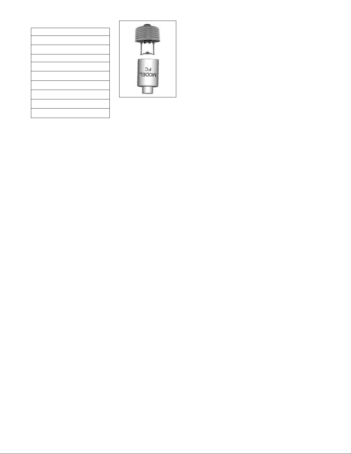
4. Install the sprinkler in the tee using the Model FC wrench.
The Model FC wrench has a socket drive which is in-
serted into the sprinkler’s cup and around the body of
the sprinkler prior to installation of the sprinkler. Do NOT
wrench any of the part of the sprinkler/cup assem-
bly. The sprinkler is then tightened into the pipe fitting
to achieve a leak free connection. The recommended
minimum to maximum installation torque is 22-30 lb-ft
(30 – 40 N-m). When inserting or removing the wrench
from the sprinkler/cup assembly, care should be taken to
prevent damage to the sprinkler. Reinstall the protective
cap following installation of the sprinkler, until the cover
plate is installed.
a. Alternatively, where access to the outer tube of the
sprinkler is available, the Model G5-56 Dry sprinkler
may be installed using a pipe wrench. The protec-
tive cap should not be removed to install the sprin-
kler with a pipe wrench. The pipe wrench shall only
be permitted to interface with the steel outer tube
portion of the sprinkler (Item #8 in Fig. 4). Do NOT
wrench any other portion of the sprinkler/cup as-
sembly. A pipe wrench can install the sprinkler into
the fitting with a large amount of torque; consider-
ation should be given to the need for future removal
of the sprinklers because the installation torque will
have to be matched or exceeded to remove the
sprinkler. The recommended minimum to maximum
installation torque is 22-30 lb-ft (30 – 40 N-m).
5. To install the cover plate, remove the protective cap and
install the cover plate by hand turning the cover in the
clockwise direction until it is tight against the ceiling.
Maintenance
The Model G5-56 Dry should be inspected and the sprinkler
system maintained in accordance with NFPA 25. Do not clean
sprinklers with soap and water, ammonia or any other cleaning
fluids. Replace any sprinkler that has been painted (other than
factory applied) or damaged in any way. Concealed sprinklers
cover plates can not be painted in the field, after installation
or have any other coating applied other than the factory finish.
A stock of spare sprinklers should be maintained to allow quick
replacement of damaged or operated sprinklers. Prior to instal-
lation, sprinkler should be maintained in the original cartons and
packaging to minimize the potential for damage to sprinklers
that would cause improper operation or non-operation.
Engineering Specification
Model G5-56 Dry Pendent Concealed Sprinkler
Dry pendent sprinklers shall be dry pendent concealed
sprinklers with a flat cover plate. Sprinklers shall be cULus
Listed as Quick Response for Light and Ordinary Hazard ap-
plications as well as FM Approved as Standard Response.
Sprinklers shall be available in lengths from 4¼ inches
(108mm) to 48 inches (1219mm) in ¼-inch (6.35mm) incre-
ments based on face of fitting to finished ceiling distance.
Sprinkler length shall be selected to provide the Exposed
Minimum Barrel Length based on the minimum design tem-
perature in the protected area and the minimum temperature
Model FC
Sprinkler Wrench
3.
Cover Plate Finishes(1)
Standard Finishes
Chrome
White Paint
Special Application Finishes(2)
Bright Brass
Finished Bronze
Black Plating
Black Paint
Off White
Satin Chrome
(1) Other finishes and colors are available on special order. Consult factory
for details. Coverplate custom paint is semi-gloss, unless specified oth-
erwise.
(2) For the perforated style coverplate, consult factory for availability on
these and other custom finishes.